EP1781913B1 - Drehpunktlagerung eines aggregates - Google Patents
Drehpunktlagerung eines aggregates Download PDFInfo
- Publication number
- EP1781913B1 EP1781913B1 EP05782545A EP05782545A EP1781913B1 EP 1781913 B1 EP1781913 B1 EP 1781913B1 EP 05782545 A EP05782545 A EP 05782545A EP 05782545 A EP05782545 A EP 05782545A EP 1781913 B1 EP1781913 B1 EP 1781913B1
- Authority
- EP
- European Patent Office
- Prior art keywords
- holder
- housing
- pivot bearing
- unit
- traction
- Prior art date
- Legal status (The legal status is an assumption and is not a legal conclusion. Google has not performed a legal analysis and makes no representation as to the accuracy of the status listed.)
- Expired - Lifetime
Links
Images


Classifications
-
- F—MECHANICAL ENGINEERING; LIGHTING; HEATING; WEAPONS; BLASTING
- F02—COMBUSTION ENGINES; HOT-GAS OR COMBUSTION-PRODUCT ENGINE PLANTS
- F02B—INTERNAL-COMBUSTION PISTON ENGINES; COMBUSTION ENGINES IN GENERAL
- F02B67/00—Engines characterised by the arrangement of auxiliary apparatus not being otherwise provided for, e.g. the apparatus having different functions; Driving auxiliary apparatus from engines, not otherwise provided for
- F02B67/04—Engines characterised by the arrangement of auxiliary apparatus not being otherwise provided for, e.g. the apparatus having different functions; Driving auxiliary apparatus from engines, not otherwise provided for of mechanically-driven auxiliary apparatus
- F02B67/06—Engines characterised by the arrangement of auxiliary apparatus not being otherwise provided for, e.g. the apparatus having different functions; Driving auxiliary apparatus from engines, not otherwise provided for of mechanically-driven auxiliary apparatus driven by means of chains, belts, or like endless members
-
- F—MECHANICAL ENGINEERING; LIGHTING; HEATING; WEAPONS; BLASTING
- F16—ENGINEERING ELEMENTS AND UNITS; GENERAL MEASURES FOR PRODUCING AND MAINTAINING EFFECTIVE FUNCTIONING OF MACHINES OR INSTALLATIONS; THERMAL INSULATION IN GENERAL
- F16H—GEARING
- F16H7/00—Gearings for conveying rotary motion by endless flexible members
- F16H7/08—Means for varying tension of belts, ropes or chains
- F16H7/10—Means for varying tension of belts, ropes or chains by adjusting the axis of a pulley
- F16H7/14—Means for varying tension of belts, ropes or chains by adjusting the axis of a pulley of a driving or driven pulley
-
- H—ELECTRICITY
- H02—GENERATION; CONVERSION OR DISTRIBUTION OF ELECTRIC POWER
- H02K—DYNAMO-ELECTRIC MACHINES
- H02K5/00—Casings; Enclosures; Supports
-
- H—ELECTRICITY
- H02—GENERATION; CONVERSION OR DISTRIBUTION OF ELECTRIC POWER
- H02K—DYNAMO-ELECTRIC MACHINES
- H02K5/00—Casings; Enclosures; Supports
- H02K5/04—Casings or enclosures characterised by the shape, form or construction thereof
- H02K5/16—Means for supporting bearings, e.g. insulating supports or means for fitting bearings in the bearing-shields
- H02K5/165—Means for supporting bearings, e.g. insulating supports or means for fitting bearings in the bearing-shields radially supporting the rotor around a fixed spindle; radially supporting the rotor directly
-
- H—ELECTRICITY
- H02—GENERATION; CONVERSION OR DISTRIBUTION OF ELECTRIC POWER
- H02K—DYNAMO-ELECTRIC MACHINES
- H02K5/00—Casings; Enclosures; Supports
- H02K5/04—Casings or enclosures characterised by the shape, form or construction thereof
- H02K5/16—Means for supporting bearings, e.g. insulating supports or means for fitting bearings in the bearing-shields
- H02K5/173—Means for supporting bearings, e.g. insulating supports or means for fitting bearings in the bearing-shields using bearings with rolling contact, e.g. ball bearings
- H02K5/1737—Means for supporting bearings, e.g. insulating supports or means for fitting bearings in the bearing-shields using bearings with rolling contact, e.g. ball bearings radially supporting the rotor around a fixed spindle; radially supporting the rotor directly
-
- H—ELECTRICITY
- H02—GENERATION; CONVERSION OR DISTRIBUTION OF ELECTRIC POWER
- H02K—DYNAMO-ELECTRIC MACHINES
- H02K5/00—Casings; Enclosures; Supports
- H02K5/26—Means for adjusting casings relative to their supports
Definitions
- the present invention relates to an engine of an internal combustion engine, which is also designed as a clamping system for a traction means of a traction mechanism drive and in particular as a starter generator.
- a housing of the unit comprises two mutually supported housing elements which form a parting plane, wherein a housing member includes a holding means which is adapted to form at least one stationary, preferably arranged on the internal combustion engine holder a pivot bearing, and one in one piece with the a fastening element connected to a housing element is formed, which is supported in the installation position via a contact surface on the holder for forming the pivot bearing.
- a traction drive is preferably provided to drive various individual units of the internal combustion engine, such as water pump, air compressor, power steering pump.
- a traction means in particular a belt
- the individual pulleys of the driven units the drive members, with the pulley of the output member, a preferably connected to the crankshaft of the internal combustion engine in connection pulley.
- the slip-free drive of all units to be driven requires a clamping system with which a sufficient, preferably slip-free bias of the traction means can be ensured.
- Such a clamping system is for example from the DE 43 00 178 C1 known, in which a tension roller in the installed state is supported by force on the traction means.
- the clamping system further comprises a stationary arranged base part, the axis of symmetry at the same time a rotation axis forms for the swivel arm, on the outside of a tension roller is rotatably arranged.
- a torsion spring is inserted between the base part and the pivot arm.
- the DE 100 57 818 A1 discloses a trained as a two-disc drive traction drive of an internal combustion engine.
- the drive takes place via a torsionally rigid with a crankshaft of the engine in connection standing output member which connects via a traction means, a belt, the other pulley, the drive member.
- a drive member to a starter generator is provided, which takes over both the function of the starter and the generator for the internal combustion engine.
- a sufficient bias of the traction means to achieve a slip-free drive is achieved with the pivotally mounted drive member, which is additionally subjected to a force by a spring means.
- Generic units are from the JP 07303342 A and the JP 07327336 known.
- the present invention is based on the object, an aggregate of an internal combustion engine, which is also designed as a clamping system for a traction means of a traction mechanism, according to the features of the preamble of claim 1, to achieve a cost-optimized pivot bearing. Furthermore, the storage should be designed so that an optimal introduction of force in the pivot bearing position.
- the invention provides that the contact surface is aligned with the parting plane of the housing elements, so that a simultaneous processing of the one Housing element in the region of the parting plane and the contact surface is made possible.
- the housing elements are supported by machined surfaces in the region of the parting plane against each other. This ensures that adjusts a large-scale support of the housing elements and thus a torsion-resistant housing.
- a further embodiment provides that only one housing element or one housing half of the unit has a fastening eye for forming the retaining means.
- the position and arrangement of the holding means is carried out so that the matching with the parting plane, jointly machined end face of the fastening eye is the contact surface with which the holding means, the fastening eye is supported on the holder.
- the inventive concepts allow a cost-optimized production of the housing, since the processing of the housing halves in the region of the parting plane requires no subsequent processing of the support surfaces or the contact surface of the holding means.
- the parting plane of the housing of the unit proceeds off-center advantageously so that it is arranged as close as possible in the direction of the pulley of the unit.
- pivot bearing according to the invention can also be combined with an eccentrically divided housing in which the housing element associated with the traction means is made wider in comparison to the associated further housing element.
- a preferred embodiment of the invention provides that the holder, which is directly or indirectly in communication with the internal combustion engine one includes rotatable sleeve, which is rotationally fixed in the installed state of the holding means of the pivotable unit.
- a screw with which the components of the pivot bearing, the bush of the holder and the holder are clamped serves as fastening means.
- a further embodiment of the invention relates to the design of the holder, which is designed according to the invention as a U-shaped carrier or as a fork. These components form two axially staggered shots, between which the or the fastening eyes are used.
- a shaft or a fastening screw connects the receptacles, at the same time guides the holding means and consequently the unit is positioned therewith.
- a receptacle is designed as a fixed bearing and the further receptacle as a floating bearing.
- a fastener is preferably a self-tapping or self-tapping screw alone, d. H. without nut allows an effective, permanent connection and fuse.
- the clamping system according to the invention represented by the pivotable about the pivot bearing unit to assign a separate bracket or bracket, which is preferably secured by means of a screw detachable to the internal combustion engine.
- the console forms a holder which forms the pivot bearing with holding means of the unit.
- An optimal low-friction mounting of the unit can advantageously take place via a sliding bearing, with which the socket is inserted into the holder and torsionally rigidly connected to the unit.
- the invention also includes a reverse arrangement, in which the bush is rotatably associated with the holding means, for example the fastening eyes of the generator, via a slide bearing and which is fixed in position relative to the holder on the other hand.
- the pivot bearing according to the invention can also be coupled with a damping device, so as to eliminate adverse resonances of the traction mechanism drive or damp due to the rotational nonuniformity of the internal combustion engine in the traction drive introduced vibrations.
- a damping device it is advisable to form the preloaded pivot bearing, in which, for example, between the relatively rotatable components of the pivot bearing a friction disc is arranged.
- a slip-free drive of the traction mechanism drive requires a sufficiently biased traction means.
- the pivotable unit which simultaneously assumes the function of the clamping system, provided with a pivot bearing whose position makes it possible to use the weight of the pivotable unit to influence the bias of the traction means.
- Supporting a force means can be additionally provided, with which the unit, the starter generator, is subjected to a force in a direction of rotation, which biases the traction means.
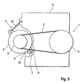
- the traction mechanism drive 1 is designed as a two-disc drive, in which a traction means 2, a driven member 3, a connected to a crankshaft of an internal combustion engine 4 belt pulley and another pulley of a drive member 5 connects.
- a pivotally mounted unit 6 in particular a starter generator is provided, which takes over the function of a generator for the internal combustion engine 4 depending on the operating mode in the starting phase, the function of the starter and the internal combustion engine 4.
- the unit 6 is pivotable about an axis of rotation 7 of a pivot bearing 8.
- the pivot bearing 8 comprises an integrally with the internal combustion engine 4 related holder 9 and associated holding means 10 of the unit 6.
- a pivoting of the unit 6 in the counterclockwise direction increases the bias of the traction means 2.
- the position of the pivot bearing 8 favors the bias of the traction means 2, there this utilizes the weight of the aggregate 6 to exert a counterclockwise force component.
- the unit 6, which takes over the function of a clamping system 11, is provided with a force means 12, in particular a spring inserted between the internal combustion engine 4 and the unit 6, with which the bias of the traction means 2 can be increased.
- the FIG. 1 shows a first pivot bearing 17a, which as a holding means 20a integrally with a housing 13 of the unit 6 connected fastening eyes 14, 15 and includes a holder 19a.
- the housing 13 of the unit 6 is formed from the two housing elements 16a, 16b, which are supported via a parting plane 18a.
- the parting plane 18a continues over the region of the fastening eyes 14, 15, so that by means of a machining of the respective housing element 16a, 16b including the associated fastening eyes 14 and 15 at the same time a support surface 21 is machined, on which the fastening eyes 14, 15 in support the installation position.
- the attachment eye 14 is further supported with a face remote from the support surface 21 end face directly on an end face of the holder 19 a, which together form a contact surface 22.
- the directly or indirectly connected to the engine 4 holder 19a is provided with a through hole 23 into which a socket 24 is inserted.
- a socket 24 is inserted into which a socket 24 is inserted.
- the sleeve 24 relative to the holder 19a is inserted in an annular gap which adjoins between the through hole 23 and a lateral surface of the sleeve 24, a sliding bearing 25.
- the bushing 24 by means of a fastening means, a screw 26 is frictionally supported on the mounting eye 14 and thus the holding means 20a.
- a desired rotation of the bushing 24 in the operating state with respect to the holder 19 a since the sleeve 24 rotatably connected to the holding means 20 a and thus the unit 6 is connected.
- the screw 26 is initially guided in a receiving bore 27 of the fastening eye 14 and further screwed into a threaded bore 28 of the fastening eye 15.
- a sealing ring 29 is provided, which seals a self-adjusting annular gap 30 between the holder 19 a and the sleeve 24.
- the end face of the sealing ring 28 is covered by a disc 31 which is inserted between a screw head 32 and the bush 24.
- the design of the pivot bearing 17a allows a shift in the direction of the traction means 2, whereby the force introduced by the traction means 2 in the unit 6 in the direction of arrow force direction triggers a reduced tilting moment in the pivot bearing 17a, which advantageously affects the load of the sliding bearing 25, whereby a increased life is feasible.
- two further embodiments shown are those with the first embodiment ( FIG. 1 ) Matching components provided with the same reference numerals, so that reference can be made to avoid repetition of the description of the first embodiment.
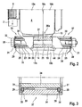
- FIG. 2 shows the pivot bearing 17b, which includes a U-shaped holder 19b, for example, a separate console, which is on the one hand releasably attached to the internal combustion engine 4 and two axially spaced receptacles 33, 34 includes. Between the receptacles 33, 34, the holding means 20a, consisting of the fastening eyes 14, 15 are used. The receptacles 33, 34 in conjunction with the sockets 24 inserted therein, according to the first embodiment allow a backlash-free arrangement. In the installed state, the sockets 24 are pressed by means of the screw 35 via the contact surfaces 22, 44 to the holding means 20a, the fastening eyes 14, 15.
- the structure of the floating bearing 37 illustrates the FIG. 3 ,
- the recording shown in an enlarged scale 34 shows the floating bearing 37 in the installed state, in which the design of the sleeve 24 ensures a projection 38 against a frontal contour 39 of the receptacle 34.
- the supernatant 38 which acts as an installation, effectively prevents the disc 31 from abutting the contour 39 of the receptacle 24, as a result of which the unit 6 can pivot freely in the operating state.
- FIG. 4 shows an embodiment with the pivot bearing 17c, which the holder 19a according to the embodiment of FIG. 1 includes as well as that Holding means 20b.
- the unit 6 is according to FIG. 4 provided with a parting plane 18 b, which is arranged offset in the direction of the traction means 2.
- This structure further advantageously reduces a transverse force, which is introduced by the traction means 2 in the arrow direction in the pivot bearing 17c, due to a reduced distance between the traction means 2 and the pivot bearing 17c,
- the retaining means 20b comprises only one fastening eye 40 integrally connected to the housing element 16b, the contact surface 42 of which extends in alignment with the parting plane 18a.
- the parting plane 18ab as well as the contact surface 42 can be processed inexpensively in one operation. Due to the relatively large width of the fastening eye 40, it makes sense to use as a fastener a self-tapping screw 41 which is self-tapping screwed into a partially prepared threaded hole 43 of the fastening eye 40, to achieve a fixed position support of the sleeve 24 via the contact surface 42 on the Fixing eye 40.
Landscapes
- Engineering & Computer Science (AREA)
- General Engineering & Computer Science (AREA)
- Power Engineering (AREA)
- Mechanical Engineering (AREA)
- Chemical & Material Sciences (AREA)
- Combustion & Propulsion (AREA)
- Connection Of Motors, Electrical Generators, Mechanical Devices, And The Like (AREA)
- Shafts, Cranks, Connecting Bars, And Related Bearings (AREA)
- Mounting Of Bearings Or Others (AREA)
- Devices For Conveying Motion By Means Of Endless Flexible Members (AREA)
Abstract
Description
- Die vorliegende Erfindung betrifft ein Aggregat einer Brennkraftmaschine, das zugleich als Spannsystem für ein Zugmittel eines Zugmitteltriebs und insbesondere als Startergenerator ausgebildet ist. Ein Gehäuse des Aggregats umfasst zwei gegeneinander abgestützte Gehäuseelemente, die eine Trennebene bilden, wobei ein Gehäuseelement ein Haltemittel einschließt, das dazu ausgebildet ist, mit zumindest einem ortsfest, vorzugsweise an der Brennkraftmaschine angeordneten Halter ein Drehlager zu bilden, und das aus einem einstückig mit dem einen Gehäuseelement verbundenen Befestigungsauge gebildet wird, das in der Einbaulage über eine Kontaktfläche an dem Halter zur Bildung des Drehlagers abgestützt ist.
- Zum Antrieb verschiedener Einzelaggregate der Brennkraftmaschine, wie Wasserpumpe, Klimakompressor, Lenkhilfspumpe, ist vorzugsweise ein Zugmitteltrieb vorgesehen. Dazu verbindet ein Zugmittel, insbesondere ein Riemen, die einzelnen Riemenscheiben der anzutreibenden Aggregate, den Antriebsorganen, mit der Riemenscheibe des Abtriebsorgans, eine vorzugsweise mit der Kurbelwelle der Brennkraftmaschine in Verbindung stehende Riemenscheibe. Der schlupffreie Antrieb aller anzutreibenden Aggregate erfordert ein Spannsystem, mit dem eine ausreichende, vorzugsweise schlupffreie Vorspannung des Zugmittels sichergestellt werden kann.
- Ein derartiges Spannsystem ist beispielsweise aus der
DE 43 00 178 C1 bekannt, bei dem eine Spannrolle im eingebauten Zustand an dem Zugmittel kraftbeaufschlagt abgestützt ist. Das Spannsystem umfasst weiterhin ein ortsfest angeordnetes Basisteil, dessen Symmetrieachse gleichzeitig eine Drehachse für den Schwenkarm bildet, an dem außenseitig eine Spannrolle drehbar angeordnet ist. Zur Erzielung einer kraftschlüssigen Abstützung der Spannrolle an dem Zugmittel ist zwischen dem Basisteil und dem Schwenkarm eine Torsionsfeder eingesetzt. - Die
DE 100 57 818 A1 offenbart einen als Zweischeibentrieb ausgebildeten Zugmitteltrieb einer Brennkraftmaschine. Der Antrieb erfolgt dabei über ein drehstarr mit einer Kurbelwelle der Brennkraftmaschine in Verbindung stehendes Abtriebsorgan, das über ein Zugmittel, einen Riemen, die weitere Riemenscheibe, das Antriebsorgan verbindet. Als Antriebsorgan ist dazu ein StarterGenerator vorgesehen, der für die Brennkraftmaschine sowohl die Funktion des Starters als auch des Generators übernimmt. Eine ausreichende Vorspannung des Zugmittels, zur Erzielung eines schlupffreien Antriebs wird mit dem schwenkbar angeordneten Antriebsorgan erreicht, das zusätzlich von einem Federmittel kraftbeaufschlagt ist. - Gattungsgemäße Aggregate sind aus der
JP 07303342 A JP 07327336 - Der vorliegenden Erfindung liegt die Aufgabe zugrunde, ein Aggregat einer Brennkraftmaschine, das zugleich als ein Spannsystem für ein Zugmittel eines Zugmitteltriebs ausgelegt ist, nach den Merkmalen des Oberbegriffs von Anspruch 1 weiterzubilden, zur Erzielung einer kostenoptimierten Drehpunktlagerung. Weiterhin soll die Lagerung so gestaltet werden, dass sich eine optimale Krafteinleitung in die Drehpunktlagerung einstellt.
- Erfindungsgemäß wird diese Aufgabe durch die Merkmale des Anspruchs 1 gelöst.
- Die Erfindung sieht vor, dass die Kontaktfläche fluchtend mit der Trennebene der Gehäuseelemente verläuft, so dass eine gleichzeitige Bearbeitung des einen Gehäuseelements im Bereich der Trennebene und der Kontaktfläche ermöglicht ist. Die Gehäuseelemente sind dabei über bearbeitete Flächen im Bereich der Trennebene gegeneinander abgestützt. Damit ist sichergestellt, dass sich eine großflächige Abstützung der Gehäuseelemente und damit ein verwindungssteifes Gehäuse einstellt.
- Eine weitere Ausgestaltung sieht vor, dass zur Bildung des Haltemittels nur ein Gehäuseelement bzw. eine Gehäusehälfte des Aggregats ein Befestigungsauge aufweist. Die Lage und Anordnung des Haltemittels erfolgt dabei so, dass die mit der Trennebene übereinstimmende, gemeinsam bearbeitete Stirnfläche des Befestigungsauges die Kontaktfläche darstellt, mit der das Haltemittel, das Befestigungsauge an dem Halter abgestützt ist.
- Die erfindungsgemäßen Konzepte ermöglichen eine kostenoptimierte Fertigung des Gehäuses, da die Bearbeitung der Gehäusehälften im Bereich der Trennebene keine nachträgliche Bearbeitung der Abstützflächen oder der Kontaktfläche der Haltemittel erfordert.
- Die Trennebene von dem Gehäuse des Aggregats verläuft außermittig vorteilhaft so, dass diese möglichst nahe in Richtung der Riemenscheibe des Aggregats angeordnet ist. Durch die Zuordnung des Haltemittels an dem breiteren, von der Riemenscheibe abgewandten Gehäuseelement kann ein sich zwischen der Krafteinleitung des Zugmittels und dem Drehlager einstellender Hebelarm vorteilhaft verringert werden. Der verkürzte Hebelarm verringert wirksam das Kippmoment und die damit verbundene Kantenlast des Gleitlagers.
- Alternativ dazu ist das erfindungsgemäße Drehlager ebenfalls mit einem außermittig geteilten Gehäuse kombinierbar, bei dem das dem Zugmittel zugeordnete Gehäuseelement breiter ausgeführt ist im Vergleich zu dem zugehörigen weiteren Gehäuseelement.
- Eine bevorzugte Ausgestaltung der Erfindung sieht vor, dass der Halter, der mit der Brennkraftmaschine mittelbar oder unmittelbar in Verbindung steht eine drehbare Buchse einschließt, die im Einbauzustand an dem Haltemittel des schwenkbaren Aggregates drehfixiert ist. Als Befestigungsmittel dient dabei insbesondere eine Schraube, mit der die Bauteile des Drehlagers, die Buchse des Halters und der Halter verspannt sind.
- Eine weitere Ausgestaltung der Erfindung bezieht sich auf die Gestaltung des Halters, der erfindungsgemäß als U-förmiger Träger oder als Gabel gestaltet ist. Diese Bauteile bilden zwei axial zueinander versetzte Aufnahmen, zwischen denen das bzw. die Befestigungsaugen eingesetzt sind. Eine Welle bzw. eine Befestigungsschraube verbindet die Aufnahmen, führt gleichzeitig das Haltemittel und folglich ist damit das Aggregat positioniert.
- Zur Erzielung einer ungehinderten Funktion des Drehlagers, bei dem das Haltemittel mit einem zwei Aufnahmen aufweisenden Halter zusammenwirkt, wird erreicht, in dem eine Aufnahme als Festlager und die weitere Aufnahme als Loslager ausgebildet ist.
- Als Befestigungsmittel eignet sich bevorzugt eine selbstfurchende bzw. selbstschneidende Schraube, die allein, d. h. ohne Schraubenmutter eine wirksame, dauerfeste Verbindung und Sicherung ermöglicht.
- Vorteilhaft bietet es sich außerdem an, dem erfindungsgemäßen Spannsystem, dargestellt durch das über das Drehlager schwenkbare Aggregat, eine separate Konsole bzw. Bracket zuzuordnen, die bevorzugt mittels einer Verschraubung lösbar an der Brennkraftmaschine befestigt ist. Die Konsole bildet dabei einen Halter, der mit Haltemitteln des Aggregats das Drehlager bildet.
- Eine optimale reibungsarme Lagerung des Aggregats kann vorteilhaft über ein Gleitlager erfolgen, mit dem die Buchse in dem Halter eingesetzt und drehstarr mit dem Aggregat verbunden ist. Alternativ schließt die Erfindung ebenfalls eine umgekehrte Anordnung ein, bei der die Buchse über ein Gleitlager drehbar dem Haltemittel, beispielsweise den Befestigungsaugen des Generators zugeordnet ist und die andererseits gegenüber dem Halter lagefixiert ist.
- Das erfindungsgemäße Drehlager kann außerdem mit einer Dämpfungseinrichtung gekoppelt werden, um so nachteilige Resonanzen des Zugmitteltriebs zu eliminieren oder aufgrund der Drehungleichförmigkeit der Brennkraftmaschine in den Zugmitteltrieb eingeleitete Schwingungen zu dämpfen. Als Dämpfungseinrichtung bietet es sich an, das Drehlager vorgespannt auszubilden, bei dem beispielsweise zwischen den sich relativ verdrehbaren Bauteilen des Drehlagers eine Reibscheibe angeordnet ist.
- Ein schlupffreier Antrieb des Zugmitteltriebs erfordert ein ausreichend vorgespanntes Zugmittel. Bevorzugt ist das schwenkbare Aggregat, das gleichzeitig die Funktion des Spannsystems übernimmt, mit einem Drehlager versehen, dessen Lage es ermöglicht, das Eigengewicht des schwenkbaren Aggregats zu nutzen, um die Vorspannung des Zugmittels zu beeinflussen. Unterstützend kann ein Kraftmittel zusätzlich vorgesehen werden, mit dem das Aggregat, der Startergenerator, in eine Drehrichtung kraftbeaufschlagt wird, die das Zugmittel vorspannt.
- Nachfolgend wird die Erfindung anhand von dre (
Figuren 3 ,4 ,5 ) in insgesamt fünf Figuren abgebildeten Ausführungsbeispielen näher erläutert. Es zeigen: - Figur 1
- den Aufbau eines Drehlagers eines Spannsystems;
- Figur 2
- ein weiteres Drehlager für ein Spannsystem;
- Figur 3
- in einer vergrößerten Darstellung ein Detail des Drehlagers gemäß
Figur 2 ; - Figur 4
- einen Teilbereich eines schwenkbar als Spannsystem ausgeführten Aggregats, bei dem das Haltemittel mit nur einem Gehäuseelement des Aggregats verbunden ist;
- Figur 5
- in einer prinzipiellen Darstellung einen Zugmitteltrieb, der als Spann- system ein schwenkbares Aggregat einschließt.
- Zunächst wird anhand der
Figur 5 ein bekanntes Spannsystem für einen Zugmitteltrieb erläutert, bestehend aus einem schwenkbar angeordneten Aggregat. Der Zugmitteltrieb 1 gemäßFigur 5 ist als ein Zweischeibentrieb ausgeführt, bei dem ein Zugmittel 2 ein Abtriebsorgan 3, ein mit einer Kurbelwelle einer Brennkraftmaschine 4 verbundenes Riemenrad sowie ein weiteres Riemenrad eines Antriebsorgans 5 verbindet. Als Antriebsorgan 5 ist ein schwenkbar angeordnetes Aggregat 6, insbesondere ein Startergenerator vorgesehen, welcher für die Brennkraftmaschine 4 abhängig vom Betriebsmodus in der Startphase die Funktion des Starters und bei laufender Brennkraftmaschine 4 die Funktion eines Generators übernimmt. - Zur Erzielung einer ausreichenden Vorspannung des Zugmittels 2 ist das Aggregat 6 um eine Drehachse 7 eines Drehlagers 8 schwenkbar. Das Drehlager 8 umfasst einen einstückig mit der Brennkraftmaschine 4 in Verbindung stehenden Halter 9 sowie zugehörige Haltemittel 10 des Aggregates 6. Ein Verschwenken des Aggregates 6 im Gegenuhrzeigersinn erhöht die Vorspannung des Zugmittels 2. Die Lage des Drehlagers 8 begünstigt die Vorspannung des Zugmittels 2, da diese das Gewicht des Aggregates 6 nutzend eine im Gegenuhrzeigersinn ausübende Kraftkomponente ausübt. Das Aggregat 6, welches die Funktion eines Spannsystems 11 übernimmt, ist versehen mit einem Kraftmittel 12, insbesondere eine zwischen der Brennkraftmaschine 4 und dem Aggregat 6 eingesetzten Feder, mit der die Vorspannung des Zugmittels 2 erhöht werden kann.
- Die
Figur 1 zeigt ein erstes Drehlager 17a, welches als Haltemittel 20a einstückig mit einem Gehäuse 13 des Aggregats 6 verbundene Befestigungsaugen 14, 15 umfasst sowie einen Halter 19a. Das Gehäuse 13 des Aggregates 6 wird aus den zwei Gehäuseelementen 16a, 16b, gebildet, die über eine Trennebene 18a abgestützt sind. Die Trennebene 18a setzt sich über den Bereich der Befestigungsaugen 14, 15 fort, so dass mittels einer Bearbeitung des jeweiligen Gehäuseelementes 16a, 16b einschließlich der zugehörigen Befestigungsaugen 14 bzw. 15 gleichzeitig eine Abstützfläche 21 bearbeitet ist, über die sich die Befestigungsaugen 14, 15 in der Einbaulage abstützen. - Das Befestigungsauge 14 ist weiterhin mit einer von der Abstützfläche 21 abgewandten Stirnfläche unmittelbar an einer Stirnfläche des Halters 19a abgestützt, die gemeinsam eine Kontaktfläche 22 bilden. Der direkt oder indirekt mit der Brennkraftmaschine 4 verbundene Halter 19a ist mit einer Durchgangsbohrung 23 versehen, in die eine Buchse 24 eingesetzt ist. Zur Erzielung einer Relativbewegung bzw. Relatiwerdrehung der Buchse 24 gegenüber dem Halter 19a ist in einem Ringspalt, der sich zwischen der Durchgangsbohrung 23 und einer Mantelfläche der Buchse 24 einstellt ein Gleitlager 25 eingesetzt. Im Einbauzustand ist die Buchse 24 mittels eines Befestigungsmittels, einer Schraube 26 kraftschlüssig an dem Befestigungsauge 14 und damit dem Haltemittel 20a abgestützt.
- Durch diese Maßnahme stellt sich im Betriebszustand eine gewollte Verdrehung der Buchse 24 gegenüber dem Halter 19a ein, da die Buchse 24 drehfest mit dem Haltemittel 20a und damit dem Aggregat 6 verbunden ist. Die Schraube 26 ist dabei zunächst in einer Aufnahmebohrung 27 des Befestigungsauges 14 geführt und weiterhin in einer Gewindebohrung 28 des Befestigungsauges 15 eingeschraubt. Zur Abdichtung des Gleitlagers 25 ist ein Dichtring 29 vorgesehen, welcher einen sich einstellenden Ringspalt 30 zwischen dem Halter 19a und der Buchse 24 abdichtet. Stirnseitig ist der Dichtring 28 von einer Scheibe 31 abgedeckt, die zwischen einem Schraubenkopf 32 und der Buchse 24 eingesetzt ist. Vorteilhaft ermöglicht die Gestaltung des Drehlagers 17a eine Verschiebung in Richtung des Zugmittels 2, wodurch die vom Zugmittel 2 in das Aggregat 6 in Pfeilrichtung eingebrachte Kraftrichtung ein verringertes Kippmoment in dem Drehlager 17a auslöst, was sich vorteilhaft auf die Belastung des Gleitlagers 25 auswirkt, wodurch eine erhöhte Lebensdauer realisierbar ist. Bei den in den
Figuren 2 und4 gezeigten zwei weiteren Ausführungsbeispielen sind die mit dem ersten Ausführungsbeispiel (Figur 1 ) übereinstimmenden Bauteile mit gleichen Bezugsziffern versehen, so dass zur Vermeidung von Wiederholungen auf die Beschreibung des ersten Ausführungsbeispiels Bezug genommen werden kann. - Die
Figur 2 zeigt das Drehlager 17b, die einen U-förmig gestalteten Halter 19b umfasst, beispielsweise eine separate Konsole, die einerseits lösbar an der Brennkraftmaschine 4 befestigt ist und zwei axial beabstandete Aufnahmen 33, 34 umfasst. Zwischen den Aufnahmen 33, 34 ist das Haltemittel 20a, bestehend aus den Befestigungsaugen 14, 15 eingesetzt. Die Aufnahmen 33, 34 in Verbindung mit den darin eingesetzten Buchsen 24, gemäß dem ersten Ausführungsbeispiel ermöglichen eine spielfreie Anordnung. Im Einbauzustand werden die Buchsen 24 mittels der Schraube 35 über die Kontaktflächen 22, 44 an das Haltemittel 20a, die Befestigungsaugen 14, 15 gepresst. Dieser kraftschlüssige Verband gewährleistet bei einer Schwenkbewegung des Aggregats 6 eine Relativbewegung der Buchsen 24 gegenüber der jeweiligen Aufnahme 33, 34, wobei die Aufnahmen vergleichbar dem Ausführungsbeispiel gemäßFigur 1 Gleitlager 25 umfassen. Zur Erzielung einer reibungsarmen Wirkungsweise des Drehlagers 17b schließt dieses eine als Festlager 36 ausgebildete Aufnahme 33 sowie eine als Loslager 37 ausgeführte Aufnahme 34 ein. - Den Aufbau des Loslagers 37 verdeutlicht die
Figur 3 . Die in einem vergrößerten Maßstab abgebildete Aufnahme 34 zeigt das Loslager 37 im eingebauten Zustand, bei dem die Gestaltung der Buchse 24 einen Überstand 38 gegenüber einer stirnseitigen Kontur 39 der Aufnahme 34 sicherstellt. Der ein Einbauspiel darstellende Überstand 38 verhindert wirksam eine Anlage der Scheibe 31 an der Kontur 39 der Aufnahme 24, wodurch das Aggregat 6 im Betriebszustand ungehindert verschwenken kann. - Die
Figur 4 zeigt ein Ausführungsbeispiel mit dem Drehlager 17c, welches den Halter 19a gemäß dem Ausführungsbeispiel ausFigur 1 umfasst sowie das Haltemittel 20b. Abweichend zu den zuvor beschriebenen Ausführungsbeispielen ist das Aggregat 6 gemäßFigur 4 mit einer Trennebene 18b versehen, die in Richtung des Zugmittels 2 versetzt angeordnet ist. Dieser Aufbau verringert weiterhin in vorteilhafter Weise eine Querkraft, die von dem Zugmittel 2 in Pfeilrichtung in das Drehlager 17c eingeleitet wird, aufgrund eines reduzierten Abstandes zwischen dem Zugmittel 2 und dem Drehlager 17c, - Das Haltemittel 20b umfasst lediglich ein einstückig mit dem Gehäuseelement 16b verbundenes Befestigungsauge 40, dessen Kontaktfläche 42 fluchtend mit der Trennebene 18a verläuft. Vorteilhaft kann damit die Trennebene 18ab wie auch die Kontaktfläche 42 kostengünstig in einem Arbeitsvorgang bearbeitet werden. Aufgrund der relativ großen Breite des Befestigungsauges 40 bietet es sich an, als Befestigungsmittel eine selbstfurchende Schraube 41 zu verwenden, die selbstschneidend in eine teilweise vorbereitete Gewindebohrung 43 des Befestigungsauges 40 eingeschraubt ist, zur Erzielung einer lagefixierten Abstützung der Buchse 24 über die Kontaktfläche 42 an dem Befestigungsauge 40.
-
- 1
- Zugmitteltrieb
- 2
- Zugmittel
- 3
- Abtriebsorgan
- 4
- Brennkraftmaschine
- 5
- Antriebsorgan
- 6
- Aggregat
- 7
- Drehachse
- 8
- Drehlager
- 9
- Halter
- 10
- Haltemittel
- 11
- Spannsystem
- 12
- Kraftmittel
- 13
- Gehäuse
- 14
- Befestigungsauge
- 15
- Befestigungsauge
- 16a
- Gehäuseelement
- 16b
- Gehäuseelement
- 17a
- Drehlager
- 17b
- Drehlager
- 17c
- Drehlager
- 18a
- Trennebene
- 18 b
- Trennebene
- 19a
- Halter
- 19b
- Halter
- 20a
- Haltemittel
- 20b
- Haltemittel
- 21
- Abstützfläche
- 22
- Kontaktfläche
- 23
- Durchgangsbohrung
- 24
- Buchse
- 25
- Gleitlager
- 26
- Schraube
- 27
- Aufnahmebohrung
- 28
- Gewindebohrung
- 29
- Dichtring
- 30
- Ringspalt
- 31
- Scheibe
- 32
- Schraubenkopf
- 33
- Aufnahme
- 34
- Aufnahme
- 35
- Schraube
- 36
- Festlager
- 37
- Festlager
- 38
- Überstand
- 39
- Kontur
- 40
- Befestigungsauge
- 41
- Schraube
- 42
- Kontaktfläche
- 43
- Gewindebohrung
- 44
- Kontaktfläche
Claims (1)
- Aggregat einer Brennkraftmaschine (4), das zugleich als Spannsystem für ein Zugmittel (2) eines Zugmitteltriebs (1) und insbesondere als Startergenerator ausgebildet ist, wobei ein Gehäuse (13) des Aggregats (6) zwei gegeneinander abgestützte Gehäuseelemente (16a, 16b) umfasst, die eine Trennebene (18b) bilden, wobei ein Gehäuseelement (16b) ein Haltemittel (20b) einschließt, das dazu ausgebildet ist, mit zumindest einem ortsfest, vorzugsweise an der Brennkraftmaschine (4) angeordneten Halter (9; 19a) ein Drehlager (8; 17c) zu bilden, und das aus einem einstückig mit dem einen Gehäuseelement (16b) verbundenen Befestigungsauge (40) gebildet wird, das in der Einbaulage über eine Kontaktfläche (42) an dem Halter (19a) zur Bildung des Drehlagers (8, 17c) abgestützt ist, dadurch gekennzeichnet, dass die Kontaktfläche (42) fluchtend mit der Trennebene (18b) der Gehäuseelemente (16a, 16b) verläuft, so dass eine gleichzeitige Bearbeitung des einen Gehäuseelements (16b) im Bereich der Trennebene (18b) und der Kontaktfläche (42) ermöglicht ist.
Applications Claiming Priority (2)
| Application Number | Priority Date | Filing Date | Title |
|---|---|---|---|
| DE102004041044A DE102004041044A1 (de) | 2004-08-25 | 2004-08-25 | Drehpunktlagerung eines Aggregates |
| PCT/EP2005/008228 WO2006021287A1 (de) | 2004-08-25 | 2005-07-29 | Drehpunktlagerung eines aggregates |
Publications (2)
| Publication Number | Publication Date |
|---|---|
| EP1781913A1 EP1781913A1 (de) | 2007-05-09 |
| EP1781913B1 true EP1781913B1 (de) | 2011-09-14 |
Family
ID=35345126
Family Applications (1)
| Application Number | Title | Priority Date | Filing Date |
|---|---|---|---|
| EP05782545A Expired - Lifetime EP1781913B1 (de) | 2004-08-25 | 2005-07-29 | Drehpunktlagerung eines aggregates |
Country Status (6)
| Country | Link |
|---|---|
| US (1) | US20070259745A1 (de) |
| EP (1) | EP1781913B1 (de) |
| KR (1) | KR20070047791A (de) |
| CN (1) | CN101006259A (de) |
| DE (1) | DE102004041044A1 (de) |
| WO (1) | WO2006021287A1 (de) |
Families Citing this family (9)
| Publication number | Priority date | Publication date | Assignee | Title |
|---|---|---|---|---|
| JP4260066B2 (ja) * | 2004-05-31 | 2009-04-30 | 株式会社リコー | ベルト搬送装置及び画像形成装置 |
| US20080081718A1 (en) * | 2006-09-28 | 2008-04-03 | Collier-Hallman Steven J | Load dependent belt tensioner |
| SE541951C2 (sv) | 2013-02-04 | 2020-01-14 | Scania Cv Ab | Länkarrangemang |
| JP6291683B2 (ja) * | 2014-03-18 | 2018-03-14 | サンデンホールディングス株式会社 | エンジン補機の取付装置 |
| CN105626261B (zh) * | 2016-02-18 | 2018-06-29 | 广西玉柴机器股份有限公司 | 一种多功能前端支撑架 |
| JP6414113B2 (ja) * | 2016-03-24 | 2018-10-31 | 株式会社デンソー | 燃料供給装置 |
| FR3058772B1 (fr) * | 2016-11-16 | 2020-05-08 | Renault S.A.S. | Moteur equipe d'une liaison elastique pour tendre la courroie de transmission |
| DE102016226208A1 (de) * | 2016-12-23 | 2018-06-28 | Robert Bosch Gmbh | Verfahren zur Montage einer Maschine an einem Halteblock |
| JP7236940B2 (ja) * | 2019-06-04 | 2023-03-10 | ダイハツ工業株式会社 | 内燃機関 |
Family Cites Families (13)
| Publication number | Priority date | Publication date | Assignee | Title |
|---|---|---|---|---|
| US2856786A (en) * | 1955-09-21 | 1958-10-21 | Us Slicing Machine Co Inc | Belt tensioner for slicing machines |
| GB927186A (en) * | 1961-01-04 | 1963-05-29 | Cav Ltd | Means for mounting an electric generator on an engine |
| GB1401243A (en) * | 1971-08-05 | 1975-07-16 | Bosch Gmbh Robert | Alternating current generators |
| DE8915249U1 (de) * | 1989-12-29 | 1991-04-25 | Robert Bosch Gmbh, 7000 Stuttgart | Schwenklager für elektrische Maschinen |
| US5098347A (en) * | 1990-09-26 | 1992-03-24 | Gates Power Drive Products, Inc. | Belt tensioner, belt drive sytstem, and method |
| DE4300178C1 (de) | 1993-01-07 | 1994-04-28 | Muhr & Bender | Riemenspannvorrichtung |
| JP3309882B2 (ja) | 1994-05-02 | 2002-07-29 | 株式会社デンソー | 発電機 |
| JP3186924B2 (ja) | 1994-05-30 | 2001-07-11 | 株式会社デンソー | 車両用交流発電機 |
| US5938169A (en) * | 1996-11-26 | 1999-08-17 | Suzuki Motor Corporation | Engine mounting for engine accessory |
| US6324744B1 (en) * | 2000-05-03 | 2001-12-04 | Daimlerchrysler Corporation | Method of mounting and axially aligning an engine accessory |
| DE10057818A1 (de) * | 2000-11-21 | 2002-05-23 | Ina Schaeffler Kg | Zugmitteltrieb für einen Startergenerator |
| US6450907B1 (en) * | 2001-03-12 | 2002-09-17 | The Gates Corporation | Inner race idler pulley tensioner |
| US6705581B2 (en) * | 2001-05-26 | 2004-03-16 | Pacsci Motion Control, Inc. | Pivotable motor mounting apparatus |
-
2004
- 2004-08-25 DE DE102004041044A patent/DE102004041044A1/de not_active Withdrawn
-
2005
- 2005-07-29 EP EP05782545A patent/EP1781913B1/de not_active Expired - Lifetime
- 2005-07-29 CN CNA200580028639XA patent/CN101006259A/zh active Pending
- 2005-07-29 WO PCT/EP2005/008228 patent/WO2006021287A1/de not_active Ceased
- 2005-07-29 US US11/574,162 patent/US20070259745A1/en not_active Abandoned
- 2005-07-29 KR KR1020077004259A patent/KR20070047791A/ko not_active Ceased
Also Published As
| Publication number | Publication date |
|---|---|
| WO2006021287A1 (de) | 2006-03-02 |
| KR20070047791A (ko) | 2007-05-07 |
| EP1781913A1 (de) | 2007-05-09 |
| CN101006259A (zh) | 2007-07-25 |
| DE102004041044A1 (de) | 2006-03-02 |
| US20070259745A1 (en) | 2007-11-08 |
Similar Documents
| Publication | Publication Date | Title |
|---|---|---|
| EP2612053B1 (de) | Exzenter-spannrolle | |
| DE10146612B4 (de) | Spannvorrichtung | |
| EP2573423A1 (de) | Riemenspannvorrichtung für einen Riementrieb und Aggregatanordnung mit Riemenspannvorrichtung | |
| DE102007031298A1 (de) | Dämpfungsvorrichtung eines mechanischen Spannsystems für einen Zugmitteltrieb | |
| EP1902235B1 (de) | Abdichtung für das lagerauge eines spannsystems | |
| DE102004041044A1 (de) | Drehpunktlagerung eines Aggregates | |
| DE3546901C2 (de) | Automatische Riemenspannvorrichtung | |
| DE4223323C1 (en) | Mechanical belt or chain tensioning equipment - has hollow cylindrical body accommodating hub of jockey-roller eccentric and enclosed by radial flange supporting adjusting eccentric | |
| EP1604130B1 (de) | Zugmitteltrieb | |
| DE10105616A1 (de) | Spannvorrichtung | |
| DE10328900A1 (de) | Spannsystem mit einem Drechstab als Federmittel | |
| DE10358376A1 (de) | Spannsystem für einen Zugmitteltrieb | |
| EP1604131B1 (de) | Spannvorrichtung | |
| DE10021587A1 (de) | Spannvorrichtung für ein Zugmittel | |
| EP3748193A2 (de) | Spannanordnung mit spannrolle und vorrichtung zum einstellen einer spannanordnung | |
| WO2005052339A1 (de) | In einem drehlager integrierte dämpfungseinrichtung | |
| DE10161534A1 (de) | Spannsystem für einen Zugmitteltrieb | |
| DE10344670A1 (de) | Vorrichtung zur schwenkbaren Lagerung eines Antriebsorgans | |
| DE10301758A1 (de) | Reibradantrieb | |
| DE102005031294B4 (de) | Zugmitteltrieb eines Verbrennungskolbenmotors | |
| WO2005106287A1 (de) | Spannsystem für einen zugmitteltrieb | |
| DE102009021665A1 (de) | Riemenspannvorrichtung in einem Antriebsstrang eines Fahrzeugs und Verfahren zum Spannen eines Riemens | |
| DE3812375A1 (de) | Spannvorrichtung fuer einen antriebsriemen, eine antriebskette od. dgl. | |
| WO2008028783A1 (de) | Spannvorrichtung für einen zugmitteltrieb | |
| DE10356235A1 (de) | Federanordnung in einer Spannvorrichtung |
Legal Events
| Date | Code | Title | Description |
|---|---|---|---|
| PUAI | Public reference made under article 153(3) epc to a published international application that has entered the european phase |
Free format text: ORIGINAL CODE: 0009012 |
|
| 17P | Request for examination filed |
Effective date: 20070202 |
|
| AK | Designated contracting states |
Kind code of ref document: A1 Designated state(s): DE FR GB IT PL |
|
| DAX | Request for extension of the european patent (deleted) | ||
| RBV | Designated contracting states (corrected) |
Designated state(s): DE FR GB IT PL |
|
| 17Q | First examination report despatched |
Effective date: 20100224 |
|
| GRAP | Despatch of communication of intention to grant a patent |
Free format text: ORIGINAL CODE: EPIDOSNIGR1 |
|
| GRAS | Grant fee paid |
Free format text: ORIGINAL CODE: EPIDOSNIGR3 |
|
| GRAA | (expected) grant |
Free format text: ORIGINAL CODE: 0009210 |
|
| RAP1 | Party data changed (applicant data changed or rights of an application transferred) |
Owner name: SCHAEFFLER TECHNOLOGIES GMBH & CO. KG |
|
| AK | Designated contracting states |
Kind code of ref document: B1 Designated state(s): DE FR GB IT PL |
|
| REG | Reference to a national code |
Ref country code: GB Ref legal event code: FG4D Free format text: NOT ENGLISH |
|
| REG | Reference to a national code |
Ref country code: DE Ref legal event code: R096 Ref document number: 502005011890 Country of ref document: DE Effective date: 20111110 |
|
| RAP2 | Party data changed (patent owner data changed or rights of a patent transferred) |
Owner name: SCHAEFFLER TECHNOLOGIES AG & CO. KG |
|
| PG25 | Lapsed in a contracting state [announced via postgrant information from national office to epo] |
Ref country code: PL Free format text: LAPSE BECAUSE OF FAILURE TO SUBMIT A TRANSLATION OF THE DESCRIPTION OR TO PAY THE FEE WITHIN THE PRESCRIBED TIME-LIMIT Effective date: 20110914 Ref country code: IT Free format text: LAPSE BECAUSE OF FAILURE TO SUBMIT A TRANSLATION OF THE DESCRIPTION OR TO PAY THE FEE WITHIN THE PRESCRIBED TIME-LIMIT Effective date: 20110914 |
|
| REG | Reference to a national code |
Ref country code: DE Ref legal event code: R097 Ref document number: 502005011890 Country of ref document: DE |
|
| PLBE | No opposition filed within time limit |
Free format text: ORIGINAL CODE: 0009261 |
|
| STAA | Information on the status of an ep patent application or granted ep patent |
Free format text: STATUS: NO OPPOSITION FILED WITHIN TIME LIMIT |
|
| 26N | No opposition filed |
Effective date: 20120615 |
|
| REG | Reference to a national code |
Ref country code: DE Ref legal event code: R097 Ref document number: 502005011890 Country of ref document: DE Effective date: 20120615 |
|
| REG | Reference to a national code |
Ref country code: DE Ref legal event code: R081 Ref document number: 502005011890 Country of ref document: DE Owner name: SCHAEFFLER TECHNOLOGIES AG & CO. KG, DE Free format text: FORMER OWNER: SCHAEFFLER TECHNOLOGIES GMBH & CO. KG, 91074 HERZOGENAURACH, DE Effective date: 20120828 Ref country code: DE Ref legal event code: R081 Ref document number: 502005011890 Country of ref document: DE Owner name: SCHAEFFLER TECHNOLOGIES GMBH & CO. KG, DE Free format text: FORMER OWNER: SCHAEFFLER KG, 91074 HERZOGENAURACH, DE Effective date: 20110920 Ref country code: DE Ref legal event code: R081 Ref document number: 502005011890 Country of ref document: DE Owner name: SCHAEFFLER TECHNOLOGIES GMBH & CO. KG, DE Free format text: FORMER OWNER: SCHAEFFLER TECHNOLOGIES GMBH & CO. KG, 91074 HERZOGENAURACH, DE Effective date: 20120828 Ref country code: DE Ref legal event code: R081 Ref document number: 502005011890 Country of ref document: DE Owner name: SCHAEFFLER TECHNOLOGIES AG & CO. KG, DE Free format text: FORMER OWNER: SCHAEFFLER KG, 91074 HERZOGENAURACH, DE Effective date: 20110920 |
|
| GBPC | Gb: european patent ceased through non-payment of renewal fee |
Effective date: 20120729 |
|
| REG | Reference to a national code |
Ref country code: FR Ref legal event code: ST Effective date: 20130329 |
|
| PG25 | Lapsed in a contracting state [announced via postgrant information from national office to epo] |
Ref country code: GB Free format text: LAPSE BECAUSE OF NON-PAYMENT OF DUE FEES Effective date: 20120729 Ref country code: FR Free format text: LAPSE BECAUSE OF NON-PAYMENT OF DUE FEES Effective date: 20120731 |
|
| REG | Reference to a national code |
Ref country code: DE Ref legal event code: R081 Ref document number: 502005011890 Country of ref document: DE Owner name: SCHAEFFLER TECHNOLOGIES GMBH & CO. KG, DE Free format text: FORMER OWNER: SCHAEFFLER TECHNOLOGIES AG & CO. KG, 91074 HERZOGENAURACH, DE Effective date: 20140212 Ref country code: DE Ref legal event code: R081 Ref document number: 502005011890 Country of ref document: DE Owner name: SCHAEFFLER TECHNOLOGIES AG & CO. KG, DE Free format text: FORMER OWNER: SCHAEFFLER TECHNOLOGIES AG & CO. KG, 91074 HERZOGENAURACH, DE Effective date: 20140212 |
|
| PGFP | Annual fee paid to national office [announced via postgrant information from national office to epo] |
Ref country code: DE Payment date: 20140930 Year of fee payment: 10 |
|
| REG | Reference to a national code |
Ref country code: DE Ref legal event code: R081 Ref document number: 502005011890 Country of ref document: DE Owner name: SCHAEFFLER TECHNOLOGIES AG & CO. KG, DE Free format text: FORMER OWNER: SCHAEFFLER TECHNOLOGIES GMBH & CO. KG, 91074 HERZOGENAURACH, DE Effective date: 20150123 |
|
| REG | Reference to a national code |
Ref country code: DE Ref legal event code: R119 Ref document number: 502005011890 Country of ref document: DE |
|
| PG25 | Lapsed in a contracting state [announced via postgrant information from national office to epo] |
Ref country code: DE Free format text: LAPSE BECAUSE OF NON-PAYMENT OF DUE FEES Effective date: 20160202 |
|
| P01 | Opt-out of the competence of the unified patent court (upc) registered |
Effective date: 20230522 |