EP1781961B1 - High tension, surgical cable lock - Google Patents
High tension, surgical cable lock Download PDFInfo
- Publication number
- EP1781961B1 EP1781961B1 EP05763350.5A EP05763350A EP1781961B1 EP 1781961 B1 EP1781961 B1 EP 1781961B1 EP 05763350 A EP05763350 A EP 05763350A EP 1781961 B1 EP1781961 B1 EP 1781961B1
- Authority
- EP
- European Patent Office
- Prior art keywords
- cable
- plug
- channel
- internal passage
- retaining device
- Prior art date
- Legal status (The legal status is an assumption and is not a legal conclusion. Google has not performed a legal analysis and makes no representation as to the accuracy of the status listed.)
- Expired - Lifetime
Links
Images



Classifications
-
- F—MECHANICAL ENGINEERING; LIGHTING; HEATING; WEAPONS; BLASTING
- F16—ENGINEERING ELEMENTS AND UNITS; GENERAL MEASURES FOR PRODUCING AND MAINTAINING EFFECTIVE FUNCTIONING OF MACHINES OR INSTALLATIONS; THERMAL INSULATION IN GENERAL
- F16G—BELTS, CABLES, OR ROPES, PREDOMINANTLY USED FOR DRIVING PURPOSES; CHAINS; FITTINGS PREDOMINANTLY USED THEREFOR
- F16G11/00—Means for fastening cables or ropes to one another or to other objects; Caps or sleeves for fixing on cables or ropes
- F16G11/14—Devices or coupling-pieces designed for easy formation of adjustable loops, e.g. choker hooks; Hooks or eyes with integral parts designed to facilitate quick attachment to cables or ropes at any point, e.g. by forming loops
-
- A—HUMAN NECESSITIES
- A61—MEDICAL OR VETERINARY SCIENCE; HYGIENE
- A61B—DIAGNOSIS; SURGERY; IDENTIFICATION
- A61B17/00—Surgical instruments, devices or methods
- A61B17/56—Surgical instruments or methods for treatment of bones or joints; Devices specially adapted therefor
- A61B17/58—Surgical instruments or methods for treatment of bones or joints; Devices specially adapted therefor for osteosynthesis, e.g. bone plates, screws or setting implements
- A61B17/68—Internal fixation devices, including fasteners and spinal fixators, even if a part thereof projects from the skin
- A61B17/82—Internal fixation devices, including fasteners and spinal fixators, even if a part thereof projects from the skin for bone cerclage
-
- F—MECHANICAL ENGINEERING; LIGHTING; HEATING; WEAPONS; BLASTING
- F16—ENGINEERING ELEMENTS AND UNITS; GENERAL MEASURES FOR PRODUCING AND MAINTAINING EFFECTIVE FUNCTIONING OF MACHINES OR INSTALLATIONS; THERMAL INSULATION IN GENERAL
- F16G—BELTS, CABLES, OR ROPES, PREDOMINANTLY USED FOR DRIVING PURPOSES; CHAINS; FITTINGS PREDOMINANTLY USED THEREFOR
- F16G11/00—Means for fastening cables or ropes to one another or to other objects; Caps or sleeves for fixing on cables or ropes
- F16G11/10—Quick-acting fastenings; Clamps holding in one direction only
- F16G11/101—Quick-acting fastenings; Clamps holding in one direction only deforming the cable by moving a part of the fastener
-
- Y—GENERAL TAGGING OF NEW TECHNOLOGICAL DEVELOPMENTS; GENERAL TAGGING OF CROSS-SECTIONAL TECHNOLOGIES SPANNING OVER SEVERAL SECTIONS OF THE IPC; TECHNICAL SUBJECTS COVERED BY FORMER USPC CROSS-REFERENCE ART COLLECTIONS [XRACs] AND DIGESTS
- Y10—TECHNICAL SUBJECTS COVERED BY FORMER USPC
- Y10T—TECHNICAL SUBJECTS COVERED BY FORMER US CLASSIFICATION
- Y10T24/00—Buckles, buttons, clasps, etc.
- Y10T24/39—Cord and rope holders
-
- Y—GENERAL TAGGING OF NEW TECHNOLOGICAL DEVELOPMENTS; GENERAL TAGGING OF CROSS-SECTIONAL TECHNOLOGIES SPANNING OVER SEVERAL SECTIONS OF THE IPC; TECHNICAL SUBJECTS COVERED BY FORMER USPC CROSS-REFERENCE ART COLLECTIONS [XRACs] AND DIGESTS
- Y10—TECHNICAL SUBJECTS COVERED BY FORMER USPC
- Y10T—TECHNICAL SUBJECTS COVERED BY FORMER US CLASSIFICATION
- Y10T24/00—Buckles, buttons, clasps, etc.
- Y10T24/39—Cord and rope holders
- Y10T24/3969—Sliding part or wedge
-
- Y—GENERAL TAGGING OF NEW TECHNOLOGICAL DEVELOPMENTS; GENERAL TAGGING OF CROSS-SECTIONAL TECHNOLOGIES SPANNING OVER SEVERAL SECTIONS OF THE IPC; TECHNICAL SUBJECTS COVERED BY FORMER USPC CROSS-REFERENCE ART COLLECTIONS [XRACs] AND DIGESTS
- Y10—TECHNICAL SUBJECTS COVERED BY FORMER USPC
- Y10T—TECHNICAL SUBJECTS COVERED BY FORMER US CLASSIFICATION
- Y10T24/00—Buckles, buttons, clasps, etc.
- Y10T24/39—Cord and rope holders
- Y10T24/3969—Sliding part or wedge
- Y10T24/3971—Rope looped about movable member
Definitions
- This invention relates to devices for locking cords against longitudinal movement generally, and more specifically to devices for retaining surgical cables under high tension, suitable for surgical implantation in a human body.
- Cable locks based on the principle of the wedge are known. Consider, for example, the lock described in U.S. Patent 4,156,576 . Such cable locks employ a wedge as a simple machine for securing cordage.
- US patent No. 6,589,246 discloses a method of applying an active compressive force continuously across a fracture by wrapping fractured bone segments in an energy-inducing surgical cable having a predetermined elastic property that stretches about 30 to 100% of its original length.
- the cable is wrapped around the bone segments, applying an energy-inducing continuous compressive force to the bone segments by elongating while maintaining the bone segments in compression as the bone segments mend.
- US patent No. 5,244,422 discloses a wedge connector of the type having a C-shaped member defining wire-receiving channels and a wedge member arranged to be forced between the wires thereby securing the wires electrically and mechanically together.
- Raised, pointed projections are provided in the inner surface of each channel, these projections biting into the wires to increase the required pull-out force.
- a slot is provided in the wedge and in the fully engaged position of the connector pieces the slot is exposed adjacent an end of the C-member. This allows insertion of a flat screwdriver which can be backed against the end of the C-member to pry the wedge loose.
- FR 784,791 discloses a fastening device in the general shape of a ⁇ C', '0' or ⁇ U' for fastening cables, rods or the like that may be a connection for cables or AC mains power.
- the present invention includes a cable retaining device, suitable for retaining flexible cables at high load tensions according to claim 1.
- the invention also includes a system of the cable retaining device together with a high-tension polymer cable, said system suitable for surgical use. Furthermore, the invention includes the method of fastening cable with the cable retaining device of the invention according to claim 14.
- the cable lock of the present invention is adapted to facilitate reliable fixation of high tension, challenging cordage such as surgical cables based on jacketed polymeric materials.
- the invention is particularly well adapted to engage and hold cables such as those described in U.S. Patent Number 6,589,246 (Hack and Mattchen, 2003 ).
- That patent concerns a surgical use of an engineered polymer cable formed of a polymer core having a plurality of outer fibers that are braided to form a reinforcing jacket.
- an outer coating may be applied over the braided fibers.
- the core can be manufactured of a polymeric material, such as nylon, polyester, polyethylene or fluorocarbon, that has been processed by several cycles of stretching and tempering using methods commonly applied today.
- the braided fibers are of a high strength, non-stretch material that are braided over the polymer core.
- the invention includes a combination of a particular cable with the cable lock described herein.
- the cable lock of the present invention comprises a body 102 having an internal tapered passage 104, and a relatively moveable, generally wedged shaped plug 106 receivable in the passage 104.
- at least one edge of the plug 106 has a trough or groove 108.
- the trough 108 in the plug 106 faces a complementary groove or slot in an internal surface of said body 102.
- the complementary slots (one on the plug, one in the body) together define at least one channel suitable for receiving a surgical cable 114.
- two or more such channels are defined (for example, on opposing sides of the plug 106 as shown in FIG. 1 ).
- two troughs 108 are disposed as shown, on opposite sides of the plug 106.
- the two channels of the preferred embodiment are most suitable for receiving two cables (or both ends of a single cable), which may be retained, fastened, and tensioned by the body and plug assembly (generally denoted 120). More particularly, the body, cables, and plug can be assembled loosely and will thereafter be locked by the tension applied to the cable ends, which will tend to draw the wedged plug into the passage. As the wedged plug is drawn by the tensioned cable into the passage, dual channels will tend to constrict about the cable(s) (due to the generally wedged shape of passage and included plug). Thus, the cable tension tends to sustain the locked engagement of the cable lock.
- the plug has an additional feature adapted to retain a looped cable: for example, the body as shown in FIG. 1 includes two contoured channels 122 and 124 through which the cable 114 can be looped as shown.
- a doubled cord is looped through the plug with the plug disposed near the center of a doubled cable.
- the two strands of a (doubled) cable are then available, for example to surround a fractured bone or some system to be secured by lashing or "cerclage.”
- the two free ends 126 and 128 are then inserted into the body 102.
- the cord is then tensioned to a working tension and the plug is inserted into the body with the free cord ends included in the channels defined between the plug and body. Once the plug is firmly planted in the body, the cable tension will retain the plug in the body, securing the system of body, cable and plug in a locked state.
- FIG. 2 shows the body of the cable lock with plug 106 inserted.
- a guide slot 202 is optionally provided under and generally centered in the passage 104, to facilitate centering the plug for assembly.
- the body 102 has a generally wider rearward end 206, a generally narrower forward end 204, where it should be understood that "forward” refers to the direction of the loaded or tensioned portion of the cable to be locked.
- the rearward end 206 thus is defined as oriented toward the free or unloaded end of the cable.
- the body 102 has a tapered passage 104 adapted to receive the tapered plug 106.
- the passage 104 has two opposing internal sides (defined by hidden lines 208 and 210 which taper inward from a wider rear to a narrower forward aperture (shown in FIGs. 3 and 4 , discussed below).
- Plug 106 and passage 104 are generally tapered in a complementary manner, so that plug slides easily into the passage until the exterior sides of the plug meet the interior sides of the passage. Forward progress is then resisted because the plug becomes wedged in the passage.
- Passage (104) is used to indicate a void or opening in the body 102, capable of receiving the plug 106;
- Channel is used to denote one of the at least one through channels (302 and 304) defined between the body 102 and plug 106, each capable of receiving a cable.
- At least one and preferably two side walls of the passage 104 are chamfered or beveled, concave inward, having a plurality of elongated plane faces 306, 308 and 310 generally defining a trough or groove with a polygonal cross section.
- the troughs (defined by 306-310) run generally along the lengths of at least one side 208 or 210 of the passage 104.
- both opposing sides of the passage 104 are recessed with three elongated plane surfaces (306, 308 and 310), the surfaces meeting at a dihedral angle of approximately 60 degrees. The cross section of each trough thus resembles a bisected hexagon.
- the two troughs have dimensions denoted d1 and d2 as shown. These dimensions are defined for comparison with the corresponding dimensions at the rear aperture, described below.
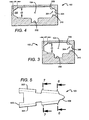
- the rear aperture is clearly seen in FIG. 4 .
- the overall shape is similar to that of the front aperture, but in the preferred embodiment it is significant that the dimensions d3 and d4 of the recessed side troughs at section line 4 are smaller than the corresponding dimensions (d1 and d2) of the front aperture.
- the troughs thus flare slightly outward, moving from rear to front aperture.
- the effect is to define two cable channels 302 and 304, which flare in a hornlike manner, slightly outward moving from rear to front (in the opposite direction from the taper of the overall passage 104 and plug 106).
- the flare is suitably linear, due to the generally plane surfaces defining the channel. This unusual forward-flaring channel design has been found unexpectedly advantageous in securing polymer cables at high tension.
- the plug 106 is shown separately in FIGs 5 , 6 and 7 .
- the plug is generally trapezoidal in plan ( FIG. 5 ), having sides 502 and 504 that taper from a wider rear end 506 to a narrow front end 508.
- a forward sectional view ( FIG. 6 ) reveals that the sides (at least one) have beveled recessed faces that describe a groove or trough running the length of the plug.
- Said groove or trough has a plurality of plane faces 312, 314 and 316 meeting at concave dihedral angles, and complementary to those of the body 102 as described above.
- Rearward section ( FIG. 7 ) is similar in shape. As with the corresponding dimensions of the body, d1 is greater than d3; similarly, d2 is greater than d4, defining forward flaring troughs.
- each channel should not be confused with the angle defined between the channels, which is converging moving from the rear to the front of the body.
- the channels may generally converge toward one another at an angle of approximately 12 degrees.
- FIG. 8 shows plug 106 inserted into the body 102.
- Plug 106 has recessed side walls 312, 314, and 316 which are generally imitate the side walls of the passage, forming two bevelled grooves or troughs (one in each side of the plug).
- the recessed side walls 306-310) act in opposition to the complementary recessed walls in the plug (312-316), both pairs of troughs in opposition defining two channels 302 and 304 for receiving the cable.
- the concave troughs of the body oppose the concave grooves of the plug in such a way that they form at least one (preferably two) through channels 302 and 304.
- the through channels thus defined have a polygonal (preferably generally hexagonal) cross section.
- the channels are generally hexagonal channels in the sense that their cross section is hexagonal at any cross plane. It is not necessary that the channel be precisely hexagonal or that the angles be exactly 60 degrees; nor is it necessary that the sides be equal.
- the hexagonal symmetry is only approximate, being in general broken by a gap 510 between plug and body troughs.
- the recessed troughs or grooves in the plug and body in opposition define at least one channel which is prismoidal.
- the channel approximates a frustrum of a polygonal pyramid with the wider portion disposed forward (as previously defined). More specifically, the channel preferably approximates a frustrum of a hexagonal pyramid.
- a guide rail 108 may project from the plug to assist alignment with the guide groove 110 in the body 102.
- the concave faces defining the channels are not precisely parallel with the channel axis. In fact, the channels are flared from a wider front channel dimension to a narrower rear dimension, as discussed above.
- FIG. 9 also displays the taper of the cable channels toward a wider forward aperture, from a narrower rearward aperture (notwithstanding that the plug and the passage as a whole taper toward a narrower forward aperture).
- the inventors have discovered that the unusual taper of the polygonal channels (from wider front to narrower back) in connection with a wedge-like plug tapering in the opposite sense, permits secure gripping of sheathed polymer cables at load tensions in the range up to 400 lbs (1800 N) for a 1.5 mm diameter polymer cable, without slippage, cutting of the cable, or abrasion of the jacket. Furthermore, the tension of the cable maintains the secure grip of the cable lock by tending to draw the wedge-like plug into the tapered channel. The cable lock is thus self-locking and retains the plug unless it is very forcibly extracted. In a preferred embodiment (with two cable strands) the plug tends to self-center in the body.
- the gripping power of the reverse-tapered channel is found to be superior to a channels tapered in the forward, wedging direction, without cutting the cable at high loads.
- the inventors believe that the unusual reverse-tapered channels act to better distribute the frictional load across the gripped section of cable, in the presence of cable deformation under tension.
- the degree of flare of the channels is found to significantly affect the effectiveness of the cord lock according to the invention.
- the flare should be (in a forward direction) less than 2 degrees but more than zero (0 degrees). More preferably, the convergence should 1 degree or less. Most preferably, the convergence should be 0.5 degrees or less (but more than zero).
- This flare is measured as the angle ⁇ between opposite faces of the polyhedral pyramid which would be defined by extending the channel walls backward to an imaginary vertex. The flare could also be measured by percent increase in cross sectional area, divided by length of the channel.
- the preferred increase in cross sectional area is up to a twenty per cent increase from the back to the front aperture, over a linear length (in a particular embodiment) of approximately .385 inches.
- the cross sectional area of each hexagonal channel increases from .0021 to .0025 square inches over approximately .385 inches linear run.
- the preferred cross sectional geometry is presently believed to be hexagonal; but other shapes could also be used, including but not limited to other polyhedral cross sections or curved cross sections.
- the channels approximate a frustrum of a hexagonal pyramid wherein the angle between opposite faces converges with an angle of less than 2 degrees.
- the plug 106 has a height dimensions that are slightly less than the height dimension of the passage 104 into which the plug is inserted. ("Height is shown vertically in FIGs. 3, 4 , 6, 7 and 8 ). This provides a slight clearance between the plug 106 and the walls of passage 104. The clearance is visible in FIG. 8 as a gap between plug and the internal walls of the passage 104 in body 102. Most preferably, the gap or clearance completely envelops the plug and all of its features such that the plug can "float" in the passage without contact between the plug and the interior walls of passage 104, The plug is centered and caused to float thusly by the compressed cable 114 when it is retained in the channels 302 and 304. The expansive radial pressures of the compressed cable push in opposition, tending to center the plug.
- the small clearance between plug and passage is desirable because it reduces or eliminates wear, which might otherwise occur from friction of plug surfaces against the passage walls. Such wear can produce very tiny particles of debris, which are undesirable in surgical implant locations.
- a symmetrical and generally balanced channel shape is advantageous.
- the center of compression in each arm of the cable should be disposed symmetrically, and preferably centered in the channel.
- Substantial symmetry of the channels such as that of the regular polyhedral channel in the figures, encourages the plug to float to a suspended, stable centered position. Such a centered position will in turn reduce or eliminate surface wear within the device.
- Bilateral symmetry of the body and plug are also desirable, for the same reasons.
- the vertical dimensions of the interior passage exceed the vertical dimensions of the plug by .005 inches (at the deepest part of the groove 202 and near the rear aperture) and approximately .004 inches elsewhere (for the substantially plane top and bottom of the plug).
- This clearance will be shared between the top gap and the bottom gap, as the pressure of the compressed cable causes the plug to float to an equilibrium position.
- the quantitative measurement of the clearance is approximate, and given as an example. Machining tolerances or particular design considerations may cause the clearance to vary considerably from these exemplary measurements.
- the body and plug are suitably made from a high strength, rigid material such as Titanium or an alloy thereof.
- a high strength, rigid material such as Titanium or an alloy thereof.
- Other alloys or materials, including polymers, may be used in some embodiments.
- Titanium or stainless steel alloys are currently thought to be preferably in medical implant applications.
- the pieces may be manufactured by EDM (electrical discharge machining), by metal injection molding, or other methods, preferably taking care to properly texture the channels as discussed above.
- the channels 302 and 304 should not be machined smooth, but rather should have some degree of texture or grain.
- the channels can be machined by Electrical discharge machining (EDM) which will leave sufficient texture to engage polymer fiber securely.
- EDM Electrical discharge machining
- the channel can be abraded by glass bead finish process.
- the channel should be free from sharp teeth or aggressive barbs (such as those characterizing some prior cord locks, see U.S. patent number 4156574 ).
- the texture has been found significant for holding smooth jacketed polymer cables, in some applications the texture may not be absolutely required.
- Another aspect of the invention is a system of cable and cable lock, suitable for establishing and sustaining high tensile connection and adaptable for surgical use.
- the system comprises essentially the cable lock described above in concert with a strong and elastic cable.
- the cable is an engineered polymer cable comprising at least one core filament (suitably nylon), coaxially surrounded by a woven jacket.
- the braided jacket preferably comprises woven fibers of an ultra-high molecular weight polymer material such as that sold by Honeywell Corp. (Allantown, PA) under the trade name "spectra"TM.
- the cable clamp as described above is used in concert with a polymer cable capable of achieving elongation which increases the polymer cable by a percentage between 60 and 140 per cent of its original length, at a working tension up to approximately 800 Newtons.
- the working force is commonly doubled by doubling the cable as shown in FIGs. 1 and 10 .
- a suitable cable can be engineered from nylon core and SpectraTM jacket.
- Preferably the jacket should be coated with a coating to enhance grip and insulate the cable from biological hydrolysis.
- a cable clamp in accordance with the invention is found to be effective at tensions up to 350 lbs (1600 N) per strand. Note that the tensions have been given in lbs for each cable end.
- the cable has both ends engaged (one on each side of the wedged plug) and thus the clamp can support double the tension of a single cable.
- the cable ends 126 and 128 comprise two ends of a looped cable, doubled at the end. The doubled end can be retained by the body by threading the ends through the holes 122 and 124 and roughly centering the body near the middle of the cable, as shown in FIG. 1 .
- the body thus retains in a through bore the middle of a doubled cable.
- the doubled ends can be passed around a system, tensioned, and clamped by the tapered plug and body of the clamp as shown (and as previously described).
- Such an arrangement is a convenient method of providing cerclage for surgical procedures, for example in compressing a fractured femur (with or without a plate to align the bones).
- the invention also includes a method of retaining a high tension cable suitable for use to attach cables during surgery according to claim 14.
- a cable is included in a cable clamp as described above: having at least one tapered channel between a body and a slidable plug, with a free end emerging from a rear end of the body, and a working end emerging from a forward end of said body.
- the slidable plug and body are tapered and adapted to constrict around said cable as the slidable plug slides toward a forward end of the body.
- the cable is received in a tapered channel which flares outward in the forward direction. Tension is then applied to the cable in a forward direction, while applying reactive force to the body in the opposite direction.
- the plug responds the cable tension by sliding forward, wedging securely in the tapered body and engaging the cable in a channel.
- the channel has a forward flare, opening in the direction toward the source of tension.
- the wedge and body constrict in response to sliding of the plug in the forward direction; nevertheless, the cable channel flares outward in the forward direction.
Landscapes
- Health & Medical Sciences (AREA)
- Engineering & Computer Science (AREA)
- General Engineering & Computer Science (AREA)
- Orthopedic Medicine & Surgery (AREA)
- Surgery (AREA)
- Mechanical Engineering (AREA)
- Life Sciences & Earth Sciences (AREA)
- Neurology (AREA)
- Nuclear Medicine, Radiotherapy & Molecular Imaging (AREA)
- Biomedical Technology (AREA)
- Heart & Thoracic Surgery (AREA)
- Medical Informatics (AREA)
- Molecular Biology (AREA)
- Animal Behavior & Ethology (AREA)
- General Health & Medical Sciences (AREA)
- Public Health (AREA)
- Veterinary Medicine (AREA)
- Surgical Instruments (AREA)
Priority Applications (1)
| Application Number | Priority Date | Filing Date | Title |
|---|---|---|---|
| PL05763350T PL1781961T3 (pl) | 2004-06-09 | 2005-06-08 | Blokada mocno naprężonej linki chirurgicznej |
Applications Claiming Priority (2)
| Application Number | Priority Date | Filing Date | Title |
|---|---|---|---|
| US57861104P | 2004-06-09 | 2004-06-09 | |
| PCT/US2005/020117 WO2005124187A2 (en) | 2004-06-09 | 2005-06-08 | High tension, surgical cable lock |
Publications (3)
| Publication Number | Publication Date |
|---|---|
| EP1781961A2 EP1781961A2 (en) | 2007-05-09 |
| EP1781961A4 EP1781961A4 (en) | 2010-07-21 |
| EP1781961B1 true EP1781961B1 (en) | 2013-05-22 |
Family
ID=35510358
Family Applications (1)
| Application Number | Title | Priority Date | Filing Date |
|---|---|---|---|
| EP05763350.5A Expired - Lifetime EP1781961B1 (en) | 2004-06-09 | 2005-06-08 | High tension, surgical cable lock |
Country Status (8)
| Country | Link |
|---|---|
| US (1) | US7207090B2 (da) |
| EP (1) | EP1781961B1 (da) |
| JP (1) | JP4829236B2 (da) |
| DK (1) | DK1781961T3 (da) |
| ES (1) | ES2423431T3 (da) |
| PL (1) | PL1781961T3 (da) |
| PT (1) | PT1781961E (da) |
| WO (1) | WO2005124187A2 (da) |
Families Citing this family (37)
| Publication number | Priority date | Publication date | Assignee | Title |
|---|---|---|---|---|
| FR2842724B1 (fr) | 2002-07-23 | 2005-05-27 | Spine Next Sa | Systeme de fixation vertebrale |
| FR2890850B1 (fr) | 2005-09-20 | 2009-04-17 | Abbott Spine Sa | Systeme de fixation vertebrale |
| FR2890851B1 (fr) | 2005-09-21 | 2008-06-20 | Abbott Spine Sa | Ancillaire de mise en tension d'un lien souple. |
| EP2047813A1 (en) | 2007-10-11 | 2009-04-15 | Abbott Spine | Bone fixing system and method of use |
| FR2921248A1 (fr) | 2007-09-25 | 2009-03-27 | Abbott Spine Sa | Dispositif de serrage de deux portions d'une tresse et implant intervertebral comprenant une cale, une tresse et un tel dispositif de serrage |
| US8128635B2 (en) | 2007-10-23 | 2012-03-06 | Zimmer Spine S.A.S. | Bone fixation tensioning tool and method |
| CN103251447B (zh) * | 2007-11-13 | 2016-01-27 | 新特斯有限责任公司 | 微创环扎系统 |
| US20090248077A1 (en) * | 2008-03-31 | 2009-10-01 | Derrick William Johns | Hybrid dynamic stabilization |
| ATE515239T1 (de) * | 2008-04-24 | 2011-07-15 | Zimmer Spine | System zur stabilisierung von mindestens einem abschnitt der wirbelsäule |
| AU2009248781A1 (en) * | 2008-05-20 | 2009-11-26 | Zimmer Spine | System for stabilizing at least three vertebrae |
| ES2471015T3 (es) | 2009-06-02 | 2014-06-25 | Kinamed, Inc. | Sistema tensor de cable quirúrgico |
| WO2011147449A1 (en) * | 2010-05-26 | 2011-12-01 | Stoba Ag | Cable seal assembly |
| US8968357B2 (en) | 2010-09-07 | 2015-03-03 | Covidien Lp | Collet based locking mechanism |
| US20120073087A1 (en) * | 2010-09-27 | 2012-03-29 | Briganti Robert A | Low friction cord lock |
| US9522026B2 (en) | 2011-02-17 | 2016-12-20 | Matthew N. Songer | Cable system for surgical application |
| EP2755582B1 (en) | 2011-09-14 | 2023-07-26 | OrthoPediatrics Corp. | Tether clamp and implantation system |
| US20140058445A1 (en) * | 2012-05-14 | 2014-02-27 | Terry Mattchen | High tension suture anchor |
| US20140148854A1 (en) | 2012-11-28 | 2014-05-29 | Zimmer Spine, Inc. | Vertebral fixation system |
| US11446062B2 (en) | 2013-03-14 | 2022-09-20 | Kinamed, Inc. | Vector compression system |
| US10383658B2 (en) | 2013-03-14 | 2019-08-20 | Poly-4 Group, Lp | Vector compression system |
| EP2967691A4 (en) | 2013-03-15 | 2016-12-14 | Songer Matthew N | DEVICE FOR CABLE FIXING |
| US10258400B2 (en) | 2013-03-15 | 2019-04-16 | J. M. Longyear Manufacturing Llc | Cable fixation device, instruments, and methods |
| US10206729B2 (en) | 2014-12-30 | 2019-02-19 | Kinamed, Inc. | Self-locking cable gripper |
| US10143506B2 (en) | 2016-03-17 | 2018-12-04 | Arthrex, Inc. | Method and system for providing a suture wrap cerclage |
| US10314628B2 (en) | 2016-03-17 | 2019-06-11 | Arthrex, Inc. | Method and system for providing a suture wrap cerclage |
| AU2017302286B2 (en) | 2016-07-26 | 2022-08-18 | Orthopediatrics Corp. | Orthopedic tethered implants and system |
| AU2018209968B2 (en) * | 2017-01-19 | 2020-10-22 | Kinamed, Inc. | Sternotomy closure technique using polymeric cable |
| US20180317611A1 (en) * | 2017-05-03 | 2018-11-08 | National Molding Llc | Redirect buckle |
| US11071569B2 (en) | 2017-08-10 | 2021-07-27 | Ortho Development Corporation | Nesting tether clamping assemblies and related methods and apparatus |
| US11051857B2 (en) | 2017-08-10 | 2021-07-06 | Ortho Development Corporation | Tether clamping assemblies and related methods and apparatus |
| EP3681422A1 (en) | 2017-09-15 | 2020-07-22 | DSM IP Assets B.V. | Medical fixation device for polymer cables |
| EP3581131B8 (en) | 2018-06-15 | 2023-03-01 | Stryker European Operations Holdings LLC | Trochanter plates |
| US11819255B2 (en) | 2019-10-07 | 2023-11-21 | Ortho Development Corporation | Tether tensioning instrumentation and related methods |
| WO2021127300A1 (en) | 2019-12-18 | 2021-06-24 | Dsm Ip Assets B.V. | Orthopedic screws and prostheses for use with polymer cables |
| US12402926B2 (en) | 2021-02-26 | 2025-09-02 | Arthrex, Inc. | System and method for providing a bone cerclage |
| US11844511B2 (en) | 2021-07-08 | 2023-12-19 | Arthrex, Inc. | Surgical system and method permitting percutaneous insertion of anchors |
| JP2025151682A (ja) * | 2024-03-28 | 2025-10-09 | 東京製綱株式会社 | 索体引留金具 |
Family Cites Families (9)
| Publication number | Priority date | Publication date | Assignee | Title |
|---|---|---|---|---|
| FR784791A (fr) * | 1934-04-20 | 1935-07-24 | Dispositif d'attache des câbles, tiges ou similaires susceptible de constituer une connexion pour des câbles ou des fils électriques | |
| US3953144A (en) * | 1974-02-04 | 1976-04-27 | Boden Ogden W | Cord lock with both sharp and dull teeth |
| FR2350427A1 (fr) | 1976-05-07 | 1977-12-02 | Clavel Alain | Pilonneuse de chantier |
| US4059333A (en) * | 1977-01-05 | 1977-11-22 | Amp Incorporated | Electrical connector |
| US4156574A (en) | 1978-02-06 | 1979-05-29 | Boden Ogden W | Cord lock with self locking spring feelers |
| US5145420A (en) * | 1991-05-31 | 1992-09-08 | Counsel Eugene F | Electrical wire connector |
| US5244422A (en) * | 1992-09-04 | 1993-09-14 | The Whitaker Corporation | Wedge connector |
| US6589246B1 (en) | 2001-04-26 | 2003-07-08 | Poly-4 Medical, Inc. | Method of applying an active compressive force continuously across a fracture |
| US6842949B2 (en) * | 2003-05-19 | 2005-01-18 | Robert E. Warren | U-shaped wire rope clamp |
-
2005
- 2005-06-08 PT PT57633505T patent/PT1781961E/pt unknown
- 2005-06-08 ES ES05763350T patent/ES2423431T3/es not_active Expired - Lifetime
- 2005-06-08 US US11/147,685 patent/US7207090B2/en not_active Expired - Lifetime
- 2005-06-08 EP EP05763350.5A patent/EP1781961B1/en not_active Expired - Lifetime
- 2005-06-08 DK DK05763350.5T patent/DK1781961T3/da active
- 2005-06-08 WO PCT/US2005/020117 patent/WO2005124187A2/en not_active Ceased
- 2005-06-08 PL PL05763350T patent/PL1781961T3/pl unknown
- 2005-06-08 JP JP2007527685A patent/JP4829236B2/ja not_active Expired - Lifetime
Also Published As
| Publication number | Publication date |
|---|---|
| ES2423431T3 (es) | 2013-09-20 |
| WO2005124187A3 (en) | 2006-12-21 |
| DK1781961T3 (da) | 2013-08-26 |
| US20050273983A1 (en) | 2005-12-15 |
| JP2008502867A (ja) | 2008-01-31 |
| PL1781961T3 (pl) | 2013-10-31 |
| US7207090B2 (en) | 2007-04-24 |
| WO2005124187A2 (en) | 2005-12-29 |
| EP1781961A2 (en) | 2007-05-09 |
| JP4829236B2 (ja) | 2011-12-07 |
| PT1781961E (pt) | 2013-06-24 |
| EP1781961A4 (en) | 2010-07-21 |
Similar Documents
| Publication | Publication Date | Title |
|---|---|---|
| US7207090B2 (en) | High tension, surgical cable lock | |
| US12076055B2 (en) | Pivotal bone anchor assembly with favored-angle receiver having upper tool engagement grooves and break-off extensions | |
| US6475218B2 (en) | Spinal implant for an osteosynthesis device | |
| US6099527A (en) | Bone protector and method | |
| US11413077B2 (en) | Bone plate having a connector and a connector for a surgical loop | |
| US5649927A (en) | Cable crimp system | |
| US6017347A (en) | Wire clamp assembly | |
| CN101917920B (zh) | 微创环扎系统 | |
| AU2001266265A1 (en) | Spinal implant for an osteosynthesis device | |
| US20040162560A1 (en) | Implant device including threaded locking mechanism | |
| US8523915B2 (en) | Friction set screw for use with spinal implant systems | |
| AU2015372512B2 (en) | Self-locking cable gripper | |
| AU2011204541A1 (en) | Vertebral attachment device | |
| US10433879B2 (en) | Device for attaching a flat band on a bone part | |
| EP2245334B1 (en) | Cable termination with an elliptical wall profile | |
| US11998252B2 (en) | System and method for bone fixation | |
| US20190290257A1 (en) | High tension suture anchor |
Legal Events
| Date | Code | Title | Description |
|---|---|---|---|
| PUAI | Public reference made under article 153(3) epc to a published international application that has entered the european phase |
Free format text: ORIGINAL CODE: 0009012 |
|
| 17P | Request for examination filed |
Effective date: 20070105 |
|
| AK | Designated contracting states |
Kind code of ref document: A2 Designated state(s): AT BE BG CH CY CZ DE DK EE ES FI FR GB GR HU IE IS IT LI LT LU MC NL PL PT RO SE SI SK TR |
|
| AX | Request for extension of the european patent |
Extension state: AL BA HR LV MK YU |
|
| RIC1 | Information provided on ipc code assigned before grant |
Ipc: A41B 1/04 20060101AFI20070521BHEP |
|
| DAX | Request for extension of the european patent (deleted) | ||
| A4 | Supplementary search report drawn up and despatched |
Effective date: 20100617 |
|
| 17Q | First examination report despatched |
Effective date: 20110217 |
|
| GRAP | Despatch of communication of intention to grant a patent |
Free format text: ORIGINAL CODE: EPIDOSNIGR1 |
|
| GRAP | Despatch of communication of intention to grant a patent |
Free format text: ORIGINAL CODE: EPIDOSNIGR1 |
|
| GRAS | Grant fee paid |
Free format text: ORIGINAL CODE: EPIDOSNIGR3 |
|
| GRAA | (expected) grant |
Free format text: ORIGINAL CODE: 0009210 |
|
| AK | Designated contracting states |
Kind code of ref document: B1 Designated state(s): AT BE BG CH CY CZ DE DK EE ES FI FR GB GR HU IE IS IT LI LT LU MC NL PL PT RO SE SI SK TR |
|
| REG | Reference to a national code |
Ref country code: GB Ref legal event code: FG4D |
|
| REG | Reference to a national code |
Ref country code: CH Ref legal event code: EP |
|
| REG | Reference to a national code |
Ref country code: CH Ref legal event code: NV Representative=s name: KIRKER AND CIE S.A., CH |
|
| REG | Reference to a national code |
Ref country code: AT Ref legal event code: REF Ref document number: 612702 Country of ref document: AT Kind code of ref document: T Effective date: 20130615 |
|
| REG | Reference to a national code |
Ref country code: IE Ref legal event code: FG4D |
|
| REG | Reference to a national code |
Ref country code: PT Ref legal event code: SC4A Free format text: AVAILABILITY OF NATIONAL TRANSLATION Effective date: 20130612 |
|
| REG | Reference to a national code |
Ref country code: DE Ref legal event code: R096 Ref document number: 602005039708 Country of ref document: DE Effective date: 20130718 |
|
| REG | Reference to a national code |
Ref country code: SE Ref legal event code: TRGR |
|
| REG | Reference to a national code |
Ref country code: DK Ref legal event code: T3 |
|
| REG | Reference to a national code |
Ref country code: NL Ref legal event code: T3 |
|
| REG | Reference to a national code |
Ref country code: ES Ref legal event code: FG2A Ref document number: 2423431 Country of ref document: ES Kind code of ref document: T3 Effective date: 20130920 |
|
| REG | Reference to a national code |
Ref country code: GR Ref legal event code: EP Ref document number: 20130401545 Country of ref document: GR Effective date: 20130829 |
|
| PG25 | Lapsed in a contracting state [announced via postgrant information from national office to epo] |
Ref country code: SI Free format text: LAPSE BECAUSE OF FAILURE TO SUBMIT A TRANSLATION OF THE DESCRIPTION OR TO PAY THE FEE WITHIN THE PRESCRIBED TIME-LIMIT Effective date: 20130522 Ref country code: IS Free format text: LAPSE BECAUSE OF FAILURE TO SUBMIT A TRANSLATION OF THE DESCRIPTION OR TO PAY THE FEE WITHIN THE PRESCRIBED TIME-LIMIT Effective date: 20130922 Ref country code: FI Free format text: LAPSE BECAUSE OF FAILURE TO SUBMIT A TRANSLATION OF THE DESCRIPTION OR TO PAY THE FEE WITHIN THE PRESCRIBED TIME-LIMIT Effective date: 20130522 |
|
| REG | Reference to a national code |
Ref country code: PL Ref legal event code: T3 |
|
| PG25 | Lapsed in a contracting state [announced via postgrant information from national office to epo] |
Ref country code: BG Free format text: LAPSE BECAUSE OF FAILURE TO SUBMIT A TRANSLATION OF THE DESCRIPTION OR TO PAY THE FEE WITHIN THE PRESCRIBED TIME-LIMIT Effective date: 20130822 |
|
| PG25 | Lapsed in a contracting state [announced via postgrant information from national office to epo] |
Ref country code: EE Free format text: LAPSE BECAUSE OF FAILURE TO SUBMIT A TRANSLATION OF THE DESCRIPTION OR TO PAY THE FEE WITHIN THE PRESCRIBED TIME-LIMIT Effective date: 20130522 Ref country code: SK Free format text: LAPSE BECAUSE OF FAILURE TO SUBMIT A TRANSLATION OF THE DESCRIPTION OR TO PAY THE FEE WITHIN THE PRESCRIBED TIME-LIMIT Effective date: 20130522 Ref country code: CZ Free format text: LAPSE BECAUSE OF FAILURE TO SUBMIT A TRANSLATION OF THE DESCRIPTION OR TO PAY THE FEE WITHIN THE PRESCRIBED TIME-LIMIT Effective date: 20130522 |
|
| PG25 | Lapsed in a contracting state [announced via postgrant information from national office to epo] |
Ref country code: RO Free format text: LAPSE BECAUSE OF FAILURE TO SUBMIT A TRANSLATION OF THE DESCRIPTION OR TO PAY THE FEE WITHIN THE PRESCRIBED TIME-LIMIT Effective date: 20130522 |
|
| PLBE | No opposition filed within time limit |
Free format text: ORIGINAL CODE: 0009261 |
|
| STAA | Information on the status of an ep patent application or granted ep patent |
Free format text: STATUS: NO OPPOSITION FILED WITHIN TIME LIMIT |
|
| 26N | No opposition filed |
Effective date: 20140225 |
|
| REG | Reference to a national code |
Ref country code: HU Ref legal event code: AG4A Ref document number: E018765 Country of ref document: HU |
|
| REG | Reference to a national code |
Ref country code: DE Ref legal event code: R097 Ref document number: 602005039708 Country of ref document: DE Effective date: 20140225 |
|
| REG | Reference to a national code |
Ref country code: DE Ref legal event code: R082 Ref document number: 602005039708 Country of ref document: DE Representative=s name: LIPPERT STACHOW PATENTANWAELTE RECHTSANWAELTE , DE Ref country code: DE Ref legal event code: R082 Ref document number: 602005039708 Country of ref document: DE Representative=s name: PATENTANWAELTE LIPPERT, STACHOW & PARTNER, DE |
|
| PG25 | Lapsed in a contracting state [announced via postgrant information from national office to epo] |
Ref country code: CY Free format text: LAPSE BECAUSE OF FAILURE TO SUBMIT A TRANSLATION OF THE DESCRIPTION OR TO PAY THE FEE WITHIN THE PRESCRIBED TIME-LIMIT Effective date: 20130522 |
|
| REG | Reference to a national code |
Ref country code: FR Ref legal event code: PLFP Year of fee payment: 12 |
|
| PGFP | Annual fee paid to national office [announced via postgrant information from national office to epo] |
Ref country code: GR Payment date: 20160614 Year of fee payment: 12 Ref country code: MC Payment date: 20160609 Year of fee payment: 12 Ref country code: LU Payment date: 20160610 Year of fee payment: 12 |
|
| PGFP | Annual fee paid to national office [announced via postgrant information from national office to epo] |
Ref country code: LT Payment date: 20160603 Year of fee payment: 12 Ref country code: HU Payment date: 20160629 Year of fee payment: 12 Ref country code: PL Payment date: 20160603 Year of fee payment: 12 Ref country code: DK Payment date: 20160610 Year of fee payment: 12 |
|
| REG | Reference to a national code |
Ref country code: FR Ref legal event code: PLFP Year of fee payment: 13 |
|
| REG | Reference to a national code |
Ref country code: LT Ref legal event code: MM4D Effective date: 20170608 |
|
| REG | Reference to a national code |
Ref country code: DK Ref legal event code: EBP Effective date: 20170630 |
|
| PG25 | Lapsed in a contracting state [announced via postgrant information from national office to epo] |
Ref country code: LT Free format text: LAPSE BECAUSE OF NON-PAYMENT OF DUE FEES Effective date: 20170608 Ref country code: MC Free format text: LAPSE BECAUSE OF NON-PAYMENT OF DUE FEES Effective date: 20170630 |
|
| PG25 | Lapsed in a contracting state [announced via postgrant information from national office to epo] |
Ref country code: HU Free format text: LAPSE BECAUSE OF NON-PAYMENT OF DUE FEES Effective date: 20170609 Ref country code: LU Free format text: LAPSE BECAUSE OF NON-PAYMENT OF DUE FEES Effective date: 20170608 |
|
| PG25 | Lapsed in a contracting state [announced via postgrant information from national office to epo] |
Ref country code: GR Free format text: LAPSE BECAUSE OF NON-PAYMENT OF DUE FEES Effective date: 20180111 |
|
| REG | Reference to a national code |
Ref country code: FR Ref legal event code: PLFP Year of fee payment: 14 |
|
| PG25 | Lapsed in a contracting state [announced via postgrant information from national office to epo] |
Ref country code: DK Free format text: LAPSE BECAUSE OF NON-PAYMENT OF DUE FEES Effective date: 20170630 |
|
| PG25 | Lapsed in a contracting state [announced via postgrant information from national office to epo] |
Ref country code: PL Free format text: LAPSE BECAUSE OF NON-PAYMENT OF DUE FEES Effective date: 20170608 |
|
| PGFP | Annual fee paid to national office [announced via postgrant information from national office to epo] |
Ref country code: ES Payment date: 20200701 Year of fee payment: 16 |
|
| REG | Reference to a national code |
Ref country code: ES Ref legal event code: FD2A Effective date: 20220803 |
|
| PG25 | Lapsed in a contracting state [announced via postgrant information from national office to epo] |
Ref country code: ES Free format text: LAPSE BECAUSE OF NON-PAYMENT OF DUE FEES Effective date: 20210609 |
|
| PGFP | Annual fee paid to national office [announced via postgrant information from national office to epo] |
Ref country code: NL Payment date: 20240514 Year of fee payment: 20 |
|
| PGFP | Annual fee paid to national office [announced via postgrant information from national office to epo] |
Ref country code: IE Payment date: 20240527 Year of fee payment: 20 |
|
| PGFP | Annual fee paid to national office [announced via postgrant information from national office to epo] |
Ref country code: GB Payment date: 20240509 Year of fee payment: 20 |
|
| PGFP | Annual fee paid to national office [announced via postgrant information from national office to epo] |
Ref country code: DE Payment date: 20240509 Year of fee payment: 20 |
|
| PGFP | Annual fee paid to national office [announced via postgrant information from national office to epo] |
Ref country code: AT Payment date: 20240527 Year of fee payment: 20 |
|
| PGFP | Annual fee paid to national office [announced via postgrant information from national office to epo] |
Ref country code: FR Payment date: 20240509 Year of fee payment: 20 |
|
| PGFP | Annual fee paid to national office [announced via postgrant information from national office to epo] |
Ref country code: PT Payment date: 20240527 Year of fee payment: 20 |
|
| PGFP | Annual fee paid to national office [announced via postgrant information from national office to epo] |
Ref country code: TR Payment date: 20240514 Year of fee payment: 20 Ref country code: SE Payment date: 20240610 Year of fee payment: 20 Ref country code: BE Payment date: 20240514 Year of fee payment: 20 |
|
| PGFP | Annual fee paid to national office [announced via postgrant information from national office to epo] |
Ref country code: IT Payment date: 20240611 Year of fee payment: 20 |
|
| PGFP | Annual fee paid to national office [announced via postgrant information from national office to epo] |
Ref country code: CH Payment date: 20240701 Year of fee payment: 20 |
|
| REG | Reference to a national code |
Ref country code: DE Ref legal event code: R071 Ref document number: 602005039708 Country of ref document: DE |
|
| REG | Reference to a national code |
Ref country code: NL Ref legal event code: MK Effective date: 20250607 |
|
| REG | Reference to a national code |
Ref country code: CH Ref legal event code: PL |
|
| REG | Reference to a national code |
Ref country code: GB Ref legal event code: PE20 Expiry date: 20250607 |
|
| PG25 | Lapsed in a contracting state [announced via postgrant information from national office to epo] |
Ref country code: GB Free format text: LAPSE BECAUSE OF EXPIRATION OF PROTECTION Effective date: 20250607 |
|
| REG | Reference to a national code |
Ref country code: AT Ref legal event code: MK07 Ref document number: 612702 Country of ref document: AT Kind code of ref document: T Effective date: 20250608 |
|
| PG25 | Lapsed in a contracting state [announced via postgrant information from national office to epo] |
Ref country code: PT Free format text: LAPSE BECAUSE OF EXPIRATION OF PROTECTION Effective date: 20250623 |
|
| REG | Reference to a national code |
Ref country code: SE Ref legal event code: EUG |
|
| REG | Reference to a national code |
Ref country code: IE Ref legal event code: MK9A |
|
| REG | Reference to a national code |
Ref country code: BE Ref legal event code: MK Effective date: 20250608 |
|
| PG25 | Lapsed in a contracting state [announced via postgrant information from national office to epo] |
Ref country code: IE Free format text: LAPSE BECAUSE OF EXPIRATION OF PROTECTION Effective date: 20250608 |