EP1781981B1 - Dispositif et procede de securite pour un robot industriel - Google Patents
Dispositif et procede de securite pour un robot industriel Download PDFInfo
- Publication number
- EP1781981B1 EP1781981B1 EP05787611.2A EP05787611A EP1781981B1 EP 1781981 B1 EP1781981 B1 EP 1781981B1 EP 05787611 A EP05787611 A EP 05787611A EP 1781981 B1 EP1781981 B1 EP 1781981B1
- Authority
- EP
- European Patent Office
- Prior art keywords
- safety
- industrial robot
- zone
- sensors
- sensor
- Prior art date
- Legal status (The legal status is an assumption and is not a legal conclusion. Google has not performed a legal analysis and makes no representation as to the accuracy of the status listed.)
- Expired - Lifetime
Links
Images

Classifications
-
- F—MECHANICAL ENGINEERING; LIGHTING; HEATING; WEAPONS; BLASTING
- F16—ENGINEERING ELEMENTS AND UNITS; GENERAL MEASURES FOR PRODUCING AND MAINTAINING EFFECTIVE FUNCTIONING OF MACHINES OR INSTALLATIONS; THERMAL INSULATION IN GENERAL
- F16P—SAFETY DEVICES IN GENERAL; SAFETY DEVICES FOR PRESSES
- F16P3/00—Safety devices acting in conjunction with the control or operation of a machine; Control arrangements requiring the simultaneous use of two or more parts of the body
- F16P3/12—Safety devices acting in conjunction with the control or operation of a machine; Control arrangements requiring the simultaneous use of two or more parts of the body with means, e.g. feelers, which in case of the presence of a body part of a person in or near the danger zone influence the control or operation of the machine
- F16P3/14—Safety devices acting in conjunction with the control or operation of a machine; Control arrangements requiring the simultaneous use of two or more parts of the body with means, e.g. feelers, which in case of the presence of a body part of a person in or near the danger zone influence the control or operation of the machine the means being photocells or other devices sensitive without mechanical contact
- F16P3/147—Safety devices acting in conjunction with the control or operation of a machine; Control arrangements requiring the simultaneous use of two or more parts of the body with means, e.g. feelers, which in case of the presence of a body part of a person in or near the danger zone influence the control or operation of the machine the means being photocells or other devices sensitive without mechanical contact using electro-magnetic technology, e.g. tags or radar
-
- B—PERFORMING OPERATIONS; TRANSPORTING
- B25—HAND TOOLS; PORTABLE POWER-DRIVEN TOOLS; MANIPULATORS
- B25J—MANIPULATORS; CHAMBERS PROVIDED WITH MANIPULATION DEVICES
- B25J9/00—Program-controlled manipulators
- B25J9/16—Program controls
- B25J9/1674—Program controls characterised by safety, monitoring, diagnostic
- B25J9/1676—Avoiding collision or forbidden zones
-
- F—MECHANICAL ENGINEERING; LIGHTING; HEATING; WEAPONS; BLASTING
- F16—ENGINEERING ELEMENTS AND UNITS; GENERAL MEASURES FOR PRODUCING AND MAINTAINING EFFECTIVE FUNCTIONING OF MACHINES OR INSTALLATIONS; THERMAL INSULATION IN GENERAL
- F16P—SAFETY DEVICES IN GENERAL; SAFETY DEVICES FOR PRESSES
- F16P3/00—Safety devices acting in conjunction with the control or operation of a machine; Control arrangements requiring the simultaneous use of two or more parts of the body
- F16P3/12—Safety devices acting in conjunction with the control or operation of a machine; Control arrangements requiring the simultaneous use of two or more parts of the body with means, e.g. feelers, which in case of the presence of a body part of a person in or near the danger zone influence the control or operation of the machine
- F16P3/14—Safety devices acting in conjunction with the control or operation of a machine; Control arrangements requiring the simultaneous use of two or more parts of the body with means, e.g. feelers, which in case of the presence of a body part of a person in or near the danger zone influence the control or operation of the machine the means being photocells or other devices sensitive without mechanical contact
- F16P3/141—Safety devices acting in conjunction with the control or operation of a machine; Control arrangements requiring the simultaneous use of two or more parts of the body with means, e.g. feelers, which in case of the presence of a body part of a person in or near the danger zone influence the control or operation of the machine the means being photocells or other devices sensitive without mechanical contact using sound propagation, e.g. sonar
-
- F—MECHANICAL ENGINEERING; LIGHTING; HEATING; WEAPONS; BLASTING
- F16—ENGINEERING ELEMENTS AND UNITS; GENERAL MEASURES FOR PRODUCING AND MAINTAINING EFFECTIVE FUNCTIONING OF MACHINES OR INSTALLATIONS; THERMAL INSULATION IN GENERAL
- F16P—SAFETY DEVICES IN GENERAL; SAFETY DEVICES FOR PRESSES
- F16P3/00—Safety devices acting in conjunction with the control or operation of a machine; Control arrangements requiring the simultaneous use of two or more parts of the body
- F16P3/12—Safety devices acting in conjunction with the control or operation of a machine; Control arrangements requiring the simultaneous use of two or more parts of the body with means, e.g. feelers, which in case of the presence of a body part of a person in or near the danger zone influence the control or operation of the machine
- F16P3/14—Safety devices acting in conjunction with the control or operation of a machine; Control arrangements requiring the simultaneous use of two or more parts of the body with means, e.g. feelers, which in case of the presence of a body part of a person in or near the danger zone influence the control or operation of the machine the means being photocells or other devices sensitive without mechanical contact
- F16P3/144—Safety devices acting in conjunction with the control or operation of a machine; Control arrangements requiring the simultaneous use of two or more parts of the body with means, e.g. feelers, which in case of the presence of a body part of a person in or near the danger zone influence the control or operation of the machine the means being photocells or other devices sensitive without mechanical contact using light grids
Definitions
- the invention relates to a device for securing an industrial robot with moving parts according to the preamble of claim 1, as well as a method for securing an industrial robot with moving parts according to the preamble of claim 13.
- the term handling devices are here based on the representation in " Automation technology in manufacturing, 2nd edition 1996, Publisher Europa Lehrstoff, ISBN 3-8085-5152-6, pages 317 to 318 "both mechanically controlled, fixed-programmed so-called pick-and-place devices, for example, devices for loading a press, for the assembly of mass produced or packaging of series products, understood as well as universally applicable motion machine with multiple axes, their movements in terms of motion sequence and Movement path are freely programmable, so-called industrial robots.
- light grids or light fences realized by light barriers or laser scanners, are used. These switch off the machine either immediately or in a safe state, for example in a strongly slowed down driving mode, when an object interrupts the beam path.
- guards obstruct interaction with the machine. In some cases, this may result in safety features being bypassed for convenience. All safety functions are lost, which is an unacceptable state of affairs from a safety point of view.
- a method and an apparatus for controlling a safety-related function of a machine in which a monitoring area is monitored by at least one location- and time-resolved sensor.
- the position, the direction of movement and / or the speed of movement recognized by a person.
- a safety limit or a safety area limits a danger zone and defines a safety distance to the machine.
- the safety-relevant function is triggered, for example an emergency stop.
- the position of the safety boundary and / or the extent of the safety area is variably determined as a function of the position, the direction of movement and / or the speed of movement depending on the situation.
- a location and time-resolved sensor a camera or a laser scanner is used.
- the sensor monitors the entire work area, including the robot arm.
- the position, the direction of movement and / or the movement speed are determined from the sensor signals.
- the concrete method to be used is described in the DE 101 52 543 A1 not described in detail, implicitly it opens up to the skilled person, however, as a highly complex process of real-time image processing, which requires a considerable amount of computing capacity and hardware in the evaluation is required.
- a special object classification system is needed to differentiate between persons and objects, and to tune the safety-related function accordingly. This also requires a considerable additional expenditure of computer power and hardware.
- a system according to the DE 101 52 543 not suitable for portable robot applications, because with each change of position of the robot, the camera must be readjusted and adjusted again, which requires a considerable amount of operator power.
- US 4,804,860 discloses a device for securing an industrial robot according to the preamble of claim 1.
- the safety sensor system comprises non-contact proximity sensors, so that a safety-relevant part of the working space of the handling device is detected by the detection areas of the proximity sensors.
- the security sensor system may also comprise a combination of location- and time-resolved sensors and non-contact proximity sensors, or a combination of location- and time-resolved sensors, non-contact proximity sensors and mechanical limit switches or contact mats.
- the proximity sensors can transmit information about the presence of an object in their respective detection area and about the distance of the object from the respective sensor to the safety controller.
- the proximity sensors suppress information about the presence of an object located in their detection area during the transmission to the safety controller, if the object is in a certain permitted distance range from the proximity sensor.
- the proximity sensors can be proximity switches with variably adjustable switching distances, so that they transmit information about the presence of an object in their respective monitoring area and at a distance corresponding to the respective set switching distance from the proximity sensor to the safety controller.
- each sector is assigned a non-contact proximity sensor or a location and time-resolution sensor as a sector monitoring sensor, the detection area corresponds with its associated sector.
- each sector assigned to a proximity sensor is subdivided into at least two zones of different safety relevance, with the safety relevance corresponding to the distance from the moving parts of the industrial robot.
- each sector associated with a proximity sensor is subdivided into a working zone, a safety zone and a danger zone, such that in the presence of a human being in the danger zone the handling device is switched off and in the presence of a person in the safety zone Handler in a slowed security mode of operation passes.
- the proximity sensors may include ultrasonic sensors or microwave sensors.
- the handling device is a freely programmable industrial robot.
- the safety sensors may very advantageously be attached to the robot base such that the working space of the robot is monitored from the inside outwards from the base. Information about the position of the robot arm can be detected by position sensors on the robot axes and transmitted to the safety controller.
- a safety sensor system for detecting objects in the working space of the industrial robot is used, such that a safety controller cooperates with the industrial robot controller and safety-relevant industrial robot functions are controlled by the safety controller in dependence on signals from the safety sensor ,
- zone-by-zone information about the presence of persons and / or objects in the working space of the industrial robot is determined by the security sensor system and transmitted by the security control.
- zone-by-zone information about the position of the moving part or parts of the industrial robot is transmitted from the industrial robot to the safety controller, and the safety controller, in cooperation with the industrial robot control, makes use of zone-wise safety-relevant industrial robot functions as a function of the two pieces of information controlled.
- the working space of the free programmable industrial robot is further divided into sectors and each sector into at least two zones corresponding to the distance from the mobile robot arm, Safety relevance divided. Information about the position of the robot arm is thereby detected by position sensors on the robot axes and transmitted to the safety controller.
- each sector can be divided into a working zone, a safety zone and a danger zone.
- the robot In the presence of a human detected in the danger zone by the safety sensor, the robot is then turned off, and in the presence of a person in the safety zone, the robot can be controlled by the robot controller in a slowed down safety mode.
- the robot can be controlled by the robot controller into a slowed down safety mode if the presence of a human being in a safety zone is detected by the safety sensor and positioning of the robot arm in the same or an adjacent safety zone is detected by the position sensors, the robot can be controlled by the robot controller into a slowed down safety mode.
- the safety sensor can be selectively mounted so that a targeted monitoring of defined areas is achieved and a self-interference (ie, a triggering of the safety-related robot function by the robot arm itself) or a disturbance to be handled by the robot parts or feeding devices for such parts is not possible.
- a characteristic opening angle of the sensors divides the area to be monitored into sectors.
- the effective range of the sensors can be provided with a window function (realization by electronics), which fades out those areas in which the robot moves or in which the parts to be handled by the robot or feed devices for such parts are located.
- a sensor signal can also be suppressed if the robot moves into the area of a sensor. This can be realized via position-giving sensors, eg position switches, on suitable robot axes. The logical linking of various sensor data takes place in the safety controller.
- the area is filtered out by evaluating the position data by the robot being located. For this purpose, a comparison and comparison of the determined sensor data with the position data, which are supplied by the position-generating sensors of the robot. Furthermore, a considered numerical model of the robot geometry can allow an even more accurate differentiation between true interference and self-interference.
- the environment including the parts to be handled by the robot or supply devices for such parts, may be detected once and the values thus obtained used as a reference. In actual operation, only changes compared to the reference values are taken into account.
- the advantage of the device according to the invention is to provide the possibility of flexible and selective monitoring of the monitored working space of a handling device with the possibility of blanking different areas.
- a security device realized by sensors for the protection of persons is described, this refers to handling systems, portable, mobile or stationary, in particular robots.
- the invention provides a safety sensor system with which the mechanical separating protective device around the handling device is replaced by a more flexible and simpler and safer overall device. The operating personnel and the machine no longer have to be physically separated.
- the safety sensor system according to the invention allows a person to stay in a safety zone of the handling device while the machine is operating in another part of the danger zone. As a result, in addition to the advantages already mentioned, advantages of people can also be combined with those of the machines in one work process. If a person moves into a dangerous area, the robot switches off or slows down to an approved maximum speed, which does not require any safety measures.
- the safety sensor system generally comprises sensors for reliable person detection. It can also be a combination of different sensors eg ultrasound, laser scanner, light curtain, contact mats, radar, etc. In particular, as a further embodiment, a combination of different sensors that monitor the same security area but work on the basis of a different physical principle can be used. This redundancy further enhances security.
- the output signals of the safety sensors are processed in such a way that the sensors can be used compatibly in the industrial sector.
- signal processing electronics can convert the output signal to a standardized analog current or voltage signal which is proportional to the detected distance.
- safety sensors can be used as digital switches, i. they trigger at a defined distance.
- An electronic system can also convert the output signal into a standardized digital signal.
- the safety sensor for detecting persons gives their information to a safety controller, which can be, for example, a safety PLC (Programmable Logic Controller).
- a safety controller which can be, for example, a safety PLC (Programmable Logic Controller).
- This can be a redundant safety controller, which is connected directly to the controller of the robot and, if necessary, can itself control a higher-level emergency stop function.
- microwaves ie electromagnetic waves in the GHz range. Electromagnetic waves propagate at the speed of light in space and are insensitive to interference with typical environmental influences, such as temperature and pressure fluctuations, visibility, etc. With the spread in the mobile communications and satellite area, microwave components are also very cost-effective become, so that thereby a cheap and safe sensor for the person and Stör stressesdetetation can be realized.
- a possible mode of operation for a microwave-based proximity sensor is the so-called FMCW method (Frequency Modulated Continuous Wave) or else "frequency wobbling".
- FMCW method Frequency Modulated Continuous Wave
- a signal is generated which changes the frequency linearly.
- the change is continuous and cyclic, i. a defined frequency band is moved up and down.
- the width and range of the frequency band defines the maximum achievable resolution, i. the accuracy of the sensor.
- This signal is emitted via an antenna connected to the sensor. If it encounters an obstacle, part of the power is reflected and sent back to the receiver. There, the frequency of the received signal is compared with the frequency of the current transmission signal. The reflected wave has a different frequency than the currently transmitted wave. The difference between the frequency of the transmitted and received signal is therefore proportional to the transit time and thus proportional to the distance.
- the spectrum of the difference signal contains the sought distance information from the environment of the sensor.
- the signal evaluation is done by a fast Fourier transform (FFT); the resulting signal from the sensor thus represents the distance of the detected object from the sensor.
- FFT fast Fourier transform
- microwave-based safety sensor system also wants to detect object approximations from different directions
- the microwave sensor is mounted on a pivotable device.
- the pivoting angle is detected by means of an angle sensor.
- a narrow antenna main beam can be mechanically pivoted and thus scan the detection range of the microwave sensor intangentialer direction.
- the angle sensor detects the direction in which the object is located.
- a second way to pivot the main beam is to drive individual elements of an antenna array via a variable phase shifter network, and so to pivot over the change of the phases, the antenna main lobe of the microwave sensor so to speak, by electronic means.
- a mechanical tangential scanning is realized in a much more flexible manner electronically. Due to the lack of friction, the scanning speed is much faster than with mechanically moving antennas.
- a third possibility is to use several sensors with a wider main beam. By a division of sectors one reaches an assignment of the reflected signal to a sensor and thus a rough indication of the direction. An intensity evaluation of the different sector signals can be used for direction determination.
- a further advantageous possibility of realizing proximity sensors for a flexible safety sensor system according to the invention offers the object detection with ultrasound. This is known to be based on the effect that sound waves are reflected on solid bodies. Since the speed at which sound propagates is known, the distance can be determined from the runtime.
- Ultrasonic sensors have an opening angle of about 10 ° to 40 °, preferably from about 12 ° to 30 °. By using ultrasonic sensors, the area to be monitored is thus subdivided into sectors with opening angles of approximately 10 ° to 40 °, preferably of approximately 12 ° to 30 °. This subdivision gives a rough tangential resolution.
- Control units for ultrasonic sensors offer the possibility of providing the area of action with a window function, that is to say by means of which certain areas, such as those mentioned above, can be hidden.
- Another embodiment is the combination of an ultrasonic or microwave sensor for monitoring a zone with another sensor that monitors the same zone but operates on the basis of a different physical principle, eg a PIR (passive infrared) sensor or an ultrasonic sensor. Redundancy also increases security here.
- a PIR passive infrared
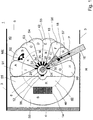
- Fig. 1 shows in plan view a manufacturing cell 1, with lateral limiting devices 3 and a rear limiting device 4.
- the rear limiting device 4 may be a fence, the lateral limiting devices 3 may be, for example, simple colored lines on the factory floor, or light barriers. From the front 6, the manufacturing cell is accessible and accessible.
- an industrial robot 8 with an attached to the robot hand 10 assembly tool.
- This can be, for example, a welding tongs or a drill or another robot-suitable tool known per se.
- the accessible interior of the manufacturing cell forms the working space 40 of the robot 8.
- the robot 8 is rotatably mounted on a base 12 about a vertical axis of rotation.
- the base 12 may be fixedly connected to the bottom of the manufacturing cell 1. It can also be a portable robot; then the base is slidable and the robot can be moved to different positions within the manufacturing cell 1 or even to positions outside the manufacturing cell 1.
- a danger area 48 delimited by a danger area boundary line 46. Is a person located within the danger area 46, he is within range of the robot arm and he is in great danger of colliding with the robotic arm in the course of its movements on its programmed trajectory.
- a security area 44 which adjoins the danger area to the outside is characterized by the fact that a person ME may possibly move quickly and unexpectedly out of this security area into the danger area and then collide there with the robot arm.
- a security area boundary 42 separates the security area from the work area surrounding it. In the work area 40, the stay of a person is not critical, there is no danger here.
- the robot 8 processes with its tool 10 workpieces 18 which are fed to it on a workpiece feed device 16, here for example a conveyor belt, from outside the production cell while traversing the working and safety area and are also removed again after processing.
- a workpiece feed device 16 here for example a conveyor belt
- each of these ultrasonic proximity sensors has sensor electronics, see FIGS. 20a, 22a, 24a, 26a, 28a, 30a, 32a, 34a in FIG Fig. 3 by means of which the presence of an object within the detection area assigned to the sensor can be detected and its distance to the sensor can be determined.
- the sensor electronics generates an output signal standardized according to any industry standard (eg 0-10V, 4-20mA) containing the two information just mentioned (namely a binary information "object or not “and analogue information” distance of the object from the sensor. "The sensor signal is transmitted to a safety controller via a sensor bus to which the proximity sensors are connected, see Fig. 3 ,
- Fig. 3 shows a block diagram of the function blocks, next to the in Fig. 1 shown? be needed to operate a device according to the invention in a method according to the invention.
- the sensor electronics continue to be designed so that they can dazzle certain definable distance ranges. That is, if an object is in such a kind previously determined Ausblend Scheme, so the sensor electronics no corresponding signal through the sensor bus via the safety controller passed.
- a scanner 36 is further attached to the rearward limiting device 4.
- This laser scanner 36 monitors the rear part of the working space 40 of the robot 8, which lies between the robot 8 and the rear limiting device 4.
- the detection area of the laser scanner 36 is approximately a semicircular area of the new one. ?
- the laser scanner 36 is a location and time-resolved sensor.
- the detection ranges of the proximity sensors 20, 22, 24, 26, 28, 30, 32, 34 and the laser scanner 36 are selected so that the outer boundary lines of the club-like sectors S1, S2, S3, S4, S5, S6, S7, S8 and the semicircular boundary of the detection area S9 of the laser scanner 36 taken together cover approximately the safety area boundary line 42.
- the hazardous area boundary line 46 divides each sector of an ultrasonic proximity sensor into two zones.
- the sector S1 of the ultrasonic proximity sensor 20 is divided into an outer safety zone A and an inner danger zone I. The same applies to the other sensors.
- the sector S2 of the sensor 22 is thus divided into the outer safety zone B and the inner danger zone K, the sector S3 of the sensor 24 into the outer safety zone C and the inner danger zone L, the sector S4 of the sensor 26 in the outer safety zone D and the inner danger zone M, the sector S5 of the sensor 28 in the outer safety zone E and the inner danger zone N, the sector S6 of the sensor 30 in the outer Safety zone F and the inner danger zone O, the sector S7 of the sensor 32 in the outer safety zone G and the inner danger zone P, and the sector S8 of the sensor 34 in the outer safety zone H and the inner danger zone Q.
- the position of the robot arm with the tool 10 relative to the respective hazard zone I, K, L, M, N, O, P, Q, is the safety control of position sensors, which are mounted on the robot arm or other robot axes transmitted.
- FIGS. 1 and Fig. 3 The inventive method will now be by combining the FIGS. 1 and Fig. 3 explained.
- the in Fig. 1 As shown, there is a human ME in zone B, which is the outer security zone associated with sector S2 of sensor 22.
- the tool 10 of the robot 8 is located in the zone P, which is the danger zone associated with the sector S 7 of the sensor 32.
- the safety controller receives from the robot control position information about the position of the tool 10 and from the sensor electronics assemblies 20 a to 34 a information whether in the ultrasonic proximity sensors associated zones are each objects or not, and at what distance they are. From the signals transmitted by the sensor electronics 22 a of the proximity sensor 22, the safety controller recognizes that an object is located in the safety area B.
- the safety controller receives the information that the tool 10 of the robot arm of the robot 8 is located in the zone P. Due to the programming, the safety controller knows that zones B and zone P are sufficiently far apart so that even if the object detected in zone B were human, there is no danger for it at this time with the robot arm and tool 10 collide. The safety control will do nothing, the robot 8 continues to operate normally.
- the sensor 32 reports via its sensor electronics 32 a of the safety controller that in the zone P, so its associated danger zone, also an object is, namely the workpiece 18 that the robot on the workpiece feed 16 is supplied for processing.
- the safety controller has programmed the information that detected objects in the zones P and G are workpieces which are fed via the conveyor belt 16 for processing. Therefore, the safety controller will do nothing if an object is detected in zone P.
- the zone P is geometrically designed so that there is no room for a person next to the conveyor belt 16 and the workpiece 18, so that it can not happen that a person is in zone P and endangered by the robot arm.
- the safety controller would cause the robot to enter a slowed-down safety mode to eliminate human hazard, should it break out of the Zone F should surprisingly move to Zone O where it would be in acute danger.
- the sensor 22 will transmit to the safety controller the information that an object is located in its danger zone K. Since this object could be human according to the program entered into the safety control, but zone K is still far enough away from the zone P in which the robot arm is currently located, will the safety control merely cause that? enters a slowed-down security mode to exclude a threat to a person in Zone K. If the person from the zone K approached the robot arm and the tool 10, ie, to move over the zones L, M and N to zone O, the safety controller would stop the robot at the latest when an object in zone N was detected bring.
- the proximity sensors 20, 22, 24, 26, 28, 30, 32, 34 were in the device according to Fig. 1 and Fig. 3 described as ultrasonic sensors. But it could also be just microwave sensors, or it could be a combination of microwaves and ultrasonic sensors.
- the rear space between the robot and the rear limiting device 4 is covered over the entire area by the laser scanner 36, as already mentioned above. Since the laser scanner 36 is spatially and temporally resolved, in him over a fairly complicated signal processing, which works much like an image processing algorithm, calculated in the entire area position of objects detected there and transmitted to the security control this information.
- the advantage of the laser scanner is that you only need one device to completely cover a relatively large area. However, this involves the disadvantage of the considerably larger costs for the laser scanner and the much greater complexity of the required sensor evaluation algorithms and electronics. Equally well could the rear space in the device according to Fig. 1 be covered by another eight backward oriented proximity sensors. In the Fig.
- Fig. 3 is in addition to the already discussed safety control the robot with the robot control and the interaction between safety control via the arrow labeled with action with the robot control, as well as the message of the robot arm position from the position sensors, in Fig. 3 indicated by the position-indicated arrow between the robot controller and the safety controller, furthermore a PC is shown, which is in communication with the safety controller, and furthermore a monitor connected to the PC for displaying and displaying the current safety situation in the manufacturing cell, and a configuration tool called Configuration.
- the configuration tool serves to configure the safety controller via the PC, that is to say to program and to transmit parameters such as detection threshold, sensitivity, local resolution of the sensors, detection threshold, etc., to the safety controller.
- the safety device whose physical construction is in Fig.
- Fig. 3 1 and their logically systematic structure in Fig. 3 shown is extremely flexible and adaptable to changing environmental conditions. This is particularly advantageous when the robot 8 would be used at a new work place. Because together with the robot 8 and its base 12 would yes, the safety sensors 20, 22, 24, 26, 28, 30, 32, 34, 36 moved with. At the new work site then only an adapted configuration of the safety control would be necessary, and the robot could continue to work after a short time with undiminished certainty. In conventional systems, however, the mechanical safety fence would have to be recreated and adjusted, or a surveillance camera in the space outside the robot would have to be reinstalled and adjusted, which is considerably more complicated.
- the device according to the invention and the method are also suitable for applications in which process light, such as, for example, UV radiation produced by welding, and usually a protective wall is required. Experience has shown that even such protection walls can be omitted.
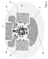
- Fig. 2 Finally, in schematic form, the geometric shape of the safety zones and hazard zones does not follow the circular or circular segment shape Fig. 1 is limited. Same elements and components in the Fig. 1 and 2 are denoted by the same reference numerals, in Fig. 2 supplemented by an apostrophe.
- the security area 44 - around the robot 8 - is designed like an ellipse.
- the robot 8 - carries again eight proximity sensors, optionally designed as an ultrasonic or microwave sensor, and designated 20-, 22-, 24-, 26-, 28-, 30-, 32-, 34-. These proximity sensors are each again associated with a sensor evaluation electronics which, according to the Fig. 3 interacts with the safety controller via a sensor bus.
- the Detection ranges of the safety sensors 20 -, 22 -, 24 -, 26 -, 28 -, 30 -, 32 -, 34 - are now set via their sensor electronics and the safety control so that the in Fig. 2 shown danger zones 48 - which are quite irregular in shape and essentially between the robot 8 and the conveyors 16 - or the tool station 14 - extend, are detected and covered.
- a device according to the invention is able to reliably cover even such irregular danger zones in a simple and cost-effective manner by hiding corresponding detection zones by the sensor electronics.
Landscapes
- Engineering & Computer Science (AREA)
- General Engineering & Computer Science (AREA)
- Mechanical Engineering (AREA)
- Radar, Positioning & Navigation (AREA)
- Remote Sensing (AREA)
- Robotics (AREA)
- Manipulator (AREA)
Claims (22)
- Dispositif de sécurité pour un robot industriel avec des parties mobiles, avec des capteurs de sécurité pour la détection d'objets dans l'espace de travail du robot industriel, avec une commande de sécurité, qui coopère avec une commande de manipulation et qui commande en l'occurrence des fonctions de l'appareil de manipulation importante pour la sécurité en fonction de signaux des capteurs de sécurité, dans lequel les capteurs de sécurité comprennent des capteurs d'approche sans contact, de telle manière qu'une partie importante pour la sécurité de l'espace de travail du robot industriel soit détectée par les plages de détection des capteurs d'approche et dans lequel les capteurs d'approche sont disposés à la base du robot industriel, caractérisé en ce que la partie importante pour la sécurité de l'espace de travail est divisée en secteurs, dans lequel un capteur d'approche sans contact ou un capteur à résolution spatiale et temporelle est associé à chaque secteur en tant que capteur de surveillance de secteur, et la plage de détection correspond au secteur qui lui est associé et en ce que chaque secteur associé à un capteur d'approche est divisé en au moins deux zones d'importance différente pour la sécurité, dans lequel l'importance pour la sécurité correspond à la distance des parties mobiles.
- Dispositif selon la revendication 1, caractérisé en ce que les capteurs de sécurité comprennent une combinaison de capteurs à résolution spatiale et temporelle et de capteurs d'approche sans contact.
- Dispositif selon la revendication 2, caractérisé en ce que les capteurs de sécurité comprennent une combinaison de capteurs à résolution spatiale et temporelle, de capteurs d'approche sans contact et d'interrupteurs de fin de course mécaniques ou de tapis de contact.
- Dispositif selon l'une quelconque des revendications précédentes, caractérisé en ce que les capteurs d'approche (20, 22, 24, 26, 28, 30, 32, 34, 36) présentent une combinaison de capteurs ayant des principes actifs physiques différents, en particulier des capteurs avec formation d'image, des capteurs à microondes et/ou radar.
- Dispositif selon l'une quelconque des revendications précédentes, caractérisé en ce que les capteurs d'approche transmettent à la commande de sécurité des informations au sujet de la présence d'un objet dans leur plage de détection respective et de la distance de l'objet par rapport au capteur respectif.
- Dispositif selon la revendication 5, caractérisé en ce que les capteurs d'approche suppriment des informations au sujet de la présence d'un objet se trouvant dans leur plage de détection lors de la transmission à la commande de sécurité, lorsque l'objet se trouve dans une plage de distance autorisée déterminée du capteur d'approche.
- Dispositif selon l'une quelconque des revendications 1 à 4, caractérisé en ce que les capteurs d'approche sont des interrupteurs d'approche avec des distances de coupure réglables de façon variable, de telle manière qu'ils transmettent à la commande de sécurité des informations au sujet de la présence d'un objet dans leur plage de surveillance respective et à une distance du capteur d'approche correspondant à la distance de coupure respectivement réglée.
- Dispositif selon la revendication 9, caractérisé en ce que chaque secteur associé à un capteur d'approche est divisé en une zone de travail, une zone de sécurité et une zone de danger, de telle manière qu'en cas de présence d'une personne dans la zone de danger le robot industriel soit arrêté, et qu'en cas de présence d'une personne dans la zone de sécurité du robot industriel il passe à un mode de fonctionnement de sécurité ralenti.
- Dispositif selon l'une quelconque des revendications précédentes, caractérisé en ce que les capteurs d'approche comprennent des capteurs à ultrasons.
- Dispositif selon l'une quelconque des revendications précédentes, caractérisé en ce que les capteurs d'approche comprennent des capteurs à microondes.
- Dispositif selon la revendication 10, caractérisé en ce que les capteurs de sécurité sont installés sur la base du robot industriel, de telle manière que l'espace de travail du robot industriel soit surveillé de l'intérieur vers l'extérieur à partir de la base.
- Dispositif selon la revendication 10, caractérisé en ce que des informations au sujet de la position du bras de robot industriel sont détectées par des capteurs de position sur le robot industriel, en particulier sur les axes du robot industriel, et sont transmises à la commande de sécurité.
- Procédé de sécurité d'un robot industriel avec des parties mobiles, dans lequel on utilise des capteurs de sécurité pour la détection d'objets dans l'espace de travail du robot industriel, de telle manière qu'une commande de sécurité coopère avec la commande du robot industriel et que des fonctions du robot industriel importantes pour la sécurité soient commandées par la commande de sécurité en fonction de signaux des capteurs de sécurité, dans lequel on détermine par zones des informations au sujet de la présence de personnes et/ou d'objets dans l'espace de travail du robot industriel au moyen de la technique de sécurité et on les transmet au moyen de la commande de sécurité, dans lequel on transmet par zones des informations au sujet de la position des parties mobiles du robot industriel par le robot industriel à la commande de sécurité et dans lequel on commande au moyen de la commande de sécurité en coopération avec la commande de robot industriel en fonction des deux informations des fonctions du robot industriel importantes pour la sécurité par zones, caractérisé en ce que l'espace de travail du robot industriel est divisé en secteurs et chaque secteur est en outre divisé en au moins deux zones d'importance différente pour la sécurité en correspondance avec la distance du bras de robot mobile, et en ce que l'on détecte des informations au sujet de la position du bras de robot industriel au moyen de capteurs de position sur les axes du robot industriel et on les transmet à la commande de sécurité.
- Procédé selon la revendication 13, caractérisé en ce que chaque secteur est divisé en une zone de travail, une zone de sécurité et une zone de danger et en ce qu'en cas de détection par les capteurs de sécurité de la présence d'une personne dans la zone de danger on arrête le robot industriel et en cas de présence d'une personne dans la zone de sécurité on commande le robot industriel dans un mode de fonctionnement de sécurité ralenti au moyen de la commande du robot industriel.
- Procédé selon la revendication 14, caractérisé en ce qu'en cas de détection par les capteurs de sécurité de la présence d'une personne dans une zone de sécurité et de détection simultanée par les capteurs de position de la position du bras de robot industriel dans la même zone de sécurité ou dans une zone de sécurité voisine, on commande le robot industriel dans un mode de fonctionnement de sécurité ralenti par la commande du robot.
- Procédé selon l'une quelconque des revendications 13 à 15, caractérisé en ce que des informations transmises par les capteurs de sécurité à la commande de sécurité au sujet d'objets en provenance d'une zone de sécurité ou de danger, dans laquelle le bras de robot industriel se trouve, sont masquées par la commande de sécurité.
- Procédé selon l'une quelconque des revendications 13 à 16, caractérisé en ce que des informations transmises par les capteurs de sécurité à la commande de sécurité au sujet d'objets en provenance d'une zone de sécurité ou de danger, dans laquelle se trouvent des pièces à manipuler par le robot industriel ou des dispositifs d'amenée pour ces pièces, sont masquées par la commande de sécurité.
- Procédé selon l'une quelconque des revendications 13 à 17, caractérisé en ce que l'on utilise des capteurs de sécurité selon l'une quelconque des revendications 1 à 12.
- Dispositif selon la revendication 9, caractérisé en ce que les capteurs à ultrasons présentent un angle d'ouverture compris entre 10° et 40°, en particulier avantageusement entre 12° et 30°, de telle manière que la partie de l'espace de travail du robot industriel surveillée par les capteurs à ultrasons soit divisée en secteurs avec des angles d'ouverture compris entre 10° et 40°, en particulier avantageusement entre 12° et 30°.
- Dispositif selon la revendication 10, caractérisé en ce que les capteurs à microondes travaillent selon le procédé OCMF (OCMF - onde continue modulée en fréquence).
- Dispositif selon la revendication 20, caractérisé en ce que les capteurs à microondes sont montés de façon mécaniquement pivotante et l'angle de pivotement peut être détecté avec un capteur d'angle, de telle manière qu'en plus de l'information au sujet de la distance de l'objet on obtienne encore une information au sujet de la direction dans laquelle l'objet se trouve.
- Dispositif selon la revendication 20, caractérisé en ce que des éléments individuels d'un réseau d'antennes des capteurs à microondes peuvent être commandés par un réseau à déphasage variable, de telle manière que la direction de rayonnement principale (lobe principal) des antennes à microondes puisse pivoter au moyen du changement des phases et que l'on obtienne ainsi, en plus des informations au sujet de la distance de l'objet, encore une information au sujet de la direction dans laquelle l'objet se trouve.
Applications Claiming Priority (2)
| Application Number | Priority Date | Filing Date | Title |
|---|---|---|---|
| DE102004041821A DE102004041821A1 (de) | 2004-08-27 | 2004-08-27 | Vorrichtung und Verfahren zur Sicherung eines maschinell gesteuerten Handhabungsgerätes |
| PCT/EP2005/009098 WO2006024431A1 (fr) | 2004-08-27 | 2005-08-23 | Dispositif et procede de securite pour un manipulateur a commande mecanique |
Publications (3)
| Publication Number | Publication Date |
|---|---|
| EP1781981A1 EP1781981A1 (fr) | 2007-05-09 |
| EP1781981B1 true EP1781981B1 (fr) | 2018-07-18 |
| EP1781981B2 EP1781981B2 (fr) | 2022-03-23 |
Family
ID=35447864
Family Applications (1)
| Application Number | Title | Priority Date | Filing Date |
|---|---|---|---|
| EP05787611.2A Expired - Lifetime EP1781981B2 (fr) | 2004-08-27 | 2005-08-23 | Dispositif et procede de securite pour un robot industriel |
Country Status (5)
| Country | Link |
|---|---|
| US (1) | US7783386B2 (fr) |
| EP (1) | EP1781981B2 (fr) |
| CN (1) | CN100549491C (fr) |
| DE (1) | DE102004041821A1 (fr) |
| WO (1) | WO2006024431A1 (fr) |
Cited By (1)
| Publication number | Priority date | Publication date | Assignee | Title |
|---|---|---|---|---|
| DE102020201151A1 (de) | 2020-01-30 | 2021-08-05 | Bhs Intralogistics Gmbh | Übergabeanordnung |
Families Citing this family (126)
| Publication number | Priority date | Publication date | Assignee | Title |
|---|---|---|---|---|
| DE10355876A1 (de) * | 2003-11-25 | 2005-07-28 | Hauni Maschinenbau Ag | Anordnung zum Befüllen und/oder Entleeren von mit Artikeln gefüllten und/oder zu befüllenden Behältern sowie Handhabungsvorrichtung zum Transportieren der Behälter |
| FR2894318B1 (fr) | 2005-12-07 | 2008-03-07 | Lectra Sa | Procede de gestion de securite active pour une machine de travail automatique. |
| US8676379B2 (en) * | 2006-07-04 | 2014-03-18 | Panasonic Corporation | Device and method for controlling robot arm, robot, and robot arm control program |
| DE102006046759B4 (de) * | 2006-09-29 | 2018-05-17 | Abb Ag | Verfahren zur Erhöhung der Sicherheit beim Betrieb eines Roboters |
| DE102006052017B4 (de) | 2006-11-03 | 2009-03-05 | Homag Holzbearbeitungssysteme Ag | Bearbeitungsmaschine |
| DE102007006708A1 (de) | 2007-02-10 | 2008-08-14 | Abb Research Ltd. | Verfahren zur Sicherung eines Handhabungsgeräts |
| DE102007013299A1 (de) * | 2007-03-06 | 2008-09-11 | Cedes Ag | Sensorvorrichtung sowie Anlage mit einem Förderer und einer Sensorvorrichtung |
| JP4512200B2 (ja) * | 2007-03-15 | 2010-07-28 | 株式会社日立製作所 | ロボット |
| DE102007014612A1 (de) | 2007-03-23 | 2008-09-25 | TRüTZSCHLER GMBH & CO. KG | Vorrichtung zur Überwachung und Sicherung von Gefahrenbereichen an kraftgetriebenen Textilmaschinen, insbesondere Spinnereivorbereitungsmaschinen |
| DE102007018810A1 (de) | 2007-04-20 | 2008-10-30 | Siemens Ag | Verfahren zur Bewegungsüberwachung bei einer medizintechnischen Anlage sowie zugehörige medizintechnische Anlage |
| DE102007020448B4 (de) | 2007-04-27 | 2015-10-15 | Trützschler GmbH & Co Kommanditgesellschaft | Vorrichtung an einer Spinnereivorbereitungsmaschine, z.B. Strecke, Karde, Kämmmaschine o. dgl. mit einem Streckwerk |
| DE102007028390A1 (de) * | 2007-06-15 | 2008-12-18 | Abb Research Ltd. | Prozesssteuerung, System und Verfahren zur automatisierten Anpassung von Prozessparametern wenigstens einer Handhabungsvorrichtung |
| DE102007032533B4 (de) * | 2007-07-12 | 2015-07-02 | Siemens Aktiengesellschaft | Verfahren zum Betreiben eines Medizinischen Diagnose- und/oder Therapiegeräts und Medizinisches Diagnose- und/oder Therapiegerät |
| DE102007034981A1 (de) * | 2007-07-26 | 2008-08-28 | Siemens Ag | Verfahren zum Steuern der Bewegungen eines beweglichen Teils eines medizinischen Diagnose- und/oder Interventionssystems |
| DE102007042954A1 (de) * | 2007-08-30 | 2009-03-05 | Balluff Gmbh | Mikrowellen-Näherungssensor und Verfahren zur Ermittlung des Abstands zwischen einem Messkopf und einem Zielobjekt |
| US8549966B2 (en) * | 2007-10-22 | 2013-10-08 | Formax, Inc. | Output conveyor for a food article slicing machine |
| JP5088156B2 (ja) * | 2008-02-05 | 2012-12-05 | 株式会社ジェイテクト | ロボット安全監視装置 |
| US7810697B2 (en) * | 2008-08-22 | 2010-10-12 | Honda Motor Co., Ltd. | Turntable welding system with light curtain protection |
| DE102008041602B4 (de) * | 2008-08-27 | 2015-07-30 | Deutsches Zentrum für Luft- und Raumfahrt e.V. | Roboter und Verfahren zum Steuern eines Roboters |
| DE102008041845B4 (de) * | 2008-09-05 | 2012-03-22 | Koenig & Bauer Aktiengesellschaft | Druckeinheit einer Druckmaschine mit mindestens zwei relativ zueinander positionsveränderbaren Gestellteilen |
| ITTR20080005A1 (it) * | 2008-11-06 | 2010-05-07 | Dies Srl | Sicurezza contro gli infortuni derivati dallb,"utilizzo di utensili da taglio |
| JP4648486B2 (ja) * | 2009-01-26 | 2011-03-09 | ファナック株式会社 | 人間とロボットとの協調動作領域を有する生産システム |
| DE202009006683U1 (de) * | 2009-05-08 | 2010-09-30 | Sick Ag | Zugangsabsicherungssystem |
| US8949480B2 (en) * | 2009-05-11 | 2015-02-03 | GM Global Technology Operations LLC | Method and system for testing safety automation logic of a manufacturing cell |
| DE102009038721A1 (de) * | 2009-08-25 | 2011-03-03 | Kuka Roboter Gmbh | Anordnung und Verfahren zur sicheren Steuerung eines Manipulators |
| DE102009040145A1 (de) * | 2009-09-04 | 2011-03-10 | Kuka Roboter Gmbh | Verfahren und Vorrichtung zum Stillsetzen eines Manipulators |
| EP2353799B8 (fr) | 2010-02-05 | 2018-08-08 | KUKA Deutschland GmbH | Procédé et dispositif de surveillance d'une chambre de manipulateur |
| DE102010007025A1 (de) | 2010-02-05 | 2011-08-11 | KUKA Laboratories GmbH, 86165 | Verfahren und Vorrichtung zur Überwachung eines Manipulatorraumes |
| DE102010007027A1 (de) | 2010-02-05 | 2011-08-11 | KUKA Laboratories GmbH, 86165 | Verfahren und Vorrichtung zur Überwachung eines Manipulatorraumes |
| US9230419B2 (en) | 2010-07-27 | 2016-01-05 | Rite-Hite Holding Corporation | Methods and apparatus to detect and warn proximate entities of interest |
| DE102010047641B4 (de) * | 2010-10-06 | 2022-06-15 | Kuka Roboter Gmbh | Steuerung eines Roboters |
| DE102010063214A1 (de) * | 2010-12-16 | 2012-06-21 | Robert Bosch Gmbh | Sicherungseinrichtung für eine Handhabungsvorrichtung, insbesondere einen Industrieroboter, sowie Verfahren zum Betreiben der Sicherungseinrichtung |
| JP2012236244A (ja) * | 2011-05-10 | 2012-12-06 | Sony Corp | ロボット装置、ロボット装置の制御方法、並びにロボット装置制御用プログラム |
| FR2987774B1 (fr) * | 2012-03-12 | 2015-02-27 | Sidel Participations | Installation robotisee automatique |
| US20130245823A1 (en) * | 2012-03-19 | 2013-09-19 | Kabushiki Kaisha Yaskawa Denki | Robot system, robot hand, and robot system operating method |
| JP5924134B2 (ja) * | 2012-05-30 | 2016-05-25 | セイコーエプソン株式会社 | 侵入検出装置,ロボットシステム,侵入検出方法および侵入検出プログラム |
| US9120233B2 (en) * | 2012-05-31 | 2015-09-01 | Toyota Motor Engineering & Manufacturing North America, Inc. | Non-contact optical distance and tactile sensing system and method |
| DE102012011108A1 (de) | 2012-06-05 | 2013-12-19 | Kuka Roboter Gmbh | Verfahren und Vorrichtung zum Steuern einer Manipulatoranordnung |
| JP5768828B2 (ja) * | 2013-03-15 | 2015-08-26 | 株式会社安川電機 | ロボットシステム、及び、ロボットシステムの制御方法 |
| JP5846145B2 (ja) * | 2013-03-18 | 2016-01-20 | 株式会社安川電機 | ロボットシステム、及び、ロボットシステムの制御方法 |
| JP5672327B2 (ja) * | 2013-03-19 | 2015-02-18 | 株式会社安川電機 | ロボットシステム |
| DE102013104265A1 (de) * | 2013-04-26 | 2014-10-30 | Pilz Gmbh & Co. Kg | Vorrichtung und Verfahren zum Absichern einer automatisiert arbeitenden Maschine |
| EP2824522B1 (fr) * | 2013-05-06 | 2017-11-29 | ABB Schweiz AG | Fourniture de sécurité humaine dans des environnements d'automatisation mobile |
| JP5892132B2 (ja) * | 2013-09-13 | 2016-03-23 | 株式会社安川電機 | 制御装置及びロボットシステム |
| CN103577852B (zh) * | 2013-10-29 | 2017-02-01 | 电子科技大学 | 一种基于有源rfid的分级监控方法及系统 |
| TWI547355B (zh) * | 2013-11-11 | 2016-09-01 | 財團法人工業技術研究院 | 人機共生安全監控系統及其方法 |
| US10330258B2 (en) | 2013-12-24 | 2019-06-25 | Robert Bosch Tool Corporation | Power tool with ultrasonic sensor for sensing contact between an implement and an object |
| US9452531B2 (en) * | 2014-02-04 | 2016-09-27 | Microsoft Technology Licensing, Llc | Controlling a robot in the presence of a moving object |
| US10279470B2 (en) * | 2014-06-12 | 2019-05-07 | Play-i, Inc. | System and method for facilitating program sharing |
| EP3017920B1 (fr) * | 2014-11-07 | 2017-08-23 | Comau S.p.A. | Robot industriel et procédé pour commander un tel robot |
| DE102014226691A1 (de) * | 2014-12-19 | 2016-06-23 | Carl Zeiss Industrielle Messtechnik Gmbh | Verfahren zur Überwachung eines Koordinatenmessgeräts |
| DE102014226789A1 (de) * | 2014-12-22 | 2016-07-07 | Kuka Roboter Gmbh | Verfahren und Manipulatoranordnung zum bedingten Anhalten zumindest eines Manipulators auf einer Bahn |
| CN104723350B (zh) * | 2015-03-16 | 2016-07-20 | 珠海格力电器股份有限公司 | 工业机器人安全防护智能控制方法及系统 |
| US10834065B1 (en) | 2015-03-31 | 2020-11-10 | F5 Networks, Inc. | Methods for SSL protected NTLM re-authentication and devices thereof |
| CN105150189B (zh) * | 2015-06-19 | 2017-01-18 | 北京云迹科技有限公司 | 一种轮式机器人驱动模式的无缝切换方法 |
| JP6554945B2 (ja) * | 2015-07-03 | 2019-08-07 | 株式会社デンソーウェーブ | ロボットシステム |
| US10198706B2 (en) * | 2015-07-31 | 2019-02-05 | Locus Robotics Corp. | Operator identification and performance tracking |
| DE102015215234A1 (de) | 2015-08-10 | 2017-02-16 | Fraunhofer-Gesellschaft zur Förderung der angewandten Forschung e.V. | Einrichtung zum Absichern eines Sicherheitsbereichs um mindestens eine automatisch arbeitende Maschine |
| US10215852B1 (en) * | 2015-10-05 | 2019-02-26 | Google Llc | Robotic radar assistance |
| US10404698B1 (en) | 2016-01-15 | 2019-09-03 | F5 Networks, Inc. | Methods for adaptive organization of web application access points in webtops and devices thereof |
| GB2548154A (en) * | 2016-03-11 | 2017-09-13 | Sony Computer Entertainment Europe Ltd | Virtual reality |
| JP6733239B2 (ja) * | 2016-03-18 | 2020-07-29 | セイコーエプソン株式会社 | 制御装置及びロボットシステム |
| EP3243609A1 (fr) * | 2016-05-09 | 2017-11-15 | OpiFlex Automation AB | Système de robot industriel sans barrière |
| CN107378941B (zh) * | 2016-05-16 | 2022-02-18 | 精工爱普生株式会社 | 机器人、控制装置以及机器人系统 |
| US11045955B2 (en) * | 2016-05-26 | 2021-06-29 | Mitsubishi Electric Corporation | Robot control device |
| EP3252364B1 (fr) * | 2016-05-31 | 2019-03-27 | Inxpect S.p.A. | Appareil radar pour la formation d'une barrière linéaire de protection et système rélatif |
| DE102016007520A1 (de) * | 2016-06-20 | 2017-12-21 | Kuka Roboter Gmbh | Überwachung einer Roboteranordnung |
| DE102016114835A1 (de) * | 2016-08-10 | 2018-02-15 | Joanneum Research Forschungsgesellschaft Mbh | Robotervorrichtung |
| CN107717982B (zh) * | 2016-08-12 | 2020-09-25 | 财团法人工业技术研究院 | 机械手臂的控制装置及操作方法 |
| US20180052512A1 (en) * | 2016-08-16 | 2018-02-22 | Thomas J. Overly | Behavioral rehearsal system and supporting software |
| US11000953B2 (en) * | 2016-08-17 | 2021-05-11 | Locus Robotics Corp. | Robot gamification for improvement of operator performance |
| JP6822069B2 (ja) * | 2016-11-01 | 2021-01-27 | オムロン株式会社 | 監視システム、監視装置、および監視方法 |
| DE102016222245A1 (de) | 2016-11-14 | 2018-05-30 | Volkswagen Aktiengesellschaft | Einrichtung und Verfahren zur Einwirkung auf Gegenstände |
| US12103170B2 (en) | 2017-01-13 | 2024-10-01 | Clara Vu | Dynamic, interactive signaling of safety-related conditions in a monitored environment |
| US11518051B2 (en) | 2017-02-07 | 2022-12-06 | Veo Robotics, Inc. | Dynamic, interactive signaling of safety-related conditions in a monitored environment |
| DE102017100780A1 (de) | 2017-01-17 | 2018-07-19 | Abb Schweiz Ag | Verfahren zur Reduzierung von Messstörungen beim Betrieb eines kollaborierenden Industrieroboters mit einer radarbasierten Kollisionserkennung sowie Industrieroboter zur Durchführung des Verfahrens |
| CN110494900A (zh) | 2017-02-07 | 2019-11-22 | 韦奥机器人股份有限公司 | 工作空间安全监控和设备控制 |
| US11541543B2 (en) | 2017-02-07 | 2023-01-03 | Veo Robotics, Inc. | Dynamic, interactive signaling of safety-related conditions in a monitored environment |
| US11820025B2 (en) | 2017-02-07 | 2023-11-21 | Veo Robotics, Inc. | Safe motion planning for machinery operation |
| DE102017202004A1 (de) | 2017-02-08 | 2018-08-09 | Thyssenkrupp Ag | Vorrichtung zur Absicherung eines maschinell gesteuerten Handhabungsgeräts und Verfahren |
| US10766140B2 (en) * | 2017-04-13 | 2020-09-08 | Battelle Memorial Institute | Teach mode collision avoidance system and method for industrial robotic manipulators |
| CN110998471A (zh) * | 2017-05-09 | 2020-04-10 | 云海智行股份有限公司 | 机器人运动控制系统及方法 |
| DE102017111367A1 (de) | 2017-05-24 | 2018-11-29 | Abb Schweiz Ag | Abstandsmesssystem, -verfahren und diese verwendendes Robotersystem |
| DE102017005604A1 (de) * | 2017-06-12 | 2018-12-13 | Kuka Deutschland Gmbh | Überwachung eines Roboters |
| EP3421190B1 (fr) * | 2017-06-28 | 2022-05-04 | ABB Schweiz AG | Appareillage de commutation à fonctionnement et maintenance sans personnel et procédé de fonctionnement associé |
| EP3421189B1 (fr) * | 2017-06-28 | 2019-05-22 | Sick AG | Procédé de surveillance d'une machine |
| EP3437804A1 (fr) * | 2017-08-02 | 2019-02-06 | ABB Schweiz AG | Procédé de commande de robot |
| JP6633580B2 (ja) * | 2017-08-02 | 2020-01-22 | ファナック株式会社 | ロボットシステム及びロボット制御装置 |
| US11072071B2 (en) * | 2017-09-19 | 2021-07-27 | Autodesk, Inc. | Modifying robot dynamics in response to human presence |
| JP2019058990A (ja) * | 2017-09-27 | 2019-04-18 | ファナック株式会社 | ロボットシステム |
| DE102017123295A1 (de) * | 2017-10-06 | 2019-04-11 | Pilz Gmbh & Co. Kg | Sicherheitssystem zur Absicherung eines kooperativen Betriebs von Menschen, Robotern und Maschinen |
| DE102017218917A1 (de) * | 2017-10-24 | 2019-04-25 | Robert Bosch Gmbh | Überwachungsvorrichtung, Industrieanlage, Verfahren zur Überwachung sowie Computerprogramm |
| US12097625B2 (en) | 2018-02-06 | 2024-09-24 | Veo Robotics, Inc. | Robot end-effector sensing and identification |
| US12049014B2 (en) | 2018-02-06 | 2024-07-30 | Veo Robotics, Inc. | Workplace monitoring and semantic entity identification for safe machine operation |
| IT201800002494A1 (it) | 2018-02-08 | 2019-08-08 | Omron Europe B V | Dispositivo di monitoraggio per monitorare un settore limite di una zona di sicurezza. |
| IT201800005091A1 (it) | 2018-05-04 | 2019-11-04 | "Procedimento per monitorare lo stato di funzionamento di una stazione di lavorazione, relativo sistema di monitoraggio e prodotto informatico" | |
| DE102018110852A1 (de) | 2018-05-07 | 2019-11-07 | Kinotex Sensor Gmbh | Vorrichtung und Verfahren zur Sicherung eines maschinell oder automatisch gesteuerten beweglichen Gerätes und Sensorkachel |
| DE102018113359B4 (de) | 2018-06-05 | 2020-07-30 | Sick Ag | Sensorsystem mit optoelektronischen Distanzsensoren |
| EP3804924A4 (fr) * | 2018-06-11 | 2021-08-04 | Panasonic Intellectual Property Management Co., Ltd. | Système de mesure de distance et procédé de mesure de distance |
| DE102018114156B3 (de) * | 2018-06-13 | 2019-11-14 | Volkswagen Aktiengesellschaft | Verfahren zur Steuerung eines Roboters, insbesondere eines Industrieroboters, sowie Vorrichtung zur Steuerung des Roboters |
| JP7155660B2 (ja) * | 2018-06-26 | 2022-10-19 | セイコーエプソン株式会社 | ロボット制御装置およびロボットシステム |
| JP2020049642A (ja) * | 2018-09-28 | 2020-04-02 | セイコーエプソン株式会社 | 制御装置、ロボットシステム、及びロボット |
| DE102018126216A1 (de) * | 2018-09-28 | 2020-04-02 | Still Gmbh | Verfahren zur Absicherung eines Arbeitsbereichs eines mobilen Logistik-Roboters mittels adaptiver Schutzfelder |
| KR102228866B1 (ko) * | 2018-10-18 | 2021-03-17 | 엘지전자 주식회사 | 로봇 및 그의 제어 방법 |
| CN109397289A (zh) * | 2018-11-13 | 2019-03-01 | 华东师范大学 | 一种工业机器人的安全控制装置及控制方法 |
| JP6985242B2 (ja) * | 2018-11-30 | 2021-12-22 | ファナック株式会社 | ロボットの監視システムおよびロボットシステム |
| DE102018133472B3 (de) * | 2018-12-21 | 2020-03-12 | Franka Emika Gmbh | Bewegungsüberwachung eines Robotermanipulators |
| JP7260422B2 (ja) * | 2019-07-02 | 2023-04-18 | ファナック株式会社 | 異物検出装置 |
| DE202019105667U1 (de) | 2019-10-15 | 2021-01-19 | Otto Christ Ag | Kamerabasierte Absicherung für Fahrzeugbehandlungsanlagen |
| EP4069472A4 (fr) * | 2019-12-05 | 2024-03-20 | MAGNA Powertrain GmbH & Co KG | Procédé et configuration dans le cadre de la robotique sans barrière |
| IT201900025087A1 (it) * | 2019-12-20 | 2021-06-20 | Biesse Spa | Sistema di monitoraggio della sicurezza operativa di macchine utensili per lavorazioni industriali |
| IT202000019618A1 (it) * | 2020-08-07 | 2022-02-07 | Scm Group Spa | Macchina con sistema di sicurezza. |
| DE102020129233A1 (de) | 2020-11-05 | 2022-05-05 | Basf Se | Fahrzeug und Verfahren zur Vermeidung einer Kollision eines Fahrzeugs mit einem Hindernis |
| DE202020106363U1 (de) | 2020-11-05 | 2022-02-08 | Basf Se | Fahrzeug und Vorrichtung zur Durchführung eines Verfahrens zur Vermeidung einer Kollision eines Fahrzeugs mit einem Hindernis |
| DE102021100445A1 (de) | 2021-01-13 | 2022-07-14 | Basf Se | Fahrzeug mit Sicherheitssensorik und Sicherheitsverfahren |
| DE202021100125U1 (de) | 2021-01-13 | 2022-04-20 | Basf Se | Fahrzeug mit Sicherheitssensorik und Vorrichtung zur Durchführung eines Sicherheitsverfahrens |
| EP4070921A1 (fr) | 2021-04-08 | 2022-10-12 | Collobro AB | Système de sécurité pour un robot collaboratif |
| US12459123B2 (en) | 2022-02-16 | 2025-11-04 | Mantis Robotics, Inc. | Robot system with object detecting sensors |
| US12449546B2 (en) * | 2022-04-15 | 2025-10-21 | Zebra Technologies Corporation | Lidar sensor system for enabling or disabling use of a robotic arm |
| DE102022131773A1 (de) | 2022-11-30 | 2024-06-06 | Pilz Gmbh & Co. Kg | Sicherheitsvorrichtung zum Absichern eines Gefahrenbereichs einer automatisiert arbeitenden Maschine, insbesondere eines Roboters |
| DE102022131775A1 (de) | 2022-11-30 | 2024-06-06 | Pilz Gmbh & Co. Kg | Sicherheitsvorrichtung zum Absichern eines Gefahrenbereichs einer automatisiert arbeitenden Maschine, insbesondere eines Roboters |
| DE102022133248B4 (de) * | 2022-12-14 | 2025-01-23 | Sick Ag | System mit einem Sensor und Verfahren mit einem Sensor zur Überwachung mehrerer Schutzbereiche |
| CN115648226B (zh) * | 2022-12-27 | 2023-03-21 | 珞石(北京)科技有限公司 | 基于任务空间分割和动态距离监控的安全人机协作方法 |
| DE102023100604A1 (de) * | 2023-01-12 | 2024-07-18 | Khs Gmbh | Behälterbehandlungsanlage, Behälterbehandlungsmaschine und Verfahren zum Steuern einer Behälterbehandlungsanlage |
| WO2025111632A1 (fr) * | 2023-11-29 | 2025-06-05 | Agile Projects Pty Ltd | Système de sécurité |
| EP4729245A1 (fr) * | 2024-10-21 | 2026-04-22 | Sick Ag | Système, utilisation et procédé de commande sécurisée d'un robot industriel, en particulier d'une grue à conteneurs |
Citations (7)
| Publication number | Priority date | Publication date | Assignee | Title |
|---|---|---|---|---|
| US4804860A (en) | 1985-05-02 | 1989-02-14 | Robotic Vision Systems, Inc. | Robot cell safety system |
| US5165064A (en) | 1991-03-22 | 1992-11-17 | Cyberotics, Inc. | Mobile robot guidance and navigation system |
| DE19527832A1 (de) | 1995-07-29 | 1997-02-06 | Werner & Pfleiderer Lebensmitt | Vorrichtung zum Beschicken und Entleeren von Industriebacköfen und Verfahren zum Betrieb einer derartigen Vorrichtung |
| US5758298A (en) | 1994-03-16 | 1998-05-26 | Deutsche Forschungsanstalt Fur Luft-Und Raumfahrt E.V. | Autonomous navigation system for a mobile robot or manipulator |
| DE19903210A1 (de) | 1998-07-13 | 2000-01-20 | Mitsubishi Electric Corp | Hindernisdetektionsgerät |
| JP2002264070A (ja) | 2001-03-09 | 2002-09-18 | Denso Corp | 移動ロボット及び移動ロボットシステム |
| DE10152543A1 (de) | 2001-10-24 | 2003-05-08 | Sick Ag | Verfahren und Vorrichtung zum Steuern einer sicherheitsrelevanten Funktion einer Maschine |
Family Cites Families (31)
| Publication number | Priority date | Publication date | Assignee | Title |
|---|---|---|---|---|
| DE3010667C2 (de) * | 1980-03-20 | 1982-11-11 | Aeg-Elotherm Gmbh, 5630 Remscheid | Sicherheitseinrichtung für eine Werkzeugmaschine |
| JP2566550B2 (ja) | 1984-01-31 | 1996-12-25 | ファナック 株式会社 | ロボツト動作に対するオペレ−タ保護方法 |
| US4674057A (en) * | 1984-02-14 | 1987-06-16 | Lockheed Corporation | Ultrasonic ranging control system for industrial robots |
| US4829442A (en) * | 1986-05-16 | 1989-05-09 | Denning Mobile Robotics, Inc. | Beacon navigation system and method for guiding a vehicle |
| US4777416A (en) * | 1986-05-16 | 1988-10-11 | Denning Mobile Robotics, Inc. | Recharge docking system for mobile robot |
| US4772875A (en) * | 1986-05-16 | 1988-09-20 | Denning Mobile Robotics, Inc. | Intrusion detection system |
| US4736116A (en) * | 1986-05-16 | 1988-04-05 | Denning Mobile Robotics, Inc. | Power-up sequencing apparatus |
| US4751658A (en) * | 1986-05-16 | 1988-06-14 | Denning Mobile Robotics, Inc. | Obstacle avoidance system |
| US4710020A (en) * | 1986-05-16 | 1987-12-01 | Denning Mobil Robotics, Inc. | Beacon proximity detection system for a vehicle |
| CH682351A5 (fr) | 1986-10-16 | 1993-08-31 | Sohard Ag | |
| DE3700009A1 (de) | 1987-01-02 | 1988-07-14 | Mel Mikroelektronik Gmbh | Optoelektronische schutzzonenvorrichtung |
| EP0435816A1 (fr) * | 1989-12-21 | 1991-07-03 | Maschinenfabrik Rieter Ag | Ouvreuse de balles avec un appareil de sécurité commandé par un détecteur |
| DE4235161A1 (de) | 1991-11-25 | 1993-05-27 | Intecma Konstruktions Und Hand | Vorrichtung zum sichern eines begrenzten arbeitsbereich |
| US5280622A (en) * | 1992-07-17 | 1994-01-18 | Mitsubishi Semiconductor America, Inc. | Combined light beam and ultrasonic transducer safety sensing system |
| KR0152096B1 (ko) * | 1992-10-26 | 1998-10-15 | 윤종용 | 이동감시용 로보트의 장애물 감지장치 |
| US5495576A (en) * | 1993-01-11 | 1996-02-27 | Ritchey; Kurtis J. | Panoramic image based virtual reality/telepresence audio-visual system and method |
| DE9312840U1 (de) | 1993-04-27 | 1993-12-16 | ELAN Schaltelemente GmbH & Co. KG, 35435 Wettenberg | Schaltmatte |
| US5956465A (en) * | 1996-04-04 | 1999-09-21 | Nissan Motor Co., Ltd. | Production facility with automatic movable body for man-machine cooperation |
| US6055042A (en) * | 1997-12-16 | 2000-04-25 | Caterpillar Inc. | Method and apparatus for detecting obstacles using multiple sensors for range selective detection |
| JP2001282301A (ja) * | 2000-04-03 | 2001-10-12 | Matsushita Electric Ind Co Ltd | ロボットの制御装置 |
| US20060076048A1 (en) * | 2000-04-27 | 2006-04-13 | Russell Gaudiana | Photo-sensing photovoltaic with positioning facility |
| US6617845B1 (en) * | 2000-04-28 | 2003-09-09 | Rockwell Automation Technologies, Inc. | Proximity sensor resistant to environmental effects |
| US7768549B2 (en) | 2001-06-08 | 2010-08-03 | Honeywell International Inc. | Machine safety system with mutual exclusion zone |
| US6683432B2 (en) * | 2001-09-12 | 2004-01-27 | Eigenpoint Company | Safety circuit with automatic recovery |
| IL145680A0 (en) * | 2001-09-26 | 2002-06-30 | Friendly Robotics Ltd | Robotic vacuum cleaner |
| DE10162412A1 (de) | 2001-12-19 | 2003-07-10 | Kuka Roboter Gmbh | Einrichtung und Verfahren zum Sichern von Vorrichtungen mit frei im Raum beweglichen Teilen |
| JP2004154916A (ja) * | 2002-11-08 | 2004-06-03 | Fanuc Ltd | 自動機械システムの安全装置 |
| EP1460497B1 (fr) * | 2003-02-12 | 2012-11-14 | Omron Corporation | Commande de sécurité |
| GB2417090A (en) * | 2003-04-28 | 2006-02-15 | Stephen James Crampton | CMM arm with exoskeleton |
| DE10324628A1 (de) | 2003-05-28 | 2004-12-16 | Daimlerchrysler Ag | Steuerverfahren für einen Roboter |
| JP4212970B2 (ja) * | 2003-06-30 | 2009-01-21 | 株式会社キーエンス | 安全リレーシステム |
-
2004
- 2004-08-27 DE DE102004041821A patent/DE102004041821A1/de not_active Withdrawn
-
2005
- 2005-08-23 WO PCT/EP2005/009098 patent/WO2006024431A1/fr not_active Ceased
- 2005-08-23 EP EP05787611.2A patent/EP1781981B2/fr not_active Expired - Lifetime
- 2005-08-23 CN CNB2005800288361A patent/CN100549491C/zh not_active Expired - Lifetime
- 2005-08-23 US US11/661,290 patent/US7783386B2/en active Active
Patent Citations (7)
| Publication number | Priority date | Publication date | Assignee | Title |
|---|---|---|---|---|
| US4804860A (en) | 1985-05-02 | 1989-02-14 | Robotic Vision Systems, Inc. | Robot cell safety system |
| US5165064A (en) | 1991-03-22 | 1992-11-17 | Cyberotics, Inc. | Mobile robot guidance and navigation system |
| US5758298A (en) | 1994-03-16 | 1998-05-26 | Deutsche Forschungsanstalt Fur Luft-Und Raumfahrt E.V. | Autonomous navigation system for a mobile robot or manipulator |
| DE19527832A1 (de) | 1995-07-29 | 1997-02-06 | Werner & Pfleiderer Lebensmitt | Vorrichtung zum Beschicken und Entleeren von Industriebacköfen und Verfahren zum Betrieb einer derartigen Vorrichtung |
| DE19903210A1 (de) | 1998-07-13 | 2000-01-20 | Mitsubishi Electric Corp | Hindernisdetektionsgerät |
| JP2002264070A (ja) | 2001-03-09 | 2002-09-18 | Denso Corp | 移動ロボット及び移動ロボットシステム |
| DE10152543A1 (de) | 2001-10-24 | 2003-05-08 | Sick Ag | Verfahren und Vorrichtung zum Steuern einer sicherheitsrelevanten Funktion einer Maschine |
Non-Patent Citations (2)
| Title |
|---|
| ANONYMOUS: "Tastender Laser Scanner PLS", TECHNISCHE BESCHREIBUNG, 22 July 2004 (2004-07-22), pages 1 - 78, XP055582883 |
| ROSS: "OTS-Systeme in der Robotik, Roboter Ohne Trennende Schutzeinrichtun-gen", BKM BERICHTE, - 25 June 2002 (2002-06-25), XP055582528, ISBN: 3-8316-0901-2 |
Cited By (1)
| Publication number | Priority date | Publication date | Assignee | Title |
|---|---|---|---|---|
| DE102020201151A1 (de) | 2020-01-30 | 2021-08-05 | Bhs Intralogistics Gmbh | Übergabeanordnung |
Also Published As
| Publication number | Publication date |
|---|---|
| CN101018973A (zh) | 2007-08-15 |
| US20080021597A1 (en) | 2008-01-24 |
| WO2006024431A1 (fr) | 2006-03-09 |
| DE102004041821A1 (de) | 2006-03-16 |
| EP1781981A1 (fr) | 2007-05-09 |
| US7783386B2 (en) | 2010-08-24 |
| EP1781981B2 (fr) | 2022-03-23 |
| CN100549491C (zh) | 2009-10-14 |
Similar Documents
| Publication | Publication Date | Title |
|---|---|---|
| EP1781981B1 (fr) | Dispositif et procede de securite pour un robot industriel | |
| EP2989369B1 (fr) | Dispositif et procédé de sécurisation d'une machine travaillant de manière automatisée | |
| EP1635107B1 (fr) | Procédé et dispositif de commande d'une fonction de sécurité d'une machine | |
| EP1353196B1 (fr) | Détection d'un objet et barrière optique | |
| EP2402114B1 (fr) | Dispositif et procédé de protection de broche de travail | |
| EP2660012A2 (fr) | Dispositif de surveillance de positions d'un robot et installation de fabrication dotée d'un dispositif de surveillance | |
| DE102016222245A1 (de) | Einrichtung und Verfahren zur Einwirkung auf Gegenstände | |
| DE102019131774A1 (de) | Überwachungssystem für Roboter und Robotersystem | |
| EP3910230A1 (fr) | Dispositif de surveillance | |
| EP2114629B1 (fr) | Procédé de sécurisation d'un appareil de manipulation | |
| DE202008016093U1 (de) | Überwachungssensor | |
| EP3150898B1 (fr) | Procede de commande automatisee d'un composant de machine | |
| EP4151899A1 (fr) | Dispositif de surveillance | |
| WO2024115658A1 (fr) | Dispositif de sécurité pour sécuriser une zone de danger pour une machine de travail automatique, en particulier un robot | |
| EP3770708B1 (fr) | Dispositif de surveillance | |
| EP3640522A1 (fr) | Dispositif de surveillance | |
| WO2017182126A1 (fr) | Surveillance de l'espace de travail d'un robot quant à la pénétration d'objets | |
| WO2022179698A1 (fr) | Procédé pour déterminer une distance minimale entre un objet et une surface d'appareil, dispositif de sécurité pour un appareil de manutention ayant une surface d'appareil, et appareil de manutention | |
| EP4354010B1 (fr) | Dispositif de surveillance | |
| DE102023120220B4 (de) | Sicherheitssystem zur Absicherung eines Aktionsbereichs einer Produktionsanlage | |
| EP3757443B1 (fr) | Élément de surveillance et procédé de sécurisation de zones dangereuses | |
| WO2024115657A1 (fr) | Dispositif de sécurité pour sécuriser une zone dangereuse d'une machine fonctionnant de manière automatisée, en particulier un robot | |
| EP3770481B1 (fr) | Dispositif capteur et procédés de surveillance de zone dangereuse | |
| EP3869240B1 (fr) | Agencement de capteurs et procédé de fonctionnement d'un agencement de capteurs | |
| EP4047257A1 (fr) | Dispositif de surveillance et procédé de fonctionnement d'un dispositif de surveillance |
Legal Events
| Date | Code | Title | Description |
|---|---|---|---|
| PUAI | Public reference made under article 153(3) epc to a published international application that has entered the european phase |
Free format text: ORIGINAL CODE: 0009012 |
|
| 17P | Request for examination filed |
Effective date: 20070203 |
|
| AK | Designated contracting states |
Kind code of ref document: A1 Designated state(s): AT BE BG CH CY CZ DE DK EE ES FI FR GB GR HU IE IS IT LI LT LU LV MC NL PL PT RO SE SI SK TR |
|
| RIN1 | Information on inventor provided before grant (corrected) |
Inventor name: KOCK, SOENKE Inventor name: MATTHIAS, BJOERN Inventor name: MERTE, ROLF |
|
| 17Q | First examination report despatched |
Effective date: 20070806 |
|
| DAX | Request for extension of the european patent (deleted) | ||
| GRAP | Despatch of communication of intention to grant a patent |
Free format text: ORIGINAL CODE: EPIDOSNIGR1 |
|
| STAA | Information on the status of an ep patent application or granted ep patent |
Free format text: STATUS: GRANT OF PATENT IS INTENDED |
|
| INTG | Intention to grant announced |
Effective date: 20180424 |
|
| GRAS | Grant fee paid |
Free format text: ORIGINAL CODE: EPIDOSNIGR3 |
|
| GRAA | (expected) grant |
Free format text: ORIGINAL CODE: 0009210 |
|
| STAA | Information on the status of an ep patent application or granted ep patent |
Free format text: STATUS: THE PATENT HAS BEEN GRANTED |
|
| REG | Reference to a national code |
Ref country code: DE Ref legal event code: R081 Ref document number: 502005015862 Country of ref document: DE Owner name: ABB SCHWEIZ AG, CH Free format text: FORMER OWNER: ABB RESEARCH LTD., ZUERICH, CH |
|
| AK | Designated contracting states |
Kind code of ref document: B1 Designated state(s): AT BE BG CH CY CZ DE DK EE ES FI FR GB GR HU IE IS IT LI LT LU LV MC NL PL PT RO SE SI SK TR |
|
| REG | Reference to a national code |
Ref country code: GB Ref legal event code: FG4D Free format text: NOT ENGLISH |
|
| REG | Reference to a national code |
Ref country code: CH Ref legal event code: EP |
|
| REG | Reference to a national code |
Ref country code: IE Ref legal event code: FG4D Free format text: LANGUAGE OF EP DOCUMENT: GERMAN |
|
| REG | Reference to a national code |
Ref country code: AT Ref legal event code: REF Ref document number: 1019749 Country of ref document: AT Kind code of ref document: T Effective date: 20180815 |
|
| REG | Reference to a national code |
Ref country code: DE Ref legal event code: R096 Ref document number: 502005015862 Country of ref document: DE |
|
| REG | Reference to a national code |
Ref country code: NL Ref legal event code: MP Effective date: 20180718 |
|
| REG | Reference to a national code |
Ref country code: LT Ref legal event code: MG4D |
|
| PG25 | Lapsed in a contracting state [announced via postgrant information from national office to epo] |
Ref country code: NL Free format text: LAPSE BECAUSE OF FAILURE TO SUBMIT A TRANSLATION OF THE DESCRIPTION OR TO PAY THE FEE WITHIN THE PRESCRIBED TIME-LIMIT Effective date: 20180718 |
|
| PG25 | Lapsed in a contracting state [announced via postgrant information from national office to epo] |
Ref country code: GR Free format text: LAPSE BECAUSE OF FAILURE TO SUBMIT A TRANSLATION OF THE DESCRIPTION OR TO PAY THE FEE WITHIN THE PRESCRIBED TIME-LIMIT Effective date: 20181019 Ref country code: SE Free format text: LAPSE BECAUSE OF FAILURE TO SUBMIT A TRANSLATION OF THE DESCRIPTION OR TO PAY THE FEE WITHIN THE PRESCRIBED TIME-LIMIT Effective date: 20180718 Ref country code: BG Free format text: LAPSE BECAUSE OF FAILURE TO SUBMIT A TRANSLATION OF THE DESCRIPTION OR TO PAY THE FEE WITHIN THE PRESCRIBED TIME-LIMIT Effective date: 20181018 Ref country code: IS Free format text: LAPSE BECAUSE OF FAILURE TO SUBMIT A TRANSLATION OF THE DESCRIPTION OR TO PAY THE FEE WITHIN THE PRESCRIBED TIME-LIMIT Effective date: 20181118 Ref country code: FI Free format text: LAPSE BECAUSE OF FAILURE TO SUBMIT A TRANSLATION OF THE DESCRIPTION OR TO PAY THE FEE WITHIN THE PRESCRIBED TIME-LIMIT Effective date: 20180718 Ref country code: PL Free format text: LAPSE BECAUSE OF FAILURE TO SUBMIT A TRANSLATION OF THE DESCRIPTION OR TO PAY THE FEE WITHIN THE PRESCRIBED TIME-LIMIT Effective date: 20180718 Ref country code: LT Free format text: LAPSE BECAUSE OF FAILURE TO SUBMIT A TRANSLATION OF THE DESCRIPTION OR TO PAY THE FEE WITHIN THE PRESCRIBED TIME-LIMIT Effective date: 20180718 |
|
| PG25 | Lapsed in a contracting state [announced via postgrant information from national office to epo] |
Ref country code: ES Free format text: LAPSE BECAUSE OF FAILURE TO SUBMIT A TRANSLATION OF THE DESCRIPTION OR TO PAY THE FEE WITHIN THE PRESCRIBED TIME-LIMIT Effective date: 20180718 Ref country code: LV Free format text: LAPSE BECAUSE OF FAILURE TO SUBMIT A TRANSLATION OF THE DESCRIPTION OR TO PAY THE FEE WITHIN THE PRESCRIBED TIME-LIMIT Effective date: 20180718 |
|
| REG | Reference to a national code |
Ref country code: CH Ref legal event code: PL |
|
| REG | Reference to a national code |
Ref country code: DE Ref legal event code: R026 Ref document number: 502005015862 Country of ref document: DE |
|
| PLBI | Opposition filed |
Free format text: ORIGINAL CODE: 0009260 |
|
| PG25 | Lapsed in a contracting state [announced via postgrant information from national office to epo] |
Ref country code: LU Free format text: LAPSE BECAUSE OF NON-PAYMENT OF DUE FEES Effective date: 20180823 Ref country code: CH Free format text: LAPSE BECAUSE OF NON-PAYMENT OF DUE FEES Effective date: 20180831 Ref country code: MC Free format text: LAPSE BECAUSE OF FAILURE TO SUBMIT A TRANSLATION OF THE DESCRIPTION OR TO PAY THE FEE WITHIN THE PRESCRIBED TIME-LIMIT Effective date: 20180718 Ref country code: LI Free format text: LAPSE BECAUSE OF NON-PAYMENT OF DUE FEES Effective date: 20180831 Ref country code: CZ Free format text: LAPSE BECAUSE OF FAILURE TO SUBMIT A TRANSLATION OF THE DESCRIPTION OR TO PAY THE FEE WITHIN THE PRESCRIBED TIME-LIMIT Effective date: 20180718 Ref country code: IT Free format text: LAPSE BECAUSE OF FAILURE TO SUBMIT A TRANSLATION OF THE DESCRIPTION OR TO PAY THE FEE WITHIN THE PRESCRIBED TIME-LIMIT Effective date: 20180718 Ref country code: RO Free format text: LAPSE BECAUSE OF FAILURE TO SUBMIT A TRANSLATION OF THE DESCRIPTION OR TO PAY THE FEE WITHIN THE PRESCRIBED TIME-LIMIT Effective date: 20180718 Ref country code: EE Free format text: LAPSE BECAUSE OF FAILURE TO SUBMIT A TRANSLATION OF THE DESCRIPTION OR TO PAY THE FEE WITHIN THE PRESCRIBED TIME-LIMIT Effective date: 20180718 |
|
| PLAX | Notice of opposition and request to file observation + time limit sent |
Free format text: ORIGINAL CODE: EPIDOSNOBS2 |
|
| 26 | Opposition filed |
Opponent name: SICK AG Effective date: 20190402 |
|
| REG | Reference to a national code |
Ref country code: BE Ref legal event code: MM Effective date: 20180831 |
|
| PG25 | Lapsed in a contracting state [announced via postgrant information from national office to epo] |
Ref country code: SK Free format text: LAPSE BECAUSE OF FAILURE TO SUBMIT A TRANSLATION OF THE DESCRIPTION OR TO PAY THE FEE WITHIN THE PRESCRIBED TIME-LIMIT Effective date: 20180718 Ref country code: DK Free format text: LAPSE BECAUSE OF FAILURE TO SUBMIT A TRANSLATION OF THE DESCRIPTION OR TO PAY THE FEE WITHIN THE PRESCRIBED TIME-LIMIT Effective date: 20180718 |
|
| GBPC | Gb: european patent ceased through non-payment of renewal fee |
Effective date: 20181018 |
|
| RAP2 | Party data changed (patent owner data changed or rights of a patent transferred) |
Owner name: ABB SCHWEIZ AG |
|
| PG25 | Lapsed in a contracting state [announced via postgrant information from national office to epo] |
Ref country code: FR Free format text: LAPSE BECAUSE OF NON-PAYMENT OF DUE FEES Effective date: 20180918 Ref country code: BE Free format text: LAPSE BECAUSE OF NON-PAYMENT OF DUE FEES Effective date: 20180831 Ref country code: SI Free format text: LAPSE BECAUSE OF FAILURE TO SUBMIT A TRANSLATION OF THE DESCRIPTION OR TO PAY THE FEE WITHIN THE PRESCRIBED TIME-LIMIT Effective date: 20180718 |
|
| PLBB | Reply of patent proprietor to notice(s) of opposition received |
Free format text: ORIGINAL CODE: EPIDOSNOBS3 |
|
| REG | Reference to a national code |
Ref country code: AT Ref legal event code: MM01 Ref document number: 1019749 Country of ref document: AT Kind code of ref document: T Effective date: 20180823 |
|
| PG25 | Lapsed in a contracting state [announced via postgrant information from national office to epo] |
Ref country code: GB Free format text: LAPSE BECAUSE OF NON-PAYMENT OF DUE FEES Effective date: 20181018 |
|
| REG | Reference to a national code |
Ref country code: DE Ref legal event code: R081 Ref document number: 502005015862 Country of ref document: DE Owner name: ABB SCHWEIZ AG, CH Free format text: FORMER OWNER: ABB RESEARCH LTD., ZUERICH, CH |
|
| PG25 | Lapsed in a contracting state [announced via postgrant information from national office to epo] |
Ref country code: AT Free format text: LAPSE BECAUSE OF NON-PAYMENT OF DUE FEES Effective date: 20180823 |
|
| PG25 | Lapsed in a contracting state [announced via postgrant information from national office to epo] |
Ref country code: TR Free format text: LAPSE BECAUSE OF FAILURE TO SUBMIT A TRANSLATION OF THE DESCRIPTION OR TO PAY THE FEE WITHIN THE PRESCRIBED TIME-LIMIT Effective date: 20180718 |
|
| PG25 | Lapsed in a contracting state [announced via postgrant information from national office to epo] |
Ref country code: PT Free format text: LAPSE BECAUSE OF FAILURE TO SUBMIT A TRANSLATION OF THE DESCRIPTION OR TO PAY THE FEE WITHIN THE PRESCRIBED TIME-LIMIT Effective date: 20180718 Ref country code: HU Free format text: LAPSE BECAUSE OF FAILURE TO SUBMIT A TRANSLATION OF THE DESCRIPTION OR TO PAY THE FEE WITHIN THE PRESCRIBED TIME-LIMIT; INVALID AB INITIO Effective date: 20050823 |
|
| PG25 | Lapsed in a contracting state [announced via postgrant information from national office to epo] |
Ref country code: CY Free format text: LAPSE BECAUSE OF FAILURE TO SUBMIT A TRANSLATION OF THE DESCRIPTION OR TO PAY THE FEE WITHIN THE PRESCRIBED TIME-LIMIT Effective date: 20180718 Ref country code: IE Free format text: LAPSE BECAUSE OF NON-PAYMENT OF DUE FEES Effective date: 20180823 |
|
| PUAH | Patent maintained in amended form |
Free format text: ORIGINAL CODE: 0009272 |
|
| STAA | Information on the status of an ep patent application or granted ep patent |
Free format text: STATUS: PATENT MAINTAINED AS AMENDED |
|
| 27A | Patent maintained in amended form |
Effective date: 20220323 |
|
| AK | Designated contracting states |
Kind code of ref document: B2 Designated state(s): AT BE BG CH CY CZ DE DK EE ES FI FR GB GR HU IE IS IT LI LT LU LV MC NL PL PT RO SE SI SK TR |
|
| REG | Reference to a national code |
Ref country code: DE Ref legal event code: R102 Ref document number: 502005015862 Country of ref document: DE |
|
| PGFP | Annual fee paid to national office [announced via postgrant information from national office to epo] |
Ref country code: DE Payment date: 20240821 Year of fee payment: 20 |
|
| REG | Reference to a national code |
Ref country code: DE Ref legal event code: R071 Ref document number: 502005015862 Country of ref document: DE |