EP1781982B1 - Storage tank for cold liquids, and method for applying a thermal insulation system in such tank - Google Patents
Storage tank for cold liquids, and method for applying a thermal insulation system in such tank Download PDFInfo
- Publication number
- EP1781982B1 EP1781982B1 EP04774862A EP04774862A EP1781982B1 EP 1781982 B1 EP1781982 B1 EP 1781982B1 EP 04774862 A EP04774862 A EP 04774862A EP 04774862 A EP04774862 A EP 04774862A EP 1781982 B1 EP1781982 B1 EP 1781982B1
- Authority
- EP
- European Patent Office
- Prior art keywords
- coating
- foam layer
- floor
- storage tank
- walls
- Prior art date
- Legal status (The legal status is an assumption and is not a legal conclusion. Google has not performed a legal analysis and makes no representation as to the accuracy of the status listed.)
- Expired - Lifetime
Links
- 238000003860 storage Methods 0.000 title claims abstract description 52
- 238000009413 insulation Methods 0.000 title claims abstract description 43
- 239000007788 liquid Substances 0.000 title claims abstract description 40
- 238000000034 method Methods 0.000 title claims description 14
- 239000011248 coating agent Substances 0.000 claims abstract description 100
- 238000000576 coating method Methods 0.000 claims abstract description 100
- 239000006260 foam Substances 0.000 claims abstract description 69
- 238000005507 spraying Methods 0.000 claims abstract description 30
- 239000010410 layer Substances 0.000 claims description 133
- 239000004814 polyurethane Substances 0.000 claims description 56
- 239000004567 concrete Substances 0.000 claims description 32
- 239000000463 material Substances 0.000 claims description 21
- 239000012528 membrane Substances 0.000 claims description 17
- 230000004888 barrier function Effects 0.000 claims description 13
- 229910052751 metal Inorganic materials 0.000 claims description 13
- 239000002184 metal Substances 0.000 claims description 13
- 239000003365 glass fiber Substances 0.000 claims description 7
- 239000000203 mixture Substances 0.000 claims description 6
- 229920002635 polyurethane Polymers 0.000 claims description 6
- 239000011247 coating layer Substances 0.000 claims description 5
- KXGFMDJXCMQABM-UHFFFAOYSA-N 2-methoxy-6-methylphenol Chemical compound [CH]OC1=CC=CC([CH])=C1O KXGFMDJXCMQABM-UHFFFAOYSA-N 0.000 claims description 3
- 229920001568 phenolic resin Polymers 0.000 claims description 3
- 239000005011 phenolic resin Substances 0.000 claims description 3
- 230000008569 process Effects 0.000 claims description 3
- 239000000126 substance Substances 0.000 claims description 3
- 239000011150 reinforced concrete Substances 0.000 claims description 2
- 229920000728 polyester Polymers 0.000 claims 1
- 229920005830 Polyurethane Foam Polymers 0.000 abstract description 49
- 229910000831 Steel Inorganic materials 0.000 description 7
- 239000010959 steel Substances 0.000 description 7
- 230000008901 benefit Effects 0.000 description 6
- 239000010451 perlite Substances 0.000 description 6
- 235000019362 perlite Nutrition 0.000 description 6
- 239000011120 plywood Substances 0.000 description 5
- 239000011496 polyurethane foam Substances 0.000 description 5
- 238000010276 construction Methods 0.000 description 4
- 239000012774 insulation material Substances 0.000 description 4
- 238000007747 plating Methods 0.000 description 4
- 229910000975 Carbon steel Inorganic materials 0.000 description 3
- 239000010962 carbon steel Substances 0.000 description 3
- 230000008602 contraction Effects 0.000 description 3
- 230000000694 effects Effects 0.000 description 3
- 239000011152 fibreglass Substances 0.000 description 3
- 239000006261 foam material Substances 0.000 description 3
- 239000011888 foil Substances 0.000 description 3
- 238000003466 welding Methods 0.000 description 3
- PXHVJJICTQNCMI-UHFFFAOYSA-N Nickel Chemical compound [Ni] PXHVJJICTQNCMI-UHFFFAOYSA-N 0.000 description 2
- 239000000853 adhesive Substances 0.000 description 2
- 230000001070 adhesive effect Effects 0.000 description 2
- 238000004873 anchoring Methods 0.000 description 2
- 238000004519 manufacturing process Methods 0.000 description 2
- 229920003023 plastic Polymers 0.000 description 2
- 239000004033 plastic Substances 0.000 description 2
- 230000001681 protective effect Effects 0.000 description 2
- 229910001374 Invar Inorganic materials 0.000 description 1
- 240000005428 Pistacia lentiscus Species 0.000 description 1
- 229920006311 Urethane elastomer Polymers 0.000 description 1
- 230000009471 action Effects 0.000 description 1
- 239000004411 aluminium Substances 0.000 description 1
- 229910052782 aluminium Inorganic materials 0.000 description 1
- XAGFODPZIPBFFR-UHFFFAOYSA-N aluminium Chemical compound [Al] XAGFODPZIPBFFR-UHFFFAOYSA-N 0.000 description 1
- 239000010426 asphalt Substances 0.000 description 1
- 230000001413 cellular effect Effects 0.000 description 1
- 238000006243 chemical reaction Methods 0.000 description 1
- 230000007423 decrease Effects 0.000 description 1
- 239000003822 epoxy resin Substances 0.000 description 1
- 239000000835 fiber Substances 0.000 description 1
- 238000009472 formulation Methods 0.000 description 1
- 238000009415 formwork Methods 0.000 description 1
- 239000011521 glass Substances 0.000 description 1
- 230000004048 modification Effects 0.000 description 1
- 238000012986 modification Methods 0.000 description 1
- 229910052759 nickel Inorganic materials 0.000 description 1
- 229920000647 polyepoxide Polymers 0.000 description 1
- 239000004645 polyester resin Substances 0.000 description 1
- 229920001225 polyester resin Polymers 0.000 description 1
- 239000011527 polyurethane coating Substances 0.000 description 1
- 230000002787 reinforcement Effects 0.000 description 1
- 238000007789 sealing Methods 0.000 description 1
- 239000003566 sealing material Substances 0.000 description 1
- 238000000926 separation method Methods 0.000 description 1
- 239000007787 solid Substances 0.000 description 1
- 239000007921 spray Substances 0.000 description 1
- 230000008646 thermal stress Effects 0.000 description 1
- 230000000930 thermomechanical effect Effects 0.000 description 1
- 238000004073 vulcanization Methods 0.000 description 1
Images


Classifications
-
- F—MECHANICAL ENGINEERING; LIGHTING; HEATING; WEAPONS; BLASTING
- F17—STORING OR DISTRIBUTING GASES OR LIQUIDS
- F17C—VESSELS FOR CONTAINING OR STORING COMPRESSED, LIQUEFIED OR SOLIDIFIED GASES; FIXED-CAPACITY GAS-HOLDERS; FILLING VESSELS WITH, OR DISCHARGING FROM VESSELS, COMPRESSED, LIQUEFIED, OR SOLIDIFIED GASES
- F17C3/00—Vessels not under pressure
- F17C3/02—Vessels not under pressure with provision for thermal insulation
- F17C3/022—Land-based bulk storage containers
-
- F—MECHANICAL ENGINEERING; LIGHTING; HEATING; WEAPONS; BLASTING
- F17—STORING OR DISTRIBUTING GASES OR LIQUIDS
- F17C—VESSELS FOR CONTAINING OR STORING COMPRESSED, LIQUEFIED OR SOLIDIFIED GASES; FIXED-CAPACITY GAS-HOLDERS; FILLING VESSELS WITH, OR DISCHARGING FROM VESSELS, COMPRESSED, LIQUEFIED, OR SOLIDIFIED GASES
- F17C3/00—Vessels not under pressure
- F17C3/02—Vessels not under pressure with provision for thermal insulation
- F17C3/025—Bulk storage in barges or on ships
- F17C3/027—Wallpanels for so-called membrane tanks
-
- F—MECHANICAL ENGINEERING; LIGHTING; HEATING; WEAPONS; BLASTING
- F17—STORING OR DISTRIBUTING GASES OR LIQUIDS
- F17C—VESSELS FOR CONTAINING OR STORING COMPRESSED, LIQUEFIED OR SOLIDIFIED GASES; FIXED-CAPACITY GAS-HOLDERS; FILLING VESSELS WITH, OR DISCHARGING FROM VESSELS, COMPRESSED, LIQUEFIED, OR SOLIDIFIED GASES
- F17C3/00—Vessels not under pressure
- F17C3/02—Vessels not under pressure with provision for thermal insulation
- F17C3/04—Vessels not under pressure with provision for thermal insulation by insulating layers
- F17C3/06—Vessels not under pressure with provision for thermal insulation by insulating layers on the inner surface, i.e. in contact with the stored fluid
-
- F—MECHANICAL ENGINEERING; LIGHTING; HEATING; WEAPONS; BLASTING
- F17—STORING OR DISTRIBUTING GASES OR LIQUIDS
- F17C—VESSELS FOR CONTAINING OR STORING COMPRESSED, LIQUEFIED OR SOLIDIFIED GASES; FIXED-CAPACITY GAS-HOLDERS; FILLING VESSELS WITH, OR DISCHARGING FROM VESSELS, COMPRESSED, LIQUEFIED, OR SOLIDIFIED GASES
- F17C2201/00—Vessel construction, in particular geometry, arrangement or size
- F17C2201/05—Size
- F17C2201/052—Size large (>1000 m3)
-
- F—MECHANICAL ENGINEERING; LIGHTING; HEATING; WEAPONS; BLASTING
- F17—STORING OR DISTRIBUTING GASES OR LIQUIDS
- F17C—VESSELS FOR CONTAINING OR STORING COMPRESSED, LIQUEFIED OR SOLIDIFIED GASES; FIXED-CAPACITY GAS-HOLDERS; FILLING VESSELS WITH, OR DISCHARGING FROM VESSELS, COMPRESSED, LIQUEFIED, OR SOLIDIFIED GASES
- F17C2203/00—Vessel construction, in particular walls or details thereof
- F17C2203/03—Thermal insulations
- F17C2203/0304—Thermal insulations by solid means
- F17C2203/0329—Foam
- F17C2203/0333—Polyurethane
-
- F—MECHANICAL ENGINEERING; LIGHTING; HEATING; WEAPONS; BLASTING
- F17—STORING OR DISTRIBUTING GASES OR LIQUIDS
- F17C—VESSELS FOR CONTAINING OR STORING COMPRESSED, LIQUEFIED OR SOLIDIFIED GASES; FIXED-CAPACITY GAS-HOLDERS; FILLING VESSELS WITH, OR DISCHARGING FROM VESSELS, COMPRESSED, LIQUEFIED, OR SOLIDIFIED GASES
- F17C2203/00—Vessel construction, in particular walls or details thereof
- F17C2203/06—Materials for walls or layers thereof; Properties or structures of walls or their materials
- F17C2203/0602—Wall structures; Special features thereof
- F17C2203/0612—Wall structures
- F17C2203/0626—Multiple walls
- F17C2203/0629—Two walls
-
- F—MECHANICAL ENGINEERING; LIGHTING; HEATING; WEAPONS; BLASTING
- F17—STORING OR DISTRIBUTING GASES OR LIQUIDS
- F17C—VESSELS FOR CONTAINING OR STORING COMPRESSED, LIQUEFIED OR SOLIDIFIED GASES; FIXED-CAPACITY GAS-HOLDERS; FILLING VESSELS WITH, OR DISCHARGING FROM VESSELS, COMPRESSED, LIQUEFIED, OR SOLIDIFIED GASES
- F17C2203/00—Vessel construction, in particular walls or details thereof
- F17C2203/06—Materials for walls or layers thereof; Properties or structures of walls or their materials
- F17C2203/0602—Wall structures; Special features thereof
- F17C2203/0612—Wall structures
- F17C2203/0626—Multiple walls
- F17C2203/0631—Three or more walls
-
- F—MECHANICAL ENGINEERING; LIGHTING; HEATING; WEAPONS; BLASTING
- F17—STORING OR DISTRIBUTING GASES OR LIQUIDS
- F17C—VESSELS FOR CONTAINING OR STORING COMPRESSED, LIQUEFIED OR SOLIDIFIED GASES; FIXED-CAPACITY GAS-HOLDERS; FILLING VESSELS WITH, OR DISCHARGING FROM VESSELS, COMPRESSED, LIQUEFIED, OR SOLIDIFIED GASES
- F17C2203/00—Vessel construction, in particular walls or details thereof
- F17C2203/06—Materials for walls or layers thereof; Properties or structures of walls or their materials
- F17C2203/0634—Materials for walls or layers thereof
- F17C2203/0678—Concrete
-
- F—MECHANICAL ENGINEERING; LIGHTING; HEATING; WEAPONS; BLASTING
- F17—STORING OR DISTRIBUTING GASES OR LIQUIDS
- F17C—VESSELS FOR CONTAINING OR STORING COMPRESSED, LIQUEFIED OR SOLIDIFIED GASES; FIXED-CAPACITY GAS-HOLDERS; FILLING VESSELS WITH, OR DISCHARGING FROM VESSELS, COMPRESSED, LIQUEFIED, OR SOLIDIFIED GASES
- F17C2209/00—Vessel construction, in particular methods of manufacturing
- F17C2209/22—Assembling processes
- F17C2209/225—Spraying
-
- F—MECHANICAL ENGINEERING; LIGHTING; HEATING; WEAPONS; BLASTING
- F17—STORING OR DISTRIBUTING GASES OR LIQUIDS
- F17C—VESSELS FOR CONTAINING OR STORING COMPRESSED, LIQUEFIED OR SOLIDIFIED GASES; FIXED-CAPACITY GAS-HOLDERS; FILLING VESSELS WITH, OR DISCHARGING FROM VESSELS, COMPRESSED, LIQUEFIED, OR SOLIDIFIED GASES
- F17C2221/00—Handled fluid, in particular type of fluid
- F17C2221/03—Mixtures
- F17C2221/032—Hydrocarbons
- F17C2221/033—Methane, e.g. natural gas, CNG, LNG, GNL, GNC, PLNG
-
- F—MECHANICAL ENGINEERING; LIGHTING; HEATING; WEAPONS; BLASTING
- F17—STORING OR DISTRIBUTING GASES OR LIQUIDS
- F17C—VESSELS FOR CONTAINING OR STORING COMPRESSED, LIQUEFIED OR SOLIDIFIED GASES; FIXED-CAPACITY GAS-HOLDERS; FILLING VESSELS WITH, OR DISCHARGING FROM VESSELS, COMPRESSED, LIQUEFIED, OR SOLIDIFIED GASES
- F17C2223/00—Handled fluid before transfer, i.e. state of fluid when stored in the vessel or before transfer from the vessel
- F17C2223/01—Handled fluid before transfer, i.e. state of fluid when stored in the vessel or before transfer from the vessel characterised by the phase
- F17C2223/0146—Two-phase
- F17C2223/0153—Liquefied gas, e.g. LPG, GPL
-
- F—MECHANICAL ENGINEERING; LIGHTING; HEATING; WEAPONS; BLASTING
- F17—STORING OR DISTRIBUTING GASES OR LIQUIDS
- F17C—VESSELS FOR CONTAINING OR STORING COMPRESSED, LIQUEFIED OR SOLIDIFIED GASES; FIXED-CAPACITY GAS-HOLDERS; FILLING VESSELS WITH, OR DISCHARGING FROM VESSELS, COMPRESSED, LIQUEFIED, OR SOLIDIFIED GASES
- F17C2260/00—Purposes of gas storage and gas handling
- F17C2260/03—Dealing with losses
- F17C2260/031—Dealing with losses due to heat transfer
- F17C2260/033—Dealing with losses due to heat transfer by enhancing insulation
Definitions
- the present invention relates in general to the field of storing cold liquids in a large storage tank. Typical operation conditions of such storage tanks are in the range of 0 °C to -200 °C. More particularly, the present invention relates to tanks intended for storing substances which are liquid in the temperature range between -5 °C and -196 °C, wherein storage takes place under atmospheric pressure.
- a Euro-norm applies, indicated as "atmospheric, refrigerated, liquefied gas storage tanks with operating temperatures between -5 °C and -196 °C".
- Such tanks are fixedly positioned at a storage location, either above bottom surface or sunken completely in the bottom. Horizontal dimensions of such tanks are typically within the range of 10 meters to 100 meters, and the height can typically be up to 50 meter.
- the present invention relates to tanks intended for storing liquid LNG, having a temperature in the range of -102 °C to -165 °C.
- Tanks for storing such cold liquids have to meet a number of design requirements.
- the constructive strength should be large enough to carry the weight of the liquid, and to withstand the forces that occur in the case of an earthquake.
- the tank should be liquid-tight, vapor-tight, and should fulfill an isolating function between the surroundings and the cold liquid in the interior. Finally, provisions must be made to prevent that the tank immediately empties completely towards the surroundings in the unlikely event of a leakage of the tank.
- Known cold storage tanks are built according to one of the following concepts.
- a first tank concept indicated as “tank-in-tank” concept or “full containment tank” concept, comprises an inner vessel arranged in an outer vessel.
- the outer vessel is typically made from reinforced concrete.
- the inner vessel can be made from concrete or cryogenic resistant steel.
- the inner surface of the concrete outer vessel is provided with a metal plating to serve as a vapour barrier and gas barrier. Furthermore it is provided up to a certain height with a cryogenic metal plating on top of an insulating layer to serve as a thermal corner protection of the concrete, indicated as secondary liner.
- the inner vessel contains the cold liquid.
- the secondary liner prevents the cold liquid from reaching the outer concrete vessel, especially the corner area thereof.
- the space between the inner vessel and the outer vessel is filled with insulation material.
- This secondary liner makes the tank to be of a "full containment type".
- a second tank concept indicated as “membrane tank” concept, has a thin metal plating or membrane attached to a load-bearing insulation, which again is attached to the inner surface of the outer vessel over the entire height of the outer vessel.
- This tank has no separate inner vessel as the membrane fulfils the functions of the inner vessel.
- the membrane has a complicated profile in order to allow expansion and contraction caused by the temperature changes. It is noted that this tank also has incorporated a secondary liner by means of a triplex foil within the load-bearing insulation to obtain the status of a "full containment type".
- the outer vessel When building such a tank according to the first tank concept, first the outer vessel is built. During the construction of the walls, a large dome-shaped carbon steel roof is built within its perimeter and, when the walls are finished, the roof is hoisted or blown to the top of the walls and fastened to close the tank. Then, metal plates are arranged at the inner side of the concrete bottom and walls and are welded to anchoring points in the concrete walls and to each other as well as to the carbon steel roof in order to provide for a vapour-tight and gas-tight enclosure. A first insulation layer is arranged on the bottom of the outer vessel, and also on part of the wall. The insulation is in the form of cellular glass, which material only reaches the desired pressure resistance with special bitumen products. Also PVC foam can be used.
- a ringbeam is now installed onto this insulation layer to support the inner vessel. Inside the ringbeam, additional insulation layers are applied to obtain the desired insulation value.
- the inner vessel is now built on top of the bottom insulation and ringbeam.
- the first insulation layer in the annular space and onto part of the wall is now covered by a cryogenic resistant metal plating of Invar or 9% Nickel steel to act as a liquid-tight secondary liner. These steel plates must be made to measure on location and must be welded to each other and the inner tank in a liquid-tight manner.
- a suspended ceiling is hung from the dome-shaped roof and completely covered with a substantially thick layer of fibre-glass insulation.
- insulation material is arranged in the space between the wall of the inner vessel and the wall of the outer vessel.
- This insulation comprises a resilient glass fibre blanket against the wall of the inner tank, and the rest of the annular space is filled by pouring perlite grains.
- the outer vessel When building such a tank according to the second tank concept, i.e. a "membrane" tank, first the outer vessel is built. During the construction of the walls, a large dome shaped carbon steel roof is built within its perimeter and, when the walls are finished, the roof is hoisted or blown to the top of the walls and fastened to close the tank. Then, prefabricated insulation panels comprising of PVC or polyurethane load-bearing insulation between two plywood outer surfaces are fastened to the outer concrete vessel using load-bearing mastics to accommodate for the curvature of the tank. Thin steel membrane plates are then anchored to the plywood inner surface and welded together. In order to obtain a full containment status, the prefabricated insulation panels of the bottom and lower wall part incorporate a secondary liner within the panels of a triplex foil.
- the membrane tank uses a suspended ceiling hung from the dome-shaped roof and completely covered with a substantially thick layer of fibre-glass insulation.
- WO-02/29310 the contents of which is incorporated herein by reference, has proposed a method for building a storage tank which avoids the need of metal plates.
- PVC-foam plates provided with a coating provided with gravel are attached to the inner side of the concrete wall of the tank. Over the PVC-foam, a monolithic coating layer is applied. On the bottom of the tank, a first coating layer is applied, then PVC-foam blocks are arranged, and finally a monolithic coating layer is applied. The coating layers are sprayed.
- the third type of tank, and its building method, as proposed by WO-02/29310 already has major advantages over the first and second types of tank. Nevertheless, further improvements are possible.
- An important aim of the present invention is to provide a still further improved tank concept.
- the present invention aims to provide a design and building method for a storage tank for cold liquids, wherein a substantial saving on'building time and building cost can be achieved, while maintaining or perhaps even improving the insulation properties and the sealing properties.
- the wall and floor of a cold storage tank are provided, at the inside, with a multilayer sprayed insulation comprising at least a sprayed layer of poly-urethane foam sandwiched between two sprayed layers of poly-urethane coating.
- all layers of the insulation structure are made from substantially the same material, so the insulation structure as a whole behaves as a monolithic layer.
- US patent 3.948.406 discloses a cold storage tank having a floor and walls made from steel or concrete.
- the tank is provided with a non-metallic thermal protection system on the inner surface of its floor and walls, which thermal protection system consists of a plurality of separate blocks made of polyurethane foam, each block being encapsulated by a fluid-impervious plastic layer, which plastic layer is said to be preferably composed of one or more urethane rubbers.
- the protection system is built like brickwork, wherein the individual foam blocks are arranged against the inside of the wall of the tank and on top of each other. Fixation of the blocks is provided by the use of an adhesive and the step of vulcanisation.
- the polyurethane foam does not form a contiguous layer.
- the thermal protection system proposed by the present invention comprises the important distinction that all layers are applied by spraying and form a monolithic array of layers.
- GB-1.438.226 corresponding to French patent publication 2.235.330 , discloses a storage tank provided with a non-metallic thermal protection system on the inside, comprising a plurality of layers of a thermally insulating polyurethane foam. Fibers are required, preferably glass fibers, for reinforcement of the foam layer, in order to prevent rupture of the foam layer.
- the foam material is applied by spraying.
- Each foam layer after curing, has a skin that is said to be preventing permeation of gas or liquid.
- barriers of non-foamed i.e.
- the thermal protection system proposed by the present invention comprises the important distinction that all successive layers, having alternating properties of thermal insulation and liquid-tightness, are applied by spraying and form a monolithic array of layers.
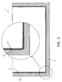
- Figure 1 schematically illustrates a first step in a building process for building a cold storage tank 1.
- a concrete floor 11 and concrete walls 12 are built, in a conventional manner.
- the walls 12 and floor 11 meet in corner areas 13.
- a first coating 21 is applied at the inner surfaces of the floor 11 and the walls 12, preferably, as shown, over the entire height of the walls 12.
- the first coating 21 is a poly-urethane material (PU), applied by spraying, to a suitable thickness of about 3 mm.
- the first coating 21 will function as a vapour barrier and gas barrier, and is adapted to be vapour-tight and gas-tight. It is also liquid-tight.
- a first PU foam layer 22 is applied on the inner surface of the coating 21.
- the first PU foam layer 22 may be applied over the full height of the walls 12 but, preferably, as shown, the first PU foam layer 22 is applied on the floor part of the coating 21 and up to a certain height on the wall part of the coating 21.
- the first PU foam layer 22 is applied by spraying, to a suitable thickness in the order of about 150 mm or more. In view of this thickness, the first PU foam layer 22 may actually be applied as a succession of multiple layers.
- the first PU foam layer 22 will function as an insulation.
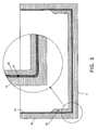
- a second PU coating 23 is applied on the inner surface of the first PU foam layer 22.
- the second PU coating 23 is applied by spraying to a suitable thickness of about 3 mm.
- the second PU coating 23 will function as a liquid barrier, and is adapted to be liquid-tight.
- the second PU coating 23 may be applied over the entire height of the walls 12, this is not always necessary.
- the first PU foam layer 22 extends over only part of the height of the wall 12, as illustrated, the second PU coating 23 should extend higher than the first PU foam layer 22 and should merge with the first PU coating 21.
- the first PU foam layer 22 is completely encapsulated.by PU coating 21, 23, in order to assure that the first PU foam layer 22 remains dry.
- a second PU foam layer 24 is applied on the inner surface of the first PU foam layer 22 and the second PU coating 23, preferably, as shown, over the entire height of the walls 12.
- the second PU foam layer 24 is applied by spraying.
- the second PU foam layer 24 will function as an insulation, together with the first PU foam layer 22.
- the combined thickness of the first PU foam layer 22 and the second PU foam layer 24 is suitably in the order of 300 mm or more.
- the thickness of the second PU foam layer 24 is reduced, whereas in locations above the first PU foam layer 22, the thickness of the second PU foam layer 24 preferably is in the order of 300 mm or more.
- the second PU foam layer 24 may actually be applied as a succession of multiple layers.
- a third PU coating 26 is applied on the inner surface of the second PU foam layer 24, preferably, as shown, over the entire height of the second PU foam layer 24.
- the third PU coating 26 is applied by spraying to a suitable thickness; a thickness of about 4-5 mm is adequate, although a thickness of about 3 mm is usually sufficient.
- the third PU coating 26 will function as a membrane, and is adapted to be liquid-tight.
- a roof on top of the tank can be done by conventional building methods, so this needs not be explained in further detail. It is noted, however, that the roof, once built, can be sprayed with foam and/or coating PU as well.
- tank-in-tank concept has disadvantages, as mentioned above, while further the tank-in-tank-concept does not fully utilize the storage capacity of the tank.
- An important advantage of the tank 1 is that the tank 1 itself is suitable to act as cold liquid container, without a separate inner vessel being necessary. Then, in operation, the cold liquid (not shown for sake of simplicity) would be in contact with the third PU coating 26.
- the first PU foam layer 22 and the second PU foam layer 24 together act as thermal insulation between the cold liquid contents and the concrete floor 11 and walls 12, the first PU coating 21 and the third PU coating 26 (the thickness of which is exaggerated in the figures) also contributing insulative capacity.
- the third PU coating 26 acts as membrane, protecting the foam 24 against entry by the cold liquid.
- the first PU coating 21 acts as barrier, protecting the foam 22, 24 against entry by moist or vapour which penetrates from the surroundings through the concrete floor 11 and walls 12.
- the second PU coating 23 does not need to come into action. Only in case of a leakage of the third PU coating 26 (and leakage of a possible inner vessel), cold liquid will enter the foam 24, and will ultimately reach the second PU coating 23. If the second PU coating 23 would be absent, the cold liquid would be separated from the concrete floor 11 and walls 12 by the first PU coating 21 only. In principle, this separation is sufficient in that no cold liquid will leak through to the concrete; in any case, the first PU coating 21 is liquid-tight. However, the thermal insulative capacity of the first PU coating 21 alone is insufficient for protecting the concrete so that, in such circumstances, the concrete would cool down to a very low temperature; as a consequence, the risks of concrete cracks increase.
- the second PU coating 23 extends over the entire floor 11, as illustrated.
- the second PU coating 23 (and the first PU foam layer 22) is arranged in the corner area only: in that case, the second PU coating 23 would extend beyond the first PU foam layer 22 and merge with the floor part of the first PU coating 21, as indicated by a dotted line 23' in figure 4 , to keep the first PU foam layer 22 encapsulated.
- the second PU coating 23 acts as a backup for the third PU coating 26, having the same mechanical properties as the third PU coating 26.
- the second PU coating 23 should be separate from the third PU coating 26 in order to prevent possible failures in the third PU coating 26 from damaging the second PU coating 23.
- the second PU coating 23 maintains sufficient insulation (i.e. first PU foam layer 22 remaining dry instead of being drenched with cold liquid) between cold liquid and concrete. It is possible to protect the entire height of the walls 12 in this way, by having the first PU foam layer 22 and the second PU coating 23 extend over the full height of the walls 12.
- the first PU foam layer 22 is as thick as possible.
- the thickness of the first PU foam layer 22 is chosen in the range 150 -250 mm, while the thickness of the second PU foam layer 24 is chosen in the range 150 - 50 mm, the combined thickness being approximately 300 mm.
- the main advantages of the present invention are associated with the building process. Once the concrete floor has been laid and the concrete walls have been erected, the entire thermal protection system can be applied by spraying, using in principle the same material (PU) for all layers. Since only one appplication technique is used, the work can be done by only one construction company (sub-contractor), which is much more efficient than having to coordinate different teams of worksmen performing different works on necessarily pre-defined times.
- PU material
- the thermal protection system does not need to contain any metal parts any more.
- thermal protection layers are made from the same material or material family (poly urethane), so that all layers have identical or at least comparable thermo-mechanical properties such as expansion/ contraction coefficient.
- a material which can very advantageously be used as gas-tight and liquid-tight coating in the present invention is a two-component poly urethane composition which is commercially available from the company TAGOS S.r.L. in Busto Arsizio, Italy, under the brand name IWR ESATEC HR 1000. In the market, this material is also known under the name IWR CRYOCOAT HR, and is commercially available under this name from the company INSU-W-RAPID B.V. in Tilburg, the Netherlands.
- the coating material is sprayed by means of a mix/spray head, and the components immediately undergo a chemical reaction which is finished after approximately 2 minutes, after which a further layer can be applied.
- the thickness of the layer to be applied can be set as desired.
- a suitable value for the thickness of the layers to be applied is in the range of 2-4 mm, but it is possible to apply thinner or thicker layers. It is noted that, in the figures, the thicknesses of the different layers are not shown to scale.
- thermal protection system it is possible to build the thermal protection system over the entire tank as a whole, i.e. to apply one layer over the entire inner surface of the tank, to apply a second layer over the entire inner surface of the tank, etc.
- such section may extend over the entire height of the wall and have a width in the order of a few meters.
- CTSR ⁇ ⁇ 1 - ⁇ E ⁇ ⁇ ⁇ T 2 - T 1
- the density and chemical formulation of the foam should preferably be selected in such a way that the CTSR-value is sufficiently high, preferably in the order of approximately 3 or higher.
- foam compositions meeting this requirement are commercially available, so it is not necessary here to give more details on the composition.
- the fixation of the thermal protection system to the floor and the walls of the tank is sufficiently strong to withstand forces that occur due to temperature variations.
- this fixation is based on adhesion between PU coating 21 and concrete, and it may be preferred to provide the walls 12 of the tank, and perhaps also the floor 11, with anchor points which offer a mechanical fixation of the PU to the concrete.
- anchor point should combine mechanical strength with little or no thermal conduction.
- FIG. 7 is a cross section illustrating an embodiment of a suitable anchor point 100 in accordance with the present invention.
- the anchor point 100 comprises a bush 110, fixed in the concrete of the wall 12, either by being embedded in the concrete when the concrete was being poured into a formwork or by being screwed into the concrete after the concrete has hardened.
- a suitable material for the bush 110 is glass fiber reinforced polyester, epoxy or phenolic resin which are materials known per se.
- the bush 110 is provided with a threaded bore, into which a screw rod 120 is screwed, so that the screw rod 120 extends substantially perpendicularly with respect to the inner surface of the wall 12.
- the screw rod 120 may be made from the same material as the bush 110.
- a first retaining plate 131 is screwed onto the screw rod 120, which first retaining plate 131 may be made from the same material as the screw rod 120.
- the first retaining plate 131 is screwed tight against the first PU foam layer 22, thus providing a mechanical fixation of the combination of the first PU coating 21 and the first PU foam layer 22.
- the second PU coating 23 is applied on the first PU foam layer 22, over the first retaining plate 131.
- a second retaining plate 132 is screwed onto the screw rod 120, which second retaining plate 132 may be made from the same material as the first retaining plate 131.
- the second retaining plate 132 is screwed tight against the second PU foam layer 24, thus providing a mechanical fixation of the second PU foam layer 24, while also adding to the fixation of the underlying layers.
- the third PU coating 26 is applied on the second PU foam layer 24, over the second retaining plate 132.
- the first retaining plate 131 may be omitted.
- the retaining plate(s) may be screwed so tight that the underlying foam layers 22 and 24 are compressed.
- the vessel of the tank 1, i.e. floor 11 and walls 12, are not necessarily made from concrete; in an alternative embodiment, they may be made from a suitable metal. Since metal is vapour-tight and gas-tight, the first PU coating 21 may be omitted in such embodiment, but the first PU coating 21 may also be maintained.
Landscapes
- Engineering & Computer Science (AREA)
- Physics & Mathematics (AREA)
- Thermal Sciences (AREA)
- Mechanical Engineering (AREA)
- General Engineering & Computer Science (AREA)
- Filling Or Discharging Of Gas Storage Vessels (AREA)
- Packages (AREA)
Priority Applications (2)
| Application Number | Priority Date | Filing Date | Title |
|---|---|---|---|
| PL04774862T PL1781982T3 (pl) | 2004-08-04 | 2004-08-04 | Zbiornik magazynowy na zimne ciecze oraz sposób nanoszenia systemu izolacji termicznej w takim zbiorniku |
| DK04774862.9T DK1781982T3 (da) | 2004-08-04 | 2004-08-04 | Opbevaringsholder til kolde væsker og fremgangsmåde til påføring af et termisk isolationssystem i en sådan beholder |
Applications Claiming Priority (1)
| Application Number | Priority Date | Filing Date | Title |
|---|---|---|---|
| PCT/NL2004/000554 WO2006014101A1 (en) | 2004-08-04 | 2004-08-04 | Storage tank for cold liquids, and method for applying a thermal insulation system in such tank |
Publications (2)
| Publication Number | Publication Date |
|---|---|
| EP1781982A1 EP1781982A1 (en) | 2007-05-09 |
| EP1781982B1 true EP1781982B1 (en) | 2009-10-14 |
Family
ID=34958480
Family Applications (1)
| Application Number | Title | Priority Date | Filing Date |
|---|---|---|---|
| EP04774862A Expired - Lifetime EP1781982B1 (en) | 2004-08-04 | 2004-08-04 | Storage tank for cold liquids, and method for applying a thermal insulation system in such tank |
Country Status (8)
| Country | Link |
|---|---|
| US (1) | US20070181586A1 (pl) |
| EP (1) | EP1781982B1 (pl) |
| AT (1) | ATE445804T1 (pl) |
| DE (1) | DE602004023657D1 (pl) |
| DK (1) | DK1781982T3 (pl) |
| ES (1) | ES2334031T3 (pl) |
| PL (1) | PL1781982T3 (pl) |
| WO (1) | WO2006014101A1 (pl) |
Cited By (1)
| Publication number | Priority date | Publication date | Assignee | Title |
|---|---|---|---|---|
| EP3850262B1 (de) * | 2018-09-11 | 2024-07-10 | Linde GmbH | Tank |
Families Citing this family (21)
| Publication number | Priority date | Publication date | Assignee | Title |
|---|---|---|---|---|
| DE112005003091T5 (de) * | 2005-03-28 | 2008-02-14 | Thermos K.K., Tsubame | Wärmeisolierter Behälter |
| DE602007005696D1 (de) * | 2006-12-06 | 2010-05-12 | Shell Int Research | Er kryogenen bedingungen |
| GB2466965A (en) * | 2009-01-15 | 2010-07-21 | Cappelen Skovholt As | Liquefied gas storage tank with curved sidewall |
| KR20110051299A (ko) * | 2009-11-05 | 2011-05-18 | 한국가스공사 | 육상용 액화가스 저장탱크의 이중방벽 및 그 형성방법 |
| US20110168722A1 (en) * | 2010-01-13 | 2011-07-14 | BDT Consultants Inc. | Full containment tank |
| US8291556B2 (en) * | 2010-04-14 | 2012-10-23 | Clarion Technologies, Inc. | Structurally reinforced casket and manufacturing method |
| US8763218B2 (en) | 2010-04-14 | 2014-07-01 | Clarion Technologies, Inc. | Structurally reinforced casket and manufacturing method |
| FR3002514B1 (fr) * | 2013-02-22 | 2016-10-21 | Gaztransport Et Technigaz | Procede de fabrication d'une barriere etanche et thermiquement isolante pour cuve de stockage |
| FR3004510B1 (fr) * | 2013-04-12 | 2016-12-09 | Gaztransport Et Technigaz | Cuve etanche et thermiquement isolante de stockage d'un fluide |
| US9272475B2 (en) * | 2013-06-03 | 2016-03-01 | Sonoco Development, Inc. | Thermally insulated VIP sandwich shipper and method of making same |
| JP6446773B2 (ja) * | 2013-11-19 | 2019-01-09 | 株式会社Ihi | 低温タンク |
| JP6331350B2 (ja) * | 2013-11-19 | 2018-05-30 | 株式会社Ihi | 低温タンク |
| CA2942865C (en) | 2014-03-28 | 2021-07-13 | Public Joint Stock Company "Transneft" | Heat insulated tank |
| WO2015147678A1 (ru) | 2014-03-28 | 2015-10-01 | Открытое акционерное общество "Акционерная компания по транспорту нефти "ТРАНСНЕФТЬ" | Способ тепловой изоляции резервуаров |
| CN104071469A (zh) * | 2014-06-30 | 2014-10-01 | 苏州安特实业有限公司 | 一种具有绝热功能的保藏箱 |
| CN104071468A (zh) * | 2014-06-30 | 2014-10-01 | 苏州安特实业有限公司 | 一种具有隔热功能的保藏箱 |
| US9920466B2 (en) | 2015-02-24 | 2018-03-20 | Clarion Technologies, Inc. | Structural foam-core panels |
| KR102384711B1 (ko) * | 2015-07-13 | 2022-04-08 | 대우조선해양 주식회사 | 단열부가 구비된 액화가스 저장 탱크 |
| KR101844840B1 (ko) * | 2017-04-04 | 2018-04-03 | (주)동성화인텍 | 초저온 저장탱크의 단열구조 |
| JP7638598B2 (ja) * | 2021-05-24 | 2025-03-04 | Basf Inoacポリウレタン株式会社 | 低温液貯槽及びその製造方法及び冷熱衝撃緩和方法 |
| US20230167333A1 (en) * | 2021-11-29 | 2023-06-01 | Owens Corning Intellectual Capital, Llc | Coated cellular glass insulation system |
Family Cites Families (9)
| Publication number | Priority date | Publication date | Assignee | Title |
|---|---|---|---|---|
| US3489311A (en) * | 1967-05-25 | 1970-01-13 | Aerojet General Co | Tanks for storage of liquefied gas |
| CA992011A (en) * | 1972-06-27 | 1976-06-29 | Mitsubishi Jukogyo Kabushiki Kaisha | Heat-insulation-lined tank for low temperature liquids and method of manufacturing the same |
| GB1436109A (en) * | 1972-08-10 | 1976-05-19 | Marine Ind Developments Ltd | Storage tanks particularly for liquefied gases |
| US3852973A (en) * | 1973-04-12 | 1974-12-10 | R Marothy | Structure for storage of liquified gas |
| FR2235330B1 (pl) * | 1973-06-27 | 1977-06-24 | Mitsubishi Chem Ind | |
| GB1525865A (en) * | 1975-09-22 | 1978-09-20 | Shell Int Research | Method of applying a layer of polyurethane foam onto a cut or ground surface of polyurethane foam |
| GB1530458A (en) * | 1975-11-22 | 1978-11-01 | Conch Int Methane Ltd | Insulation system for liquefied gas tanks |
| DE2712197A1 (de) * | 1977-03-19 | 1978-09-21 | Dyckerhoff & Widmann Ag | Doppelwandiger behaelter aus stahlbeton oder spannbeton fuer kalte fluessigkeiten, z.b. fluessiggas |
| NL1016327C2 (nl) * | 2000-10-04 | 2002-04-08 | Insulation Consulting & Procur | Voorge´soleerde opslagtank voor koude vloeistoffen. |
-
2004
- 2004-08-04 ES ES04774862T patent/ES2334031T3/es not_active Expired - Lifetime
- 2004-08-04 WO PCT/NL2004/000554 patent/WO2006014101A1/en not_active Ceased
- 2004-08-04 US US11/573,265 patent/US20070181586A1/en not_active Abandoned
- 2004-08-04 DE DE602004023657T patent/DE602004023657D1/de not_active Expired - Lifetime
- 2004-08-04 AT AT04774862T patent/ATE445804T1/de active
- 2004-08-04 DK DK04774862.9T patent/DK1781982T3/da active
- 2004-08-04 EP EP04774862A patent/EP1781982B1/en not_active Expired - Lifetime
- 2004-08-04 PL PL04774862T patent/PL1781982T3/pl unknown
Cited By (1)
| Publication number | Priority date | Publication date | Assignee | Title |
|---|---|---|---|---|
| EP3850262B1 (de) * | 2018-09-11 | 2024-07-10 | Linde GmbH | Tank |
Also Published As
| Publication number | Publication date |
|---|---|
| WO2006014101A1 (en) | 2006-02-09 |
| DK1781982T3 (da) | 2010-02-08 |
| US20070181586A1 (en) | 2007-08-09 |
| DE602004023657D1 (de) | 2009-11-26 |
| PL1781982T3 (pl) | 2010-04-30 |
| ATE445804T1 (de) | 2009-10-15 |
| EP1781982A1 (en) | 2007-05-09 |
| ES2334031T3 (es) | 2010-03-04 |
Similar Documents
| Publication | Publication Date | Title |
|---|---|---|
| EP1781982B1 (en) | Storage tank for cold liquids, and method for applying a thermal insulation system in such tank | |
| RU2430295C2 (ru) | Резервуар для хранения криогенных жидкостей | |
| CN103608258B (zh) | 液化天然气运输船的制造方法 | |
| AU2005259146B2 (en) | Container for storing liquefied gas | |
| US8387334B2 (en) | LNG containment system and method of assembling LNG containment system | |
| US3948406A (en) | Storage tanks, particularly for liquified gases | |
| US4199909A (en) | Thermally insulating, fluid-tight composite wall, prefabricated elements for constructing the same and method of constructing said wall | |
| US3929247A (en) | Cryogenic tank | |
| US3927788A (en) | Cryogenic liquid containment system | |
| CN112498581A (zh) | 一种薄膜型围护系统及应用该系统的lng船 | |
| US4032608A (en) | Cryogenic liquid containment method | |
| CN112498583A (zh) | 一种薄膜型围护系统及lng船 | |
| KR101865673B1 (ko) | 비발포성 폴리우레탄 단열 구조재 및 이를 이용한 선박의 저온 단열 화물창 | |
| WO2006047188A1 (en) | Cryogenic liquid storage structure | |
| US20040040237A1 (en) | Pre-isolated storage tank for cold liquids | |
| US3363796A (en) | Insulated cargo container | |
| EP4179249B1 (en) | Method for applying insulation to a combined cylindrical tank, a combined cylindrical tank and use thereof | |
| RU231324U1 (ru) | Угловая конструкция стационарного резервуара мембранного типа | |
| RU230171U1 (ru) | Плоская изоляционная панель с креплением для непроницаемой стенки герметичного резервуара мембранного типа | |
| JP7638598B2 (ja) | 低温液貯槽及びその製造方法及び冷熱衝撃緩和方法 | |
| KR101195802B1 (ko) | 액화 가스의 저장 용기 | |
| KR20210114404A (ko) | 저온 유체용 탱크의 단열 구조체 및 그 시공 방법 |
Legal Events
| Date | Code | Title | Description |
|---|---|---|---|
| PUAI | Public reference made under article 153(3) epc to a published international application that has entered the european phase |
Free format text: ORIGINAL CODE: 0009012 |
|
| 17P | Request for examination filed |
Effective date: 20070301 |
|
| AK | Designated contracting states |
Kind code of ref document: A1 Designated state(s): AT BE BG CH CY CZ DE DK EE ES FI FR GB GR HU IE IT LI LU MC NL PL PT RO SE SI SK TR |
|
| DAX | Request for extension of the european patent (deleted) | ||
| 17Q | First examination report despatched |
Effective date: 20080807 |
|
| GRAP | Despatch of communication of intention to grant a patent |
Free format text: ORIGINAL CODE: EPIDOSNIGR1 |
|
| GRAS | Grant fee paid |
Free format text: ORIGINAL CODE: EPIDOSNIGR3 |
|
| GRAA | (expected) grant |
Free format text: ORIGINAL CODE: 0009210 |
|
| AK | Designated contracting states |
Kind code of ref document: B1 Designated state(s): AT BE BG CH CY CZ DE DK EE ES FI FR GB GR HU IE IT LI LU MC NL PL PT RO SE SI SK TR |
|
| REG | Reference to a national code |
Ref country code: GB Ref legal event code: FG4D |
|
| REG | Reference to a national code |
Ref country code: CH Ref legal event code: EP |
|
| REG | Reference to a national code |
Ref country code: IE Ref legal event code: FG4D |
|
| REF | Corresponds to: |
Ref document number: 602004023657 Country of ref document: DE Date of ref document: 20091126 Kind code of ref document: P |
|
| REG | Reference to a national code |
Ref country code: SE Ref legal event code: TRGR |
|
| REG | Reference to a national code |
Ref country code: DK Ref legal event code: T3 |
|
| REG | Reference to a national code |
Ref country code: ES Ref legal event code: FG2A Ref document number: 2334031 Country of ref document: ES Kind code of ref document: T3 |
|
| PG25 | Lapsed in a contracting state [announced via postgrant information from national office to epo] |
Ref country code: PT Free format text: LAPSE BECAUSE OF FAILURE TO SUBMIT A TRANSLATION OF THE DESCRIPTION OR TO PAY THE FEE WITHIN THE PRESCRIBED TIME-LIMIT Effective date: 20100215 |
|
| REG | Reference to a national code |
Ref country code: PL Ref legal event code: T3 |
|
| PG25 | Lapsed in a contracting state [announced via postgrant information from national office to epo] |
Ref country code: SI Free format text: LAPSE BECAUSE OF FAILURE TO SUBMIT A TRANSLATION OF THE DESCRIPTION OR TO PAY THE FEE WITHIN THE PRESCRIBED TIME-LIMIT Effective date: 20091014 |
|
| PG25 | Lapsed in a contracting state [announced via postgrant information from national office to epo] |
Ref country code: RO Free format text: LAPSE BECAUSE OF FAILURE TO SUBMIT A TRANSLATION OF THE DESCRIPTION OR TO PAY THE FEE WITHIN THE PRESCRIBED TIME-LIMIT Effective date: 20091014 Ref country code: BG Free format text: LAPSE BECAUSE OF FAILURE TO SUBMIT A TRANSLATION OF THE DESCRIPTION OR TO PAY THE FEE WITHIN THE PRESCRIBED TIME-LIMIT Effective date: 20100114 Ref country code: EE Free format text: LAPSE BECAUSE OF FAILURE TO SUBMIT A TRANSLATION OF THE DESCRIPTION OR TO PAY THE FEE WITHIN THE PRESCRIBED TIME-LIMIT Effective date: 20091014 |
|
| PLBE | No opposition filed within time limit |
Free format text: ORIGINAL CODE: 0009261 |
|
| STAA | Information on the status of an ep patent application or granted ep patent |
Free format text: STATUS: NO OPPOSITION FILED WITHIN TIME LIMIT |
|
| PG25 | Lapsed in a contracting state [announced via postgrant information from national office to epo] |
Ref country code: CZ Free format text: LAPSE BECAUSE OF FAILURE TO SUBMIT A TRANSLATION OF THE DESCRIPTION OR TO PAY THE FEE WITHIN THE PRESCRIBED TIME-LIMIT Effective date: 20091014 Ref country code: SK Free format text: LAPSE BECAUSE OF FAILURE TO SUBMIT A TRANSLATION OF THE DESCRIPTION OR TO PAY THE FEE WITHIN THE PRESCRIBED TIME-LIMIT Effective date: 20091014 |
|
| 26N | No opposition filed |
Effective date: 20100715 |
|
| PG25 | Lapsed in a contracting state [announced via postgrant information from national office to epo] |
Ref country code: GR Free format text: LAPSE BECAUSE OF FAILURE TO SUBMIT A TRANSLATION OF THE DESCRIPTION OR TO PAY THE FEE WITHIN THE PRESCRIBED TIME-LIMIT Effective date: 20100115 |
|
| REG | Reference to a national code |
Ref country code: NL Ref legal event code: SD Effective date: 20101117 |
|
| PG25 | Lapsed in a contracting state [announced via postgrant information from national office to epo] |
Ref country code: MC Free format text: LAPSE BECAUSE OF NON-PAYMENT OF DUE FEES Effective date: 20100831 |
|
| REG | Reference to a national code |
Ref country code: CH Ref legal event code: PL |
|
| PG25 | Lapsed in a contracting state [announced via postgrant information from national office to epo] |
Ref country code: CH Free format text: LAPSE BECAUSE OF NON-PAYMENT OF DUE FEES Effective date: 20100831 Ref country code: LI Free format text: LAPSE BECAUSE OF NON-PAYMENT OF DUE FEES Effective date: 20100831 |
|
| PG25 | Lapsed in a contracting state [announced via postgrant information from national office to epo] |
Ref country code: IT Free format text: LAPSE BECAUSE OF NON-PAYMENT OF DUE FEES Effective date: 20100804 |
|
| PG25 | Lapsed in a contracting state [announced via postgrant information from national office to epo] |
Ref country code: IE Free format text: LAPSE BECAUSE OF NON-PAYMENT OF DUE FEES Effective date: 20100804 |
|
| PGRI | Patent reinstated in contracting state [announced from national office to epo] |
Ref country code: IT Effective date: 20110616 |
|
| PG25 | Lapsed in a contracting state [announced via postgrant information from national office to epo] |
Ref country code: CY Free format text: LAPSE BECAUSE OF FAILURE TO SUBMIT A TRANSLATION OF THE DESCRIPTION OR TO PAY THE FEE WITHIN THE PRESCRIBED TIME-LIMIT Effective date: 20091014 |
|
| PG25 | Lapsed in a contracting state [announced via postgrant information from national office to epo] |
Ref country code: HU Free format text: LAPSE BECAUSE OF FAILURE TO SUBMIT A TRANSLATION OF THE DESCRIPTION OR TO PAY THE FEE WITHIN THE PRESCRIBED TIME-LIMIT Effective date: 20100415 |
|
| PG25 | Lapsed in a contracting state [announced via postgrant information from national office to epo] |
Ref country code: TR Free format text: LAPSE BECAUSE OF FAILURE TO SUBMIT A TRANSLATION OF THE DESCRIPTION OR TO PAY THE FEE WITHIN THE PRESCRIBED TIME-LIMIT Effective date: 20091014 |
|
| REG | Reference to a national code |
Ref country code: GB Ref legal event code: 732E Free format text: REGISTERED BETWEEN 20121122 AND 20121128 |
|
| REG | Reference to a national code |
Ref country code: DE Ref legal event code: R082 Ref document number: 602004023657 Country of ref document: DE Representative=s name: MITSCHERLICH & PARTNER PATENT- UND RECHTSANWAE, DE |
|
| REG | Reference to a national code |
Ref country code: FR Ref legal event code: TQ Owner name: TAGOS SRL, IT Effective date: 20121214 Ref country code: FR Ref legal event code: TQ Owner name: INSULATION CONSULTING AND PROCUREMENT SERVICES, NL Effective date: 20121214 |
|
| REG | Reference to a national code |
Ref country code: NL Ref legal event code: SD Effective date: 20130116 |
|
| REG | Reference to a national code |
Ref country code: ES Ref legal event code: PC2A Owner name: INSULATION CONSULTING AND PROCUREMENT SERVICES B.V Effective date: 20130117 |
|
| REG | Reference to a national code |
Ref country code: DE Ref legal event code: R081 Ref document number: 602004023657 Country of ref document: DE Owner name: INSULATION CONSULTING AND PROCUREMENT SERVICES, NL Free format text: FORMER OWNER: TAGOS SRL,HARRY ROBERT VAN OOTMARSUM, , NL Effective date: 20130115 Ref country code: DE Ref legal event code: R082 Ref document number: 602004023657 Country of ref document: DE Representative=s name: MITSCHERLICH & PARTNER PATENT- UND RECHTSANWAE, DE Effective date: 20130115 Ref country code: DE Ref legal event code: R081 Ref document number: 602004023657 Country of ref document: DE Owner name: TAGOS SRL, IT Free format text: FORMER OWNER: TAGOS SRL,HARRY ROBERT VAN OOTMARSUM, , NL Effective date: 20130115 Ref country code: DE Ref legal event code: R082 Ref document number: 602004023657 Country of ref document: DE Representative=s name: MITSCHERLICH, PATENT- UND RECHTSANWAELTE, PART, DE Effective date: 20130115 Ref country code: DE Ref legal event code: R082 Ref document number: 602004023657 Country of ref document: DE Representative=s name: MITSCHERLICH, PATENT- UND RECHTSANWAELTE PARTM, DE Effective date: 20130115 Ref country code: DE Ref legal event code: R081 Ref document number: 602004023657 Country of ref document: DE Owner name: TAGOS SRL, IT Free format text: FORMER OWNERS: TAGOS SRL, BUSTO ARSIZIO, IT; VAN OOTMARSUM, HARRY ROBERT, GOIRLE, NL Effective date: 20130115 Ref country code: DE Ref legal event code: R081 Ref document number: 602004023657 Country of ref document: DE Owner name: INSULATION CONSULTING AND PROCUREMENT SERVICES, NL Free format text: FORMER OWNERS: TAGOS SRL, BUSTO ARSIZIO, IT; VAN OOTMARSUM, HARRY ROBERT, GOIRLE, NL Effective date: 20130115 |
|
| REG | Reference to a national code |
Ref country code: ES Ref legal event code: PC2A Owner name: TAGOS, S.R.L. Effective date: 20130319 |
|
| REG | Reference to a national code |
Ref country code: AT Ref legal event code: PC Ref document number: 445804 Country of ref document: AT Kind code of ref document: T Owner name: TAGOS SRL, IT Effective date: 20130329 Ref country code: AT Ref legal event code: PC Ref document number: 445804 Country of ref document: AT Kind code of ref document: T Owner name: INSULATION CONSULTING AND PROCUREMENT SERVICES, NL Effective date: 20130329 |
|
| PGFP | Annual fee paid to national office [announced via postgrant information from national office to epo] |
Ref country code: LU Payment date: 20130823 Year of fee payment: 10 |
|
| PGFP | Annual fee paid to national office [announced via postgrant information from national office to epo] |
Ref country code: AT Payment date: 20130828 Year of fee payment: 10 |
|
| PGFP | Annual fee paid to national office [announced via postgrant information from national office to epo] |
Ref country code: DK Payment date: 20140930 Year of fee payment: 11 |
|
| PGFP | Annual fee paid to national office [announced via postgrant information from national office to epo] |
Ref country code: GB Payment date: 20140930 Year of fee payment: 11 |
|
| PGFP | Annual fee paid to national office [announced via postgrant information from national office to epo] |
Ref country code: SE Payment date: 20140930 Year of fee payment: 11 Ref country code: FR Payment date: 20141014 Year of fee payment: 11 Ref country code: DE Payment date: 20141031 Year of fee payment: 11 Ref country code: ES Payment date: 20141001 Year of fee payment: 11 Ref country code: FI Payment date: 20141001 Year of fee payment: 11 |
|
| PGFP | Annual fee paid to national office [announced via postgrant information from national office to epo] |
Ref country code: NL Payment date: 20140930 Year of fee payment: 11 Ref country code: PL Payment date: 20141002 Year of fee payment: 11 |
|
| PG25 | Lapsed in a contracting state [announced via postgrant information from national office to epo] |
Ref country code: LU Free format text: LAPSE BECAUSE OF NON-PAYMENT OF DUE FEES Effective date: 20140804 |
|
| PGFP | Annual fee paid to national office [announced via postgrant information from national office to epo] |
Ref country code: IT Payment date: 20141014 Year of fee payment: 11 |
|
| REG | Reference to a national code |
Ref country code: AT Ref legal event code: MM01 Ref document number: 445804 Country of ref document: AT Kind code of ref document: T Effective date: 20140804 |
|
| PGFP | Annual fee paid to national office [announced via postgrant information from national office to epo] |
Ref country code: BE Payment date: 20141001 Year of fee payment: 11 |
|
| PG25 | Lapsed in a contracting state [announced via postgrant information from national office to epo] |
Ref country code: AT Free format text: LAPSE BECAUSE OF NON-PAYMENT OF DUE FEES Effective date: 20140804 |
|
| REG | Reference to a national code |
Ref country code: DE Ref legal event code: R119 Ref document number: 602004023657 Country of ref document: DE |
|
| REG | Reference to a national code |
Ref country code: DK Ref legal event code: EBP Effective date: 20150831 |
|
| REG | Reference to a national code |
Ref country code: SE Ref legal event code: EUG |
|
| GBPC | Gb: european patent ceased through non-payment of renewal fee |
Effective date: 20150804 |
|
| PG25 | Lapsed in a contracting state [announced via postgrant information from national office to epo] |
Ref country code: IT Free format text: LAPSE BECAUSE OF NON-PAYMENT OF DUE FEES Effective date: 20150804 |
|
| REG | Reference to a national code |
Ref country code: NL Ref legal event code: MM Effective date: 20150901 |
|
| PG25 | Lapsed in a contracting state [announced via postgrant information from national office to epo] |
Ref country code: FI Free format text: LAPSE BECAUSE OF NON-PAYMENT OF DUE FEES Effective date: 20150804 Ref country code: SE Free format text: LAPSE BECAUSE OF NON-PAYMENT OF DUE FEES Effective date: 20150805 |
|
| REG | Reference to a national code |
Ref country code: FR Ref legal event code: ST Effective date: 20160429 |
|
| PG25 | Lapsed in a contracting state [announced via postgrant information from national office to epo] |
Ref country code: NL Free format text: LAPSE BECAUSE OF NON-PAYMENT OF DUE FEES Effective date: 20150901 |
|
| PG25 | Lapsed in a contracting state [announced via postgrant information from national office to epo] |
Ref country code: GB Free format text: LAPSE BECAUSE OF NON-PAYMENT OF DUE FEES Effective date: 20150804 Ref country code: DE Free format text: LAPSE BECAUSE OF NON-PAYMENT OF DUE FEES Effective date: 20160301 |
|
| PG25 | Lapsed in a contracting state [announced via postgrant information from national office to epo] |
Ref country code: DK Free format text: LAPSE BECAUSE OF NON-PAYMENT OF DUE FEES Effective date: 20150831 Ref country code: FR Free format text: LAPSE BECAUSE OF NON-PAYMENT OF DUE FEES Effective date: 20150831 |
|
| REG | Reference to a national code |
Ref country code: ES Ref legal event code: FD2A Effective date: 20160927 |
|
| PG25 | Lapsed in a contracting state [announced via postgrant information from national office to epo] |
Ref country code: ES Free format text: LAPSE BECAUSE OF NON-PAYMENT OF DUE FEES Effective date: 20150805 |
|
| PG25 | Lapsed in a contracting state [announced via postgrant information from national office to epo] |
Ref country code: BE Free format text: LAPSE BECAUSE OF NON-PAYMENT OF DUE FEES Effective date: 20150831 |
|
| PG25 | Lapsed in a contracting state [announced via postgrant information from national office to epo] |
Ref country code: PL Free format text: LAPSE BECAUSE OF NON-PAYMENT OF DUE FEES Effective date: 20150804 |