EP1781992B1 - Unite d'utilisation destinee a influencer la commande d'un appareil menager - Google Patents
Unite d'utilisation destinee a influencer la commande d'un appareil menager Download PDFInfo
- Publication number
- EP1781992B1 EP1781992B1 EP05791367A EP05791367A EP1781992B1 EP 1781992 B1 EP1781992 B1 EP 1781992B1 EP 05791367 A EP05791367 A EP 05791367A EP 05791367 A EP05791367 A EP 05791367A EP 1781992 B1 EP1781992 B1 EP 1781992B1
- Authority
- EP
- European Patent Office
- Prior art keywords
- light source
- operating
- unit according
- storage means
- operating unit
- Prior art date
- Legal status (The legal status is an assumption and is not a legal conclusion. Google has not performed a legal analysis and makes no representation as to the accuracy of the status listed.)
- Expired - Lifetime
Links
Images



Classifications
-
- F—MECHANICAL ENGINEERING; LIGHTING; HEATING; WEAPONS; BLASTING
- F24—HEATING; RANGES; VENTILATING
- F24C—DOMESTIC STOVES OR RANGES ; DETAILS OF DOMESTIC STOVES OR RANGES, OF GENERAL APPLICATION
- F24C7/00—Stoves or ranges heated by electric energy
- F24C7/08—Arrangement or mounting of control or safety devices
- F24C7/082—Arrangement or mounting of control or safety devices on ranges, e.g. control panels, illumination
- F24C7/085—Arrangement or mounting of control or safety devices on ranges, e.g. control panels, illumination on baking ovens
-
- F—MECHANICAL ENGINEERING; LIGHTING; HEATING; WEAPONS; BLASTING
- F24—HEATING; RANGES; VENTILATING
- F24C—DOMESTIC STOVES OR RANGES ; DETAILS OF DOMESTIC STOVES OR RANGES, OF GENERAL APPLICATION
- F24C7/00—Stoves or ranges heated by electric energy
- F24C7/08—Arrangement or mounting of control or safety devices
- F24C7/082—Arrangement or mounting of control or safety devices on ranges, e.g. control panels, illumination
- F24C7/083—Arrangement or mounting of control or safety devices on ranges, e.g. control panels, illumination on tops, hot plates
Definitions
- the invention relates to an operating unit for influencing a control of a household appliance referred to in the preamble of claim 1-kind.
- Such a control unit is for example from the DE 198 32 757 C2 known.
- the known operating unit for influencing a cooking appliance control has a housing, on which a group of first and a group of second operating elements is arranged. Furthermore, the known operating unit has a light source for illuminating a second operating element.
- the first and second controls and the light source are electrically connected to a controller disposed in the housing and configured as an electronic controller, the controller having a processing unit and a memory.
- the illuminable second operating element and the light source are designed and arranged on the housing such that they are substantially invisible to the human eye when the light source is switched off and the light source can be switched on by actuating a first operating element.
- the local selection elements for selecting the cooking zone are backlit to display the cooking zones in operation.
- the display device has a special fluoroscopy area.
- the invention thus presents the problem of providing a control unit, in which the design and circuit complexity is reduced and at the same time the ease of use and the overall visual impression is improved.
- the achievable with the present invention consist in addition to the reduction of the design and circuitry effort in a simultaneous improvement of the ease of use and the overall visual impression.
- the ten-digit keypad is visible to the user only when he is entering numbers, for example, to enter a Garden temperature or a cooking time for a running in a cooking cooking process is needed. Otherwise, the ten-digit keypad is essentially invisible to the human eye. On the one hand, this ensures that the user is not distracted in the operation of the household appliance by controls that are not needed at the current time.
- the clarity of the control unit according to the invention is improved.
- the control unit according to the invention allows greater freedom of design and thus a better creative coordination of the control unit with the household appliance as a whole.
- a particularly advantageous embodiment of the teaching according to the invention provides that the illumination of the ten-digit keypad is designed as a backlight. In this way, the operating unit according to the invention is particularly easy to implement.
- a further advantageous embodiment provides that in the memory different types of illumination for the illumination of the ten-digit keypad are stored and in dependence of the actuated first control element or stored in the memory and callable by the processing unit for the operation of the household appliance program of the processing unit can be selected and triggered. As a result, the overall visual impression and ease of use is further improved.
- An advantageous development of the aforementioned embodiment provides that the mutually different types of illumination can be generated by a light source having a plurality of light emitting diodes. In this way, the different types of lighting can be realized in a particularly simple and cost-effective manner.
- the processing unit has a first timer, which can be activated by switching on the light source and by means of which the light source is automatically switched off after a predetermined and stored in the memory first period of time. As a result, the ease of use is further improved.
- An advantageous development of the aforementioned embodiment provides that the activated first timer in response to a predetermined and stored in the memory first off condition is deactivated. In this way it is ensured that the ten-digit keypad remains visible to the human eye until the user has completed the required number of entries to the end.
- the processing unit has a second timer that can be activated in the presence of the first switch-off condition and by means of which the light source after expiration of a previously set and stored in the memory second period of time is automatically switched off. This ensures that the illumination of the ten-digit keypad is automatically switched off after a maximum period has elapsed.
- the operating unit according to the invention is carried out as a remote control or as an independent structural unit.
- the control unit is installed in a household appliance and thus structurally integrated.
- Fig. 1 is a designed as an oven inventive household appliance shown having a control unit according to the invention.
- the household appliance with the operating unit is shown in a front view.
- the operating unit for influencing an in Fig. 1 Not shown control of the household appliance has a group of first controls 4 and a group of second controls 6, wherein the group of second controls 6 is formed as a ten-digit keypad.
- the first and second operating elements 4 and 6 are designed as touch-sensitive membrane keys.
- the group of first operating elements 4 has a border imprinted on the operating unit and perceptible to the human eye.
- the ten-digit keypad 6 is illuminated so that it is perceptible to the human eye.
- Between the two groups of controls 4 and 6 designed as a graphic display display element 8 is arranged.
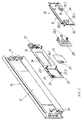
- the operating unit according to the invention is in Fig. 2 shown in an exploded view looking towards the back.
- the operating unit according to the invention has a housing 10 in which an approximately centrally disposed opening 12 is formed.
- the housing 10 To attach the housing 10 and thus the entire control unit to the in Fig. 2 Not shown body of the household appliance, the housing 10 at the two lateral ends of each mounting bracket 14.
- the operating unit has a frame part 16 designed as a circuit board, which encloses a first opening 18 and a second opening 20.
- a frame part 16 designed as a circuit board, which encloses a first opening 18 and a second opening 20.
- two projections 16.1 are formed, whose function will be explained below.
- the control element control for the two groups of controls 4 and 6 and the light source 22 is arranged, wherein the light source 22 is formed as an upper row 22.1 of a total of six light emitting diodes and a lower row 22.2 of a total of six light-emitting diodes.
- the two rows 22.1 and 22.2 are arranged along the upper and the lower edge of the opening 20 in three groups of two on the frame part 16 and electrically connected to the control element control for the two groups of controls 4 and 6.
- the frame part is dimensioned such that it completely covers the opening 12 in the housing 10 in the assembled state of the operating unit.
- the opening 20 in the frame part 16 is covered in the assembled state of the operating unit by a transparent and touch-sensitive film 24, wherein the film 24 is electrically connected via plug contacts 26 with the frame part 16.
- the numbers 0 to 9 are arranged in the manner of a ten-digit keypad 6 as transparent regions of the film 24 in a manner known to those skilled in the art. See also Fig. 4 , Opposite to the viewing direction, a frame-like light guide 28 is arranged directly behind the film 24.
- the light emitted from the light source at the top and bottom of the light guide 28 is coupled in the manner known to those skilled in the art, passed through the light guide 28 and arranged on the front side of the light guide 28 and Lichtauskoppelungslitis not shown decoupled again.
- the Lichtauskoppelungs slaughter of the light guide 28 are arranged in the assembled state of the control unit directly behind the formed as transparent areas of the film 24 individual digits 0 to 9.
- the regions of the light guide 28, which are not arranged directly behind a digit 0 to 9 of the film 24 in the assembled state of the operating unit, are essentially reduced to webs of material.
- the light guide 28 at its upper and lower ends in each case a sleeve-like holder 28.2, which in the assembled state of the operating unit with the projections 16.1 cooperate in a manner known in the art and thereby hold the light guide 28 to the frame member 16.
- the controller 30 is designed as an electronic control, which is in the assembled state of the control unit via only partially shown plug contacts 32 with the formed on the frame part 16 control element, for processing the signals from the controls 4 and 6 and their control, electrically connected. Furthermore, the controller 30 has a microprocessor-based processing unit 30.1 and a memory 30.2. The controller 30 and the black colored display element 8 are arranged on a circuit board 34 in a manner known to those skilled in the art.
- the film 24 is first inserted by means of the plug contacts 26 on the frame part 16 and thereby electrically connected to the control element control. Subsequently, the frame part 16 is attached with the attached film 24 by gluing to the housing 10 of the control unit.
- the light guide 28 is inserted by means of the sleeve-like brackets 28.2 on the projections 16.1 formed on the frame part 16 and thereby held on the frame part 16.
- the controller 30 is fixed to the frame part 16 in a manner known to those skilled in the art, such that the display element 8 completely covers the first opening 18 of the frame part 16.
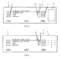
- Fig. 3 is shown on the right side of the display element 8.
- the control arrows 8.2 associated further controls 7 are arranged and also clearly marked by embossed white borders. These borders are analogous to the boundaries 4.1 in Fig. 3 shown inverted.
- the proportion shown in white in the bar display 8. 1 changes in a manner known to the person skilled in the art.
- the bar display 8.1 is represented analogously to the borders by a black border.
- the user presses the first operating element shown in the image plane above from the group of the first operating elements 4, then the light source 22 is switched on and the ten-digit keypad 6 is backlit. See also Fig. 4 , The numbers 0 to 9 are visible on the user-facing front of the human eye control unit.
- the user has the option to change the baking muffle temperature for the selected cooking process from the now-stored default temperature of 160 ° C in 1 ° C increments to any temperature from 50 ° C to 260 ° C by means of the now visible numbers 0 to 9.
- the default temperature is also inverted, that is black.
- the range of values for the selectable baking muffle temperature is likewise shown on the display element 8.
- Fig. 5 shows, as already based on Fig. 4 explained, the control unit according to the invention after confirming the set by the ten-digit keypad 6 baking muffle temperature. Since the setting of the baking muffle temperature is completed and the ten-digit keypad 6 is thus no longer needed, the light source 22 is turned off again and the ten-digit keypad 6 is no longer backlit. The ten-digit keypad 6 is no longer visible to the human eye and the control unit according to the invention has a similar appearance as in Fig. 3 , Analogous to Fig. 3 the ten-digit button block 6 is symbolized by a dashed line.
- the user also has the option of changing the cooking duration and the start time in the selected cooking program.
- the user respectively actuates the control element assigned to the corresponding text display "duration” or "start time” from the group of the first operating elements 4.
- the further sequence is analogous to the above explanations.
- the processing unit 30.1 of the controller 30 of the present embodiment has a first timer 30.1.1.
- the first timer 30.1.1 is started.
- the light source 22 is automatically turned off.
- the first switch-off condition is present and the first timer 30.1.1 is automatically stopped.
- a second timer 30.1.2 of the processing unit 30.1 is started and a second period of thirty minutes stored in the memory 30.2 begins to run. After expiration of this second time period, the second timer 30.1.2 is stopped and the light source 22 is turned off.
- Another possible embodiment of the operating unit according to the invention provides that different types of illumination for the illumination of the ten-digit keypad 6 are stored in the memory 30.2 and depending on the actuated first control element 4 or stored in the memory 30.2 and by means of the processing unit 30.1 for the operation of the household appliance callable program by the processing unit 30.1 selectable and can be triggered.
- different types of lighting different realizable colors of the backlighting of the ten-digit keypad 6 are conceivable, for example, by differently colored light emitting diodes of the light source. As a result, the overall visual impression and ease of use is further improved.
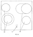
- Fig. 6 a self-sufficient hob with a control unit according to the invention.
- the hob designed as a glass ceramic plate has four cooking zones 40, of which two cooking zones 40 are formed in two parts, so that the surface of these cooking zones 40 can be selectively increased. These cooking zones 40 are shown in the image plane bottom left and top right.
- the glass ceramic plate is formed without breakthroughs.
- the group of first operating elements 4 are touch-sensitive keys which are marked on the cooktop analogously to the first exemplary embodiment, so that the position of the group of first operating elements 4 is perceptible to the human eye even when the cooktop is switched off.
- Each cooking zone 40 is associated with an operating element from the group of first operating elements, wherein their arrangement on the hob corresponds to the arrangement of the cooking zones 40.
- the group of second operating elements 6 is analogous to the first embodiment and invisible to the human eye as long as no adjustments by means of the group of second control elements 6 are required. If now the user presses one of the controls from the first group of controls 4 and thus one of the cooking zones 40 selected for user settings, the group of second controls 6, analogous to the first embodiment, backlit and thus for the human eye on the hob visible, noticeable. Please refer Fig. 7 ,
- Fig. 7 the control element arranged in the lower left of the image plane was pressed out of the group of first control elements 4.
- the actuated first operating element 4 is backlit in the present embodiment, which is in Fig. 7 symbolized by the fact that the annular cooking zone symbol is filled in black.
- the heating power level set for each cooking zone 40 is displayed on displays 8 arranged next to the individual operating elements of the first group of operating elements 4.
- the displays 8 are designed as seven-segment displays. In the present case, 40 "8" is displayed for each cooking zone 40, which corresponds to the second highest heating power level.
- symbols 42 which are not visible to the human eye until then are illuminated for the two cooking zones 40 that can be set in their surface in the manner explained above and thus can be perceived by the human eye.
- Symbols 42 indicate the location of touch-sensitive keys. For example, if the user wishes to extend the cooking zone 40 shown at the lower left of the image plane from the preset smaller area to the larger area, he will press the icon 42 shown at the lower left of the image plane. The user can now select the desired heat output level for the selected cooking zone 40 by means of set the group of second controls 6 analogous to the first embodiment.
- the numbers "0" to "9” stand for the selectable heating power levels, wherein pressing the digit "0" turns off the heating of the selected cooking zone 40.
- the user has the possibility of activating the heating time setting 44 illuminated simultaneously with the group of second operating elements 6 and in an analogous manner.
- the user must press the now visible "+” buttons of the heating time setting 44 to set the desired heating time for the selected cooking zone 40.
- the set heating time is displayed on a display 46 associated with the heating time setting 44.
- the settings for a cooking zone 40 can be made only when the desired cooking zone 40 has been selected via the group of first controls 4.
Landscapes
- Engineering & Computer Science (AREA)
- Chemical & Material Sciences (AREA)
- Combustion & Propulsion (AREA)
- Mechanical Engineering (AREA)
- General Engineering & Computer Science (AREA)
- Push-Button Switches (AREA)
- Percussion Or Vibration Massage (AREA)
- Cookers (AREA)
- Control Of Washing Machine And Dryer (AREA)
- Circuit Arrangement For Electric Light Sources In General (AREA)
- Electric Stoves And Ranges (AREA)
- Selective Calling Equipment (AREA)
Claims (8)
- Unité de manoeuvre pour agir sur une commande (30) d'un appareil ménager, avec un boîtier (10) sur lequel un groupe de premiers éléments de manoeuvre (4) et un groupe de deuxièmes éléments de manoeuvre (6) sont disposés, avec une source de lumière (22) pour éclairer un deuxième élément de manoeuvre et avec une commande (30), disposée dans le boîtier (10) et constituée en tant que commande électrique ou électronique, qui présente une unité de traitement (30.1) et une mémoire (30.2), les premiers et les deuxièmes éléments de manoeuvre (4, 6) et la source de lumière (22) étant connectés de façon électriquement conductrice à la commande (30), et le deuxième élément de manoeuvre (6) éclairable et la source de lumière (22) étant constitués et disposés sur le boîtier (10) de telle sorte que, quand la source de lumière (22) est mise hors circuit, ils sont essentiellement invisibles à l'oeil humain et la source de lumière (22) peut être mise en circuit par un actionnement d'un premier élément de manoeuvre (4),
caractérisée en ce que
le groupe de deuxièmes éléments de manoeuvre (6) est constitué sous la forme d'un bloc de touches de dix chiffres qui peut être éclairé comme un tout par la source de lumière (22) en fonction de la condition de mise en circuit déterminée au préalable et enregistrée dans la mémoire (30.2). - Unité de manoeuvre selon la revendication 1,
caractérisée en ce que
l'éclairage du bloc de touches de dix chiffres (6) est constitué en tant que rétro-éclairage. - Unité de manoeuvre selon la revendication 1 ou 2,
caractérisée en ce que
des types d'éclairage différents les uns des autres pour l'éclairage du bloc de touches de dix chiffres (6) sont enregistrés dans la mémoire (30.2) et peuvent être sélectionnés et déclenchés par l'unité de traitement (30.1) en fonction du premier élément de manoeuvre (4) actionné ou d'un programme pouvant être appelé au moyen de l'unité de traitement (30.1) pour le fonctionnement de l'appareil ménager. - Unité de manoeuvre selon la revendication 3,
caractérisée en ce que
les types d'éclairage différents les uns des autres peuvent être produits par une source de lumière (22) présentant plusieurs diodes électroluminescentes. - Unité de manoeuvre selon au moins une des revendications 1 à 4,
caractérisée en ce que
l'unité de traitement (30.1) présente un premier élément de temporisation (30.1.1) qui peut être activé par la mise en circuit de la source de lumière (22), et au moyen duquel la source de lumière (22) peut être mise hors circuit automatiquement à l'expiration d'une première plage de temps déterminée au préalable et enregistrée dans la mémoire (30.2). - Unité de manoeuvre selon la revendication 5,
caractérisée en ce que
le premier élément de temporisation (30.1.1) activé peut être désactivé en fonction d'une première condition de mise hors circuit déterminée au préalable et enregistrée dans la mémoire (30.2). - Unité de manoeuvre selon la revendication 6,
caractérisée en ce que
l'unité de traitement (30.1) présente un deuxième élément de temporisation (30.1.2) qui peut être activé en présence de la première condition de mise hors circuit et au moyen duquel la source de lumière (22) peut être mise hors circuit automatiquement à l'expiration d'une deuxième plage de temps déterminée au préalable et enregistrée dans la mémoire (30.2). - Appareil ménager dans lequel est montée une unité de manoeuvre selon au moins l'une des revendications 1 à 7.
Applications Claiming Priority (2)
| Application Number | Priority Date | Filing Date | Title |
|---|---|---|---|
| DE102004041527A DE102004041527B3 (de) | 2004-08-27 | 2004-08-27 | Bedieneinheit zur Beeinflussung einer Steuerung eines Haushaltgeräts |
| PCT/EP2005/008828 WO2006024385A1 (fr) | 2004-08-27 | 2005-08-13 | Unite d'utilisation destinee a influencer la commande d'un appareil menager |
Publications (2)
| Publication Number | Publication Date |
|---|---|
| EP1781992A1 EP1781992A1 (fr) | 2007-05-09 |
| EP1781992B1 true EP1781992B1 (fr) | 2010-03-17 |
Family
ID=35559943
Family Applications (1)
| Application Number | Title | Priority Date | Filing Date |
|---|---|---|---|
| EP05791367A Expired - Lifetime EP1781992B1 (fr) | 2004-08-27 | 2005-08-13 | Unite d'utilisation destinee a influencer la commande d'un appareil menager |
Country Status (6)
| Country | Link |
|---|---|
| US (1) | US20090040090A1 (fr) |
| EP (1) | EP1781992B1 (fr) |
| AT (1) | ATE461400T1 (fr) |
| CA (1) | CA2576796C (fr) |
| DE (2) | DE102004041527B3 (fr) |
| WO (1) | WO2006024385A1 (fr) |
Families Citing this family (10)
| Publication number | Priority date | Publication date | Assignee | Title |
|---|---|---|---|---|
| DE102007029174A1 (de) * | 2007-06-25 | 2009-01-08 | BSH Bosch und Siemens Hausgeräte GmbH | Bedien- und Anzeigevorrichtung |
| DE102007029193A1 (de) * | 2007-06-25 | 2009-01-08 | BSH Bosch und Siemens Hausgeräte GmbH | Bedienvorrichtung |
| DE102007033276A1 (de) * | 2007-07-17 | 2009-01-22 | BSH Bosch und Siemens Hausgeräte GmbH | Hausgeräteeingabeeinheit, insbesondere für ein Kochfeld |
| DE102008025985A1 (de) | 2008-05-30 | 2009-12-03 | Rational Ag | Anzeigeeinrichtung und Gargerät damit |
| EP2192350A1 (fr) * | 2008-11-15 | 2010-06-02 | Electrolux Home Products Corporation N.V. | Panneau de commande pour contrôler plusieurs fonctions différentes d'un appareil |
| DE102010000874A1 (de) * | 2010-01-13 | 2011-07-14 | BSH Bosch und Siemens Hausgeräte GmbH, 81739 | Bedieneinrichtung für ein Hausgerät sowie Hausgerät mit einer Bedieneinrichtung |
| WO2014101930A1 (fr) * | 2012-12-24 | 2014-07-03 | Arcelik Anonim Sirketi | Lave-vaisselle présentant des moyens d'indication visuellement améliorés |
| EP2752623B1 (fr) * | 2013-01-08 | 2020-09-09 | Electrolux Home Products Corporation N.V. | Plaque de cuisson avec équipement d'éclairage |
| US10782026B2 (en) * | 2018-05-09 | 2020-09-22 | Takisha Schulterbrandt | Appparatus and method for positioning a cooking instrument |
| DE102020210559B4 (de) * | 2020-08-20 | 2022-03-31 | E.G.O. Elektro-Gerätebau GmbH | Bedieneinrichtung für ein Haushaltsgerät, Haushaltsgerät sowie Verfahren zur Anzeige einer Information an einem Haushaltsgerät |
Family Cites Families (9)
| Publication number | Priority date | Publication date | Assignee | Title |
|---|---|---|---|---|
| DE3010715A1 (de) * | 1980-03-20 | 1981-09-24 | Bauknecht Gmbh G | Bedienungstableau |
| DE3133176C1 (de) * | 1981-08-21 | 1982-10-28 | Bosch-Siemens Hausgeräte GmbH, 7000 Stuttgart | Anzeige- und Bedieneinheit für rechnergesteuerte, elektrische Haushaltgeräte |
| DE19832757C2 (de) * | 1997-07-22 | 2002-10-02 | Aeg Hausgeraete Gmbh | Verfahren zum Steuern eines Gargerätes, einer Waschmaschine oder einer Geschirrspülmaschine und Gargerät, Waschmaschine oder Geschirrspülmaschine mit grafischer Anzeigeeinrichtung |
| JP2001025982A (ja) * | 1999-07-13 | 2001-01-30 | Makita Corp | 操作性が向上した照明装置付き電動工具とその使用方法 |
| JP3941481B2 (ja) * | 2000-12-22 | 2007-07-04 | セイコーエプソン株式会社 | 液晶表示装置および電子機器 |
| US20020190057A1 (en) * | 2001-06-19 | 2002-12-19 | Bsh Home Appliances Corporation | Cooktop control |
| US6720863B2 (en) * | 2001-08-16 | 2004-04-13 | Wildseed Ltd. | Mobile electronic communication device with lights to indicate received messages |
| US7631593B2 (en) * | 2002-07-31 | 2009-12-15 | Food Equipment Technologies Company, Inc. | Food processing apparatus with auto-directive controller and method |
| DE10236718A1 (de) * | 2002-08-06 | 2004-02-12 | E.G.O. Control Systems Gmbh & Co. Kg | Elektrohaushaltsgerät mit Anzeigeeinrichtung |
-
2004
- 2004-08-27 DE DE102004041527A patent/DE102004041527B3/de not_active Expired - Fee Related
-
2005
- 2005-08-13 AT AT05791367T patent/ATE461400T1/de not_active IP Right Cessation
- 2005-08-13 US US11/573,960 patent/US20090040090A1/en not_active Abandoned
- 2005-08-13 EP EP05791367A patent/EP1781992B1/fr not_active Expired - Lifetime
- 2005-08-13 CA CA2576796A patent/CA2576796C/fr not_active Expired - Fee Related
- 2005-08-13 WO PCT/EP2005/008828 patent/WO2006024385A1/fr not_active Ceased
- 2005-08-13 DE DE502005009242T patent/DE502005009242D1/de not_active Expired - Lifetime
Also Published As
| Publication number | Publication date |
|---|---|
| ATE461400T1 (de) | 2010-04-15 |
| CA2576796C (fr) | 2011-01-18 |
| DE102004041527B3 (de) | 2006-03-02 |
| CA2576796A1 (fr) | 2006-03-09 |
| US20090040090A1 (en) | 2009-02-12 |
| WO2006024385A1 (fr) | 2006-03-09 |
| EP1781992A1 (fr) | 2007-05-09 |
| DE502005009242D1 (de) | 2010-04-29 |
Similar Documents
| Publication | Publication Date | Title |
|---|---|---|
| EP0009249A1 (fr) | Dispositif d'affichage et de manipulage d'appareils électriques | |
| EP2282126B1 (fr) | Hotte aspirante dotée d'une unité de commande | |
| DE102013223934A1 (de) | Haushaltsgerät | |
| DE102004041527B3 (de) | Bedieneinheit zur Beeinflussung einer Steuerung eines Haushaltgeräts | |
| EP0213443A1 (fr) | Disposition pour commander des consommateurs d'éléctricité dans des fours domestiques | |
| EP2079964B1 (fr) | Appareil ménager à bouton rotatif | |
| EP1908333B1 (fr) | Procede de commande d un dispositif chauffant d'un appareil electrique chauffant a plusieurs dispositifs chauffants | |
| DE10148897A1 (de) | Steuereinrichtung zur Steuerung von Elektrohaushaltsgeräten | |
| DE10211047B4 (de) | Anordnung zur Steuerung eines Kochfeldes | |
| DE4010998A1 (de) | Elektronisches geraet zur steuerung von verbrauchern | |
| EP1418384B1 (fr) | Système d'affichage avec dispositif d'éclairage pour appareil électroménager | |
| EP1449300A2 (fr) | Appareil electromenager | |
| DE3010714A1 (de) | Bedienungstableau | |
| DE3010715A1 (de) | Bedienungstableau | |
| DE10054953B4 (de) | Grundlayout und seine Verwendung für eine Bedien- und Anzeigeeinheit einer Kochmulde sowie Verfahren zur Herstellung einer Bedien- und Anzeigeeinheit für Kochmulden | |
| DE10228237B3 (de) | Bedienungseinrichtung für einen Kochherd und Verfahren zur Bedienung derselben | |
| EP1485786A2 (fr) | Ecran tactile | |
| EP1486733B1 (fr) | appareil de four cuisiniere | |
| DE102005032088A1 (de) | Hausgerät, insbesondere Gargerät mit berührungsempfindlichem Stellstreifen | |
| DE4407741C2 (de) | Einrichtung zum Ein- und Ausschalten eines elektrischen Verbrauchers | |
| DE29911917U1 (de) | Standherd | |
| DD292069A5 (de) | Anordnung zur ansteuerung von heizzeitspannen und heizleistungen fuer herde | |
| DE102004038826A1 (de) | Verfahren und Vorrichtung zur Steuerung eines Elektrogeräts mit mehreren elektrischen Verbrauchern | |
| EP0982972B1 (fr) | Dispositif de commutation dans un chauffage électrique | |
| DE102005042223A1 (de) | Anzeigentableau für ein Haushaltsgerät |
Legal Events
| Date | Code | Title | Description |
|---|---|---|---|
| PUAI | Public reference made under article 153(3) epc to a published international application that has entered the european phase |
Free format text: ORIGINAL CODE: 0009012 |
|
| 17P | Request for examination filed |
Effective date: 20070201 |
|
| AK | Designated contracting states |
Kind code of ref document: A1 Designated state(s): AT BE BG CH CY CZ DE DK EE ES FI FR GB GR HU IE IS IT LI LT LU LV MC NL PL PT RO SE SI SK TR |
|
| DAX | Request for extension of the european patent (deleted) | ||
| GRAP | Despatch of communication of intention to grant a patent |
Free format text: ORIGINAL CODE: EPIDOSNIGR1 |
|
| GRAS | Grant fee paid |
Free format text: ORIGINAL CODE: EPIDOSNIGR3 |
|
| GRAA | (expected) grant |
Free format text: ORIGINAL CODE: 0009210 |
|
| AK | Designated contracting states |
Kind code of ref document: B1 Designated state(s): AT BE BG CH CY CZ DE DK EE ES FI FR GB GR HU IE IS IT LI LT LU LV MC NL PL PT RO SE SI SK TR |
|
| REG | Reference to a national code |
Ref country code: GB Ref legal event code: FG4D Free format text: NOT ENGLISH |
|
| REG | Reference to a national code |
Ref country code: CH Ref legal event code: EP |
|
| REG | Reference to a national code |
Ref country code: IE Ref legal event code: FG4D |
|
| REF | Corresponds to: |
Ref document number: 502005009242 Country of ref document: DE Date of ref document: 20100429 Kind code of ref document: P |
|
| REG | Reference to a national code |
Ref country code: GB Ref legal event code: 746 Effective date: 20100428 |
|
| REG | Reference to a national code |
Ref country code: NL Ref legal event code: VDEP Effective date: 20100317 |
|
| PG25 | Lapsed in a contracting state [announced via postgrant information from national office to epo] |
Ref country code: LT Free format text: LAPSE BECAUSE OF FAILURE TO SUBMIT A TRANSLATION OF THE DESCRIPTION OR TO PAY THE FEE WITHIN THE PRESCRIBED TIME-LIMIT Effective date: 20100317 |
|
| LTIE | Lt: invalidation of european patent or patent extension |
Effective date: 20100317 |
|
| PG25 | Lapsed in a contracting state [announced via postgrant information from national office to epo] |
Ref country code: LV Free format text: LAPSE BECAUSE OF FAILURE TO SUBMIT A TRANSLATION OF THE DESCRIPTION OR TO PAY THE FEE WITHIN THE PRESCRIBED TIME-LIMIT Effective date: 20100317 Ref country code: FI Free format text: LAPSE BECAUSE OF FAILURE TO SUBMIT A TRANSLATION OF THE DESCRIPTION OR TO PAY THE FEE WITHIN THE PRESCRIBED TIME-LIMIT Effective date: 20100317 Ref country code: PL Free format text: LAPSE BECAUSE OF FAILURE TO SUBMIT A TRANSLATION OF THE DESCRIPTION OR TO PAY THE FEE WITHIN THE PRESCRIBED TIME-LIMIT Effective date: 20100317 Ref country code: SI Free format text: LAPSE BECAUSE OF FAILURE TO SUBMIT A TRANSLATION OF THE DESCRIPTION OR TO PAY THE FEE WITHIN THE PRESCRIBED TIME-LIMIT Effective date: 20100317 |
|
| REG | Reference to a national code |
Ref country code: IE Ref legal event code: FD4D |
|
| PG25 | Lapsed in a contracting state [announced via postgrant information from national office to epo] |
Ref country code: EE Free format text: LAPSE BECAUSE OF FAILURE TO SUBMIT A TRANSLATION OF THE DESCRIPTION OR TO PAY THE FEE WITHIN THE PRESCRIBED TIME-LIMIT Effective date: 20100317 Ref country code: CY Free format text: LAPSE BECAUSE OF FAILURE TO SUBMIT A TRANSLATION OF THE DESCRIPTION OR TO PAY THE FEE WITHIN THE PRESCRIBED TIME-LIMIT Effective date: 20100317 Ref country code: GR Free format text: LAPSE BECAUSE OF FAILURE TO SUBMIT A TRANSLATION OF THE DESCRIPTION OR TO PAY THE FEE WITHIN THE PRESCRIBED TIME-LIMIT Effective date: 20100618 Ref country code: NL Free format text: LAPSE BECAUSE OF FAILURE TO SUBMIT A TRANSLATION OF THE DESCRIPTION OR TO PAY THE FEE WITHIN THE PRESCRIBED TIME-LIMIT Effective date: 20100317 Ref country code: RO Free format text: LAPSE BECAUSE OF FAILURE TO SUBMIT A TRANSLATION OF THE DESCRIPTION OR TO PAY THE FEE WITHIN THE PRESCRIBED TIME-LIMIT Effective date: 20100317 Ref country code: SE Free format text: LAPSE BECAUSE OF FAILURE TO SUBMIT A TRANSLATION OF THE DESCRIPTION OR TO PAY THE FEE WITHIN THE PRESCRIBED TIME-LIMIT Effective date: 20100317 Ref country code: ES Free format text: LAPSE BECAUSE OF FAILURE TO SUBMIT A TRANSLATION OF THE DESCRIPTION OR TO PAY THE FEE WITHIN THE PRESCRIBED TIME-LIMIT Effective date: 20100628 |
|
| PG25 | Lapsed in a contracting state [announced via postgrant information from national office to epo] |
Ref country code: BG Free format text: LAPSE BECAUSE OF FAILURE TO SUBMIT A TRANSLATION OF THE DESCRIPTION OR TO PAY THE FEE WITHIN THE PRESCRIBED TIME-LIMIT Effective date: 20100617 Ref country code: IS Free format text: LAPSE BECAUSE OF FAILURE TO SUBMIT A TRANSLATION OF THE DESCRIPTION OR TO PAY THE FEE WITHIN THE PRESCRIBED TIME-LIMIT Effective date: 20100717 Ref country code: SK Free format text: LAPSE BECAUSE OF FAILURE TO SUBMIT A TRANSLATION OF THE DESCRIPTION OR TO PAY THE FEE WITHIN THE PRESCRIBED TIME-LIMIT Effective date: 20100317 Ref country code: CZ Free format text: LAPSE BECAUSE OF FAILURE TO SUBMIT A TRANSLATION OF THE DESCRIPTION OR TO PAY THE FEE WITHIN THE PRESCRIBED TIME-LIMIT Effective date: 20100317 |
|
| PLBE | No opposition filed within time limit |
Free format text: ORIGINAL CODE: 0009261 |
|
| STAA | Information on the status of an ep patent application or granted ep patent |
Free format text: STATUS: NO OPPOSITION FILED WITHIN TIME LIMIT |
|
| PG25 | Lapsed in a contracting state [announced via postgrant information from national office to epo] |
Ref country code: DK Free format text: LAPSE BECAUSE OF FAILURE TO SUBMIT A TRANSLATION OF THE DESCRIPTION OR TO PAY THE FEE WITHIN THE PRESCRIBED TIME-LIMIT Effective date: 20100317 Ref country code: IE Free format text: LAPSE BECAUSE OF FAILURE TO SUBMIT A TRANSLATION OF THE DESCRIPTION OR TO PAY THE FEE WITHIN THE PRESCRIBED TIME-LIMIT Effective date: 20100317 Ref country code: PT Free format text: LAPSE BECAUSE OF FAILURE TO SUBMIT A TRANSLATION OF THE DESCRIPTION OR TO PAY THE FEE WITHIN THE PRESCRIBED TIME-LIMIT Effective date: 20100719 |
|
| 26N | No opposition filed |
Effective date: 20101220 |
|
| BERE | Be: lapsed |
Owner name: MIELE & CIE. K.G. Effective date: 20100831 |
|
| PG25 | Lapsed in a contracting state [announced via postgrant information from national office to epo] |
Ref country code: MC Free format text: LAPSE BECAUSE OF NON-PAYMENT OF DUE FEES Effective date: 20100831 |
|
| REG | Reference to a national code |
Ref country code: CH Ref legal event code: PL |
|
| PG25 | Lapsed in a contracting state [announced via postgrant information from national office to epo] |
Ref country code: LI Free format text: LAPSE BECAUSE OF NON-PAYMENT OF DUE FEES Effective date: 20100831 Ref country code: CH Free format text: LAPSE BECAUSE OF NON-PAYMENT OF DUE FEES Effective date: 20100831 |
|
| PG25 | Lapsed in a contracting state [announced via postgrant information from national office to epo] |
Ref country code: BE Free format text: LAPSE BECAUSE OF NON-PAYMENT OF DUE FEES Effective date: 20100831 |
|
| PG25 | Lapsed in a contracting state [announced via postgrant information from national office to epo] |
Ref country code: AT Free format text: LAPSE BECAUSE OF NON-PAYMENT OF DUE FEES Effective date: 20100813 |
|
| PG25 | Lapsed in a contracting state [announced via postgrant information from national office to epo] |
Ref country code: LU Free format text: LAPSE BECAUSE OF NON-PAYMENT OF DUE FEES Effective date: 20100813 Ref country code: HU Free format text: LAPSE BECAUSE OF FAILURE TO SUBMIT A TRANSLATION OF THE DESCRIPTION OR TO PAY THE FEE WITHIN THE PRESCRIBED TIME-LIMIT Effective date: 20100918 |
|
| PG25 | Lapsed in a contracting state [announced via postgrant information from national office to epo] |
Ref country code: TR Free format text: LAPSE BECAUSE OF FAILURE TO SUBMIT A TRANSLATION OF THE DESCRIPTION OR TO PAY THE FEE WITHIN THE PRESCRIBED TIME-LIMIT Effective date: 20100317 |
|
| PGFP | Annual fee paid to national office [announced via postgrant information from national office to epo] |
Ref country code: DE Payment date: 20140813 Year of fee payment: 10 |
|
| PGFP | Annual fee paid to national office [announced via postgrant information from national office to epo] |
Ref country code: GB Payment date: 20140821 Year of fee payment: 10 Ref country code: FR Payment date: 20140819 Year of fee payment: 10 |
|
| PGFP | Annual fee paid to national office [announced via postgrant information from national office to epo] |
Ref country code: IT Payment date: 20140825 Year of fee payment: 10 |
|
| REG | Reference to a national code |
Ref country code: DE Ref legal event code: R119 Ref document number: 502005009242 Country of ref document: DE |
|
| GBPC | Gb: european patent ceased through non-payment of renewal fee |
Effective date: 20150813 |
|
| PG25 | Lapsed in a contracting state [announced via postgrant information from national office to epo] |
Ref country code: IT Free format text: LAPSE BECAUSE OF NON-PAYMENT OF DUE FEES Effective date: 20150813 |
|
| REG | Reference to a national code |
Ref country code: FR Ref legal event code: ST Effective date: 20160429 |
|
| PG25 | Lapsed in a contracting state [announced via postgrant information from national office to epo] |
Ref country code: GB Free format text: LAPSE BECAUSE OF NON-PAYMENT OF DUE FEES Effective date: 20150813 Ref country code: DE Free format text: LAPSE BECAUSE OF NON-PAYMENT OF DUE FEES Effective date: 20160301 |
|
| PG25 | Lapsed in a contracting state [announced via postgrant information from national office to epo] |
Ref country code: FR Free format text: LAPSE BECAUSE OF NON-PAYMENT OF DUE FEES Effective date: 20150831 |