EP1782392B1 - Vorrichtung und verfahren zur selbstbedienungs-bargeldauszahlung - Google Patents
Vorrichtung und verfahren zur selbstbedienungs-bargeldauszahlung Download PDFInfo
- Publication number
- EP1782392B1 EP1782392B1 EP05771423.0A EP05771423A EP1782392B1 EP 1782392 B1 EP1782392 B1 EP 1782392B1 EP 05771423 A EP05771423 A EP 05771423A EP 1782392 B1 EP1782392 B1 EP 1782392B1
- Authority
- EP
- European Patent Office
- Prior art keywords
- coin
- machine
- coins
- receptacles
- entrances
- Prior art date
- Legal status (The legal status is an assumption and is not a legal conclusion. Google has not performed a legal analysis and makes no representation as to the accuracy of the status listed.)
- Expired - Lifetime
Links
Images





Classifications
-
- G—PHYSICS
- G07—CHECKING-DEVICES
- G07D—HANDLING OF COINS OR VALUABLE PAPERS, e.g. TESTING, SORTING BY DENOMINATIONS, COUNTING, DISPENSING, CHANGING OR DEPOSITING
- G07D3/00—Sorting a mixed bulk of coins into denominations
-
- G—PHYSICS
- G07—CHECKING-DEVICES
- G07D—HANDLING OF COINS OR VALUABLE PAPERS, e.g. TESTING, SORTING BY DENOMINATIONS, COUNTING, DISPENSING, CHANGING OR DEPOSITING
- G07D9/00—Counting coins; Handling of coins not provided for in the other groups of this subclass
Definitions
- the present invention relates to self-service cash redemption machines and methods in which a substantial batch of unsorted coinage is fed in bulk into a hopper and is processed for collection while providing the user with a voucher or a form of credit, on a card, for example.
- the invention relates to a system and to a method in which a substantial number of unsorted coins (greater than the amounts spent in vending machines for purchasing items) are deposited in the machine.
- the coins are sorted and counted to determine a total value.
- the user is issued a voucher for an amount related to the total value.
- ATM machines have generally been limited to dispensing small amounts of change for a dollar, cash withdrawals in the form of bills, or pre-rolled rolls of coin.
- the large cash handling machines for gaming establishments sort the change into bins, which must then be emptied and further processed before being placed in a dispenser or distributed to customers through cashiers.
- U.S. Pat. Nos. 6,318,557 shows a system with a first manifold, exit chutes, and rotating coin distributors for distributing coins to manifolds which feed coins to coin receptacles.
- Magee et al. U.S. Pat. No. 6,245,545 , shows a system for separating pennies from other denominations and sending the pennies and non-pennies to two respective chambers, because it is said that pennies constitute up to seventy-five percent of the coins deposited in self-service machines.
- EP-A-0391403 describes a bag switching system for a coin sorting apparatus in which a coin switching module is provided to convey coins selectively between one of two coin bags. This allows a full bag to be replaced while coins continue to be dispensed to the other bag.
- the machine should be easy and convenient to service, to maintain and to remove the accumulated coinage.
- the machine should be capable of dispensing a receipt, a voucher or a form of credit.
- a cash redemption machine for receiving a batch of unsorted coinage from a user, for sorting coins into a plurality of denominations and for dispensing a receipt, a voucher or a form of credit to the user comprises:
- a method comprises receiving a batch of unsorted coinage from a user, for sorting coins into a plurality of denominations and for dispensing a voucher or a form of credit to the user, the method further comprising; directing coins of respective denominations from a sorting mechanism through respective chutes; wherein a compartment is provided for containing two rows of coin receptacles with at least five coin receptacles in each row; wherein coin receptacle entrances are provided for the coin receptacles to be located in the compartment; and the method being further characterized by positioning a plurality of coin diverter mechanisms between the two rows of coin receptacle entrances for pivoting to reach a varying number of coin receptacle entrances according to a coin distribution plan, including repositioning a first coin diverter mechanism located at an exit of the first chute from a first position to least two other positions that are aligned with respective coin receptacles for selectively transferring
- the invention relates to a method and a machine for receiving a batch of unsorted coinage from a user, for sorting coins into a plurality of denominations and for dispensing a receipt, a voucher or a form of credit to the user, in which coins of at least one denomination are conveyed from the sorter to a first coin receptacle; and in which a coin diverter mechanism is repositioned from a first position to at least two other positions in alignment with respective entrances for at least two other coin receptacles for that denomination.
- the diverters are repositioned to align with each of the coin receptacles, and therefore, the use of additional manifolds for routing the coins is unnecessary.
- the invention also provides for selectable unique coin distributions based on the volume of different denominations received in self-service machines.
- the diverter mechanisms can be reconfigured or adjusted to distribute coins to a plurality of from one to four receptacles depending on the coin distribution plan.
- the diverter mechanisms may be supported on a common rigid support that aids alignment with the various other parts from which coins are received and then distributed.
- the support is slidable out of the machine for servicing the parts.
- the machine provides advantageous configurations of the coin collection receptacles by arranging them in a 2x6 matrix accessible through a side door in a two-deep configuration.
- a 2x5 or 2x4 matrix would also be particularly advantageous, however the coin diverter arrangement of configurations as well.
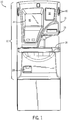
- Fig. 1 shows a self-service cash redemption machine 10 in accordance with the present invention.
- the machine is housed in an cabinet enclosure 11 having a front door panel 12 secured by a key lock 13.
- the cabinet is substantially opaque, however, one or two inconspicuous windows may be provided for viewing the internal mechanisms of the machine for servicing purposes.
- the upper panel 12 has an opening 14 for viewing a visual display screen 15.
- Below this screen 15 are two buttons 80, identified as "A" and "B", for allowing the user to enter selections of items on the screen 15.
- To the right of the display is an area for an advertising display 16 and below that is a printout slot 17 for receiving a receipt or other printable matter that exits a printer installed inside the enclosure 11.
- a coin intake area with a tray 18 that can be lifted to allow coins to slide into the machine 10.
- the coin intake tray 18 can receive a batch of unsorted coins of mixed denomination and is lifted to feed them into the machine through an opening 18a ( Fig. 3 ) to a coin processing assembly 21 ( Fig. 4 ) inside the machine 10.
- This batch of coins is greater in amount than the coins typically inserted into a vending machine, for example, to purchase a product.
- the batch of coins can be supplemented as the machine is operating so that it can process anywhere from a few dollars to perhaps two hundred dollars in U.S. coinage.
- Figs. 2 and 3 there are side access doors 19 on opposite sides (one side being shown in the drawings), which can be opened to install and remove coin receptacles, which in this instance are coin bags that would be attached to coin bag holders.
- the bags are kept separate by dividers 61 rising from a base plate 62 in the bottom of the cabinet enclosure 11.
- the machine provides an advantageous configuration of the coin collection receptacles by arranging them in a 2x6 matrix accessible through the side door 19 in a two-deep configuration, as will be apparent from the detailed description of the figures which follow.
- Other advantageous configurations such as 2x4 or 2x5 might also be used.
- Fig. 4 shows the machine with the front panels 12 and 13 removed.
- the printer 20 is now visible, along with a coin processing assembly 21 that is supported and an elongated one-piece cast member 40 that can slide forward and out of the enclosure for servicing other components in the machine 10.
- the printer 20 operates under the control of a personal computer (PC) 50, which is shown as a box in Fig. 4 .
- the personal computer 50 also controls the display 15.
- Also seen in an interior of the cabinet 11 is a service keyboard 52, a controller 53 and a power supply 54.
- the controller 53 is also connected to the I/O devices such as the count sensors on a sorting mechanism 22 and others devices to be described herein.
- the printer 20 can print out a voucher or receipt 90 as seen in Fig. 3 representing the amount of coinage fed into the coin processing assembly 21 and counted by the controller 53 through sensing devices on the sorting mechanism 22 of the coin processing assembly 21.
- the user can present this voucher or receipt 90 in payment for merchandise, or could, where permitted, redeem it for cash in the form of notes and a small amount of change less than one dollar.
- An output device for issuing a card with a pre-paid credit amount like a phone card, could also be used in place of the printer.
- Fig. 5 shows the details of the coin processing assembly 21 including a sorting mechanism 22 of same kind as is commercially available in the assignee's Mach ® 6 line of dual disc coin sorters.
- the coins are deposited on a queueing disc and transferred to a sorting plate where they fall through slots sized for different denominations.
- dual disc sorters the disclosures in Adams et al, U.S. Pat. Nos. 5,295,899 and 5,525,104 and Adams et al., U.S. Pat. No. 5,992,602, issued Nov. 30, 1999 , and Zwieg et al., U.S. Pat. No. 6,640,956, issued Nov. 4, 2003 , are referred.
- the sorting mechanism 22 is inclined at an angle of from ten to fifteen degrees to assist in removal of spurious matter that may be introduced into the sorter with the batch of coins.
- the base 23 of the sorting mechanism 22 forms coin exit spouts 24 for each denomination and a plurality of upper elbow couplings 25 are connected to the respective spouts 24 to receive the respective denominations.
- the elbow couplings 25 are further connected to chutes 26, one for each denomination.
- there is an offsort opening that is coupled through one of the coin exit spouts 24 to a chute 27 that returns offsorted coins (coins of another country for example) through the chute 27 to an opening 28 in front of the enclosure 11 ( Fig. 1 ).
- the offsort chute 27 is configured in a straight-line configuration in this embodiment, but could be constructed in other configurations that are not straight.
- the sorting mechanism 22 is configured to sort the U.S. set of coinage including pennies, nickels, dimes, quarters, half dollars and U.S. dollar coins. It is also possible to sort U.S. dollar coins. And, it is also possible to configure the sorting mechanism 22 to sort euros or coins of other coin sets such as the coins of Canada.
- the chutes 26 are further coupled through lower elbow couplings 29 to diverter mechanisms 30.
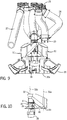
- An individual diverter mechanism 30 is seen in Fig. 10 . It has a downwardly sloped chute portion 31 that extends radially from a cylindrical entrance 32 to an exit spout 33.
- the cylindrical entrance 32 is formed around a pivot axis 32a for the diverter mechanism 30, while the cylindrical exit spout 33 is also situated about a central axis 33a.
- This diverter exit spout 33 will be aligned with a circular entrance 42 for a coin receptacle 60 that is formed in a bottom of the chassis 40 as seen in Fig. 11 .
- a lip is formed around the entrance 42 but such a lip is not necessary and could be absent in other embodiments.
- the entrances 32 and the exit spouts 33 of the diverter chutes 31 both clear respective parts of the machine located above and below them without contacting such parts.
- each receptacle entrance 42 is a bag spout assembly 34 for attaching a coin bag to receive coins.
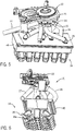
- the twelve bag spout assemblies 34 are seen in Fig. 6 , 7 , 8 and 9 . These are described and shown in U.S. Pat. No. 6,004,200, issued Dec. 21, 1999 .
- a bag spout 35 is pivoted in and out of a clip member 35a, and when the spout 35 is pivoted inward it traps the top edge of a coin bag 60 to hold the coin bag in position around the bag spout 35, as seen in Fig. 3 , to receive a stream of coins.
- the diverter mechanism 30 includes a stepper motor 36 seen in Fig. 10 .
- the diverter mechanisms 30 are mounted on the chassis 40 with the stepper motors 36 disposed in a central trench 41 in the chassis 20 as seen in Figs. 7, 8 , 9 and 11 .
- the chassis 40 is a preferably a cast aluminum member that is substantially rigid to assist alignment of the parts conveying the coins.
- the diverter chute 31 is rotated through a shaft and gearing arrangement that is driven by the stepper motor 36.
- a collar 37 rotates with the diverter chute 31 and the collar 37 has interrupter tabs 38 or markers that are sensed by a sensor 39 to sense eight possible positions for each diverter chute 31.
- Each interrupter tab 38 is of a different width so that each has its own unique identity.
- the interrupter tabs 38 pass through a light beam of the sensor 39 so the leading and trailing edges can be detected.
- the number of stepper motor pulses between the leading and trailing edges determines the interrupter tab width.
- the coin diverter 30 While processing coins, the coin diverter 30 is located in the center of one of the interrupter tabs and held in place by applying power to the stepper motor 36.
- the controller 53 provides for pivoting the diverter over four possible coin entrances 42, however, the diverter mechanisms 30, except the one for pennies, are more usually repositioned among two or three coin entrances 42 in the examples given below.
- the coin diverter mechanism 30 is rigidly cantilevered from the shaft bearing assembly and can freely pivot without frictional resistance due design clearance at the coin entrance and distribution point of the diverter 38.
- Figs. 12a and 12b Two possible distribution arrangements are functionally illustrated in Figs. 12a and 12b .
- the coins are distributed to entrances 42 for three receptacles for pennies, three receptacles for quarters, two receptacles for nickels, and two receptacles for dimes.
- the diverter mechanisms 30a, 30b for pennies and quarters are repositioned from alignment with an entrance 42 for one receptacle to alignment with entrances 42 for two other receptacles under the control of the controller 50.
- the diverter mechanisms 30c, 30d for nickels and dimes are repositioned from alignment with an entrance for one receptacle to alignment with an entrance 42 for one other receptacle under the control of the controller 50.
- four diverter mechanisms 30a, 30b, 30c and 30d are utilized.
- Half dollars and dollars are distributed to entrances 42 for one receptacle each and do not require diverter mechanisms 30.
- the coins are distributed to entrances 42 for four receptacles for pennies, entrances 42 for two receptacles for nickels, entrances 42 for two receptacles for dimes and entrances 42 for two receptacles for quarters.
- the diverter mechanism 30a for pennies is repositioned from alignment with one receptacle to alignment with each of three other receptacles under the control of the controller 53.
- the diverter mechanisms 30b, 30c, 30d for quarters, nickels and dimes are repositioned from alignment with an entrance 42 for one receptacle to alignment with an entrance 42 for one other receptacle under the control of the controller 50.
- half dollars and dollars are distributed to entrances 42 for one receptacle each and do not require diverter mechanisms 30.
- a variable number of diverter mechanisms preferably four or five, can be mounted with their pivot points 45 as shown in Fig. 13 . From there, the diverter mechanisms are pivoted and stopped at from one to four entrances 42 for coin receptacles 60. Thus, many possible distributions of coins to the receptacles 60 are possible.
- the diverter mechanisms 30 are positioned at a variable number of the five pivot points 45 shown in Fig.
- the power supply 54 is connected to a specialized PC power adapter 55 to the personal computer (PC) 50.
- the PC 50 is in turn connected to the printer 20, to the visual display 15 and to certain machine I/O devices such as the pushbuttons 80 and certain lights 81 on the exterior of the cabinet.
- the service keyboard 52 is connected as an input device to the controller 53 which controls the sorter disc motor 58 and brake 59.
- the controller 53 is a microcomputerized controller of a type disclosed in Adams et al., U.S. Pat. No. 5,992,602, issued Nov. 30, 1999 , and Zwieg et al., U.S. Pat. No. 6,640,956, issued Nov. 4, 2003 .
- the controller 53 includes one or more microelectronic CPU's, a program memory, a data memory and a program that is executed by a main CPU for controlling the operations of the machine 10.
- the controller 53 is also connected I/O interface circuitry to I/O devices 51 such as count sensors on the sorting mechanism 22.
- the controller 53 also connects to interface modules 56a, 56b and 56c for interfacing the stepper motors 36 and the position sensors 39 for the stepper motors 36.
- interface module #3 being optional
- the machine 10 is first powered up as represented by start block 100. After power up, some diagnostic checks are made as represented by decision block 101. If the machine is not operating satisfactorily or is being serviced, the controller 53 will exit to some maintenance routines as represented by the "No" result from decision block 101 and by the process block 102. If the machine is operating satisfactorily as represented by the "Yes" result from decision block 101, then the controller 50 will cause some advertising and a "welcome" greeting to be displayed on visual display 15 as represented by I/O block 103.
- the user starts an operating sequence by operating either one of the buttons "A” or “B” seen in Fig. 1 .
- the sorting mechanism 22 is powered up by switching on a motor that drives the sorting mechanism 22 and a screen is displayed on the visual display 15 that allows the user to change the language of the screen dialogue as represented by decision block 104. If a selection is not made, as represented by the "No" result from decision block 104, the machine enters the "Run Mode” as represented by process block 106.
- the "A" button is the scroll button that moves from one selection to another, and the "B” button is depressed to actually make a selection.
- process block 105 If a selection of a new language is made as represented by process block 105, then the machine enters the "Run Mode" as represented by process block 106. Once the language has been accepted, a screen display, represented by I/O block 107, appears on the visual display 15 to inform the user that coins may be deposited and that the tray 18 should be lifted to feed coins into the machine. The user deposits coins in the intake tray 18 and feeds them to the sorter by tipping up the tray. The controller 53 makes a check as represented by decision block 108 to see if any error has been caused by the deposit. If an error has been caused, as represented by the "Yes" result from decision block 107, the controller 53 proceeds to execute error recovery routines represented by process block 109.
- error recovery routines represented by process block 109.
- buttons "A” or “B” are operated the routine loops back to re-test for operation of buttons "A” or “B” in blocks 111 and 112.
- a decision block 116 is then executed to check for successful printing of the voucher or receipt as represented by decision block 116. Assuming the printout was successful, as represented by the "Yes” result from decision block 116, the operation returns through return block 117 to block 103 where the advertising and welcome greeting are displayed. If the printout operation is unsuccessful, as represented by the "No" result from decision block 116, the operation proceeds to the error recovery routines represented by block 109.
- the invention provides a self-service coin recycling machine, which is easy for an average user to operate, and which reliably sorts and counts the coinage deposited.
- the machine is easy and convenient to service, maintain and to remove the accumulated coinage.
- the machine is capable of dispensing a voucher, or another form of credit to the customer.
Landscapes
- Physics & Mathematics (AREA)
- General Physics & Mathematics (AREA)
- Control Of Vending Devices And Auxiliary Devices For Vending Devices (AREA)
Claims (24)
- Rücknahmeautomat für Münzgeld zum Aufnehmen einer Charge unsortierter Münzen von einem Benutzer, zum Sortieren von Münzen in eine Vielzahl von Nennbeträgen und zum Ausgeben einer Quittung, eines Gutscheins oder einer Form von Gutschrift an den Benutzer, wobei die Maschine umfasst:Einen Aufnahmebereich (18) zur Aufnahme einer Charge unsortierter Münzen, die von einem Benutzer in die Maschine geladen werden;einen Sortiermechanismus (21) zum Aufnehmen der Charge von Münzen aus dem Aufnahmebereich und zum Sortieren der Münzen in eine Vielzahl von Nennbeträgen;eine Vielzahl von Münzbehältereingängen (42) zur Ausrichtung mit einer Vielzahl von Münzbehältern (60) zur Aufnahme der Münzen aus dem Sortiermechanismus für wenigstens einen Nennbetrag;und eine Vielzahl von neu positionierbaren Münzweichenmechanismen (30), die zwischen dem Sortiermechanismus (21) und den Münzbehältereingängen (42) angeordnet sind, wobei jeder Münzweichenmechanismus (30) eingerichtet ist, Münzen eines jeweiligen Nennbetrags von der Sortiermaschine (21) zu einem jeweiligen Münzbehältereingang (42) zu transportieren und neu zwischen einer Vielzahl von Münzbehältereingängen positionierbar ist, wobei ein erster neu positionierbarer Münzweichenmechanismus (42) zwischen wenigstens drei Münzbehältereingängen (42) positionierbar ist, die einem ersten Nennbetrag entsprechen,und wobei die Münzbehältereingänge (42) zu denen jeder neu positionierbare Münzweichenmechanismus (30) neu positioniert werden kann, gemäß einem Münzverteilungsplan für verschiedene Nennbeträge bestimmt.
- Rücknahmeautomat für Münzgeld nach Anspruch 1, ferner umfassend:Eine Vielzahl von Rutschen (31) zur Aufnahme der Münzen vom Sortiermechanismus, nach dem sie sortiert worden sind; undwobei die neu positionierbaren Münzweichenmechanismen (30) jeweils zwischen einem unteren Ende einer Vielzahl von Rutschen (31) und den jeweiligen Münzbehältereingängen (42) angeordnet sind.
- Rücknahmeautomat für Münzgeld nach Anspruch 2, ferner gekennzeichnet durch eine einteilige im Wesentlichen starre Auflage (40), auf welcher die Münzweichenmechanismen (30) getragen werden, wobei die im Wesentlichen starre Auflage die Münzbehältereingänge (42) zur Ausrichtung mit den Münzbehältern (60) bildet und sich die Auflage aus einer Vorderseite der Maschine herausschieben lässt.
- Rücknahmeautomat für Münzgeld nach Anspruch 3, die ferner durch Münzbehälterhalter (34) gekennzeichnet ist, die an der im Wesentlichen starren Auflage (40) unterhalb der Münzbehältereingänge montiert sind, um die Münzbehälter unterhalb der Münzbehältereingänge in Position zu halten.
- Rücknahmeautomat für Münzgeld nach Anspruch 4, wobei die Münzbehälterhalter (34) Beutelstutzenbaugruppen sind und wobei die Münzbehälter (60) Münzbeutel sind.
- Rücknahmeautomat für Münzgeld nach Anspruch 1, ferner gekennzeichnet durch ein Gehäuse (11), in dem der Aufnahmebereich (18) liegt, wobei das Gehäuse den Sortiermechanismus, die Vielzahl von Rutschen und die Münzbehälter umhüllt.
- Rücknahmeautomat für Münzgeld nach Anspruch 6, dadurch gekennzeichnet, dass das Gehäuse (11) im Wesentlichen opak ist, mit Ausnahme von unauffälligen Fenstern, die für Service-Personal zugänglich sind.
- Rücknahmeautomat für Münzgeld nach Anspruch 6, ferner dadurch gekennzeichnet, dass die Münzbehälter (60) im Automat von vom nach hinten in zwei Reihen von wenigstens jeweils sechs Münzbehältern angeordnet sind.
- Rücknahmeautomat nach Anspruch 6, wobei das Gehäuse (11) eine Tür auf wenigstens einer Seite für Zugang zu den zwei Reihen von Münzbehältern einschließt.
- Rücknahmeautomat für Münzgeld nach Anspruch 1, ferner dadurch gekennzeichnet, dass vorher mit Preis bezeichnete Produkte nicht verkauft und abgegeben werden.
- Rücknahmeautomat für Münzgeld nach Anspruch 1, ferner umfassend: Eine Steuereinheit (53); Eingabevorrichtungen (52), die elektrisch mit der Steuereinheit verbunden sind, um Eingaben vom Benutzer zur Steuereinheit zu transferieren; und eine Bildschirmanzeige, um dem Benutzer Information bereitzustellen.
- Rücknahmeautomat für Münzgeld nach Anspruch 1, wobei wenigstens ein zweiter Münzweichenmechanismus (30), in zwei Positionen neu positionierbar, bereitgestellt ist, wobei der zweite Münzweichenmechanismus zwischen dem Sortiermechanismus (21) und den zwei Münzbehältern (60) angeordnet ist, um Münzen eines zweiten Nennbetrags zu jedem der zwei Münzbehälter selektiv für jenen Nennbetrag zu transferieren.
- Rücknahmeautomat für Münzgeld nach Anspruch 12, ferner gekennzeichnet durch eine verschiebbare einteilige im Wesentlichen starre Auflage (40) aus der sich Münzbehälterhalter (34) nach unten erstrecken und auf welcher die ersten und zweiten Münzweichenmechanismen (30) getragen werden.
- Rücknahmeautomat für Münzgeld nach Anspruch 13, ferner umfassend:Eine Steuereinheit (53); Eingabevorrichtungen (52), die elektrisch mit der Steuereinheit verbunden sind, um Eingaben vom Benutzer zur Steuereinheit zu transferieren; und eine Bildschirmanzeige, um dem Benutzer Information bereitzustellen.
- Rücknahmeautomat für Münzgeld nach Anspruch 12, ferner ein Gehäuse (11) umfasst, in dem der Aufnahmebereich liegt, wobei das Gehäuse den Sortiermechanismus, die Vielzahl von Rutschen und die Münzbehälter umhüllt.
- Rücknahmeautomat für Münzgeld nach Anspruch 15, wobei das Gehäuse (11) im Wesentlichen opak ist, mit Ausnahme von unauffälligen Fenstern, die für Service-Personal zugänglich sind.
- Rücknahmeautomat für Münzgeld nach Anspruch 16, ferner dadurch gekennzeichnet, dass die Münzbehälter (60) im Automat von vom nach hinten in zwei Reihen von wenigstens jeweils sechs Münzbehältern angeordnet sind.
- Rücknahmeautomat für Münzgeld nach Anspruch 15, wobei das Gehäuse (11) eine Zugangstür in einer Seite des Gehäuses einschließt, um Zugang zu den zwei Reihen von Münzbehältern in einer zwei Reihen tiefen Konfiguration zu haben.
- Automat nach einem der vorhergehenden Ansprüche, wobei sich wenigstens ein Münzbehältereingang (42) selektiv mit mehr als einem neu positionierbaren Münzweichenmechanismus (30) ausrichten lässt.
- Verfahren, das die Aufnahme einer Charge unsortierter Münzen von einem Benutzer zum Sortieren von Münzen in eine Vielzahl von Nennbeträgen und zum Ausgeben eines Gutscheins oder einer Form von Gutschrift an den Benutzer umfasst, wobei das Verfahren ferner umfasst:Leiten von Münzen jeweiliger Nennbeträge aus einem Sortiermechanismus (21) durch jeweilige Rutschen (31);wobei ein Fach zum Beinhalten von zwei Reihen von Münzbehältern (60) mit wenigstens fünf Münzbehältern in jeder Reihe bereitgestellt ist;wobei Münzbehältereingänge (42) für die im Fach zu platzierenden Münzbehälter bereitgestellt sind; undwobei das Verfahren ferner zum Schwenken durch Positionieren einer Vielzahl von Münzweichenmechanismen (30) zwischen den zwei Reihen von Münzbehältereingängen (42), um eine variierende Zahl von Münzbehältereingängen gemäß einem Münzverteilungsplan zu erreichen, einschließlich neu Positionieren eines ersten Münzweichenmechanismus (30), der sich an einem Ausgang der ersten Rutsche (31) befindet, aus einer ersten Position in wenigstens zwei anderen Positionen gekennzeichnet, die mit jeweiligen Münzbehältern (42) zum selektiven Transferieren von Münzen des einen Nennbetrags zu Eingängen für wenigstens drei Münzbehälter für jenen Nennbetrag ausgerichtet sind.
- Verfahren nach Anspruch 20, ferner umfassend:Leiten von Münzen wenigstens eines zweiten Nennbetrags aus dem Sortiermechanismus durch eine zweite Rutsche (31); undwobei das Verfahren ferner durch neu Positionieren eines zweiten Münzweichenmechanismus (30), der sich an einem Ausgang der zweiten Rutsche (31) befindet, aus einer ersten Position in wenigstens eine andere Position gekennzeichnet ist, um Münzen des zweiten Nennbetrags selektiv zu Eingängen für wenigstens zwei Münzbehälter für jenen Nennbetrag zu transferieren.
- Verfahren nach Anspruch 21, ferner umfassend:Leiten von Münzen eines dritten und vierten Nennbetrags aus dem Sortierer durch eine dritte bzw. eine vierte Rutsche; undwobei das Verfahren ferner durch neu Positionieren eines dritten Münzweichenmechanismus (30), der sich an einem Ausgang der dritten Rutsche (31) befindet, aus einer ersten Position in wenigstens eine andere Position, um Münzen eines dritten Nennbetrags selektiv zu Eingängen für wenigstens zwei Münzbehälter (60) für den dritten Nennbetrag zu transferieren; und neu Positionieren eines vierten Münzweichenmechanismus (30), der sich an einem Ausgang der vierten Rutsche (31) befindet, aus einer ersten Position in wenigstens eine andere Position zum selektiven Transferieren von Münzen eines vierten Nennbetrags zu Eingängen für wenigstens zwei Münzbehälter für den vierten Nennbetrag gekennzeichnet ist.
- Verfahren zum Selektieren einer Verteilungskonfiguration zur Aufnahme von Nennbeträgen innerhalb einen Münzsatzes von Nennbeträgen in einer Charge von sortiertem Münzgeld,
wobei das Verfahren gekennzeichnet ist durch: Selektieren einer Zahl von Münzbehältereingängen (42), die in eine Maschine einbezogen werden sollen; Selektieren einer Vielzahl von Münzweichenmechanismen (30); Positionieren der Vielzahl von Münzweichenmechanismen (30) an selektierten Schwenkpunkten um jeden davon herum vier Münzbehältereingänge (42) positioniert sind; und Steuern der Vielzahl von Münzweichenmechanismen (30), um selektierte Münzweichenmechanismen mit einer Zahl von zwei bis vier der Münzbehältereingänge, abhängig von einer Zahl von Münzbehältern, die einem speziellen Nennbetrag zugeordnet sind, neu zu positionieren; und wobei der Automat neu konfiguriert werden kann, um verschiedene Verteilungen von Nennbeträgen innerhalb eines Münzsatzes von Nennbeträgen durch Selektieren von Parametern in einer Steuereinheit zu handhaben. - Verfahren nach Anspruch 23, wobei die Münzbehältereingänge (42) in einer 2 x n Anordnung positioniert sind, wobei "n" zwischen 4 und 6 ist.
Applications Claiming Priority (2)
| Application Number | Priority Date | Filing Date | Title |
|---|---|---|---|
| US10/896,472 US8251198B2 (en) | 2004-07-22 | 2004-07-22 | Self-service cash handling machine and method with configurable coin storage |
| PCT/US2005/025001 WO2006019917A1 (en) | 2004-07-22 | 2005-07-14 | Self-service cash redemtion machine and method |
Publications (2)
| Publication Number | Publication Date |
|---|---|
| EP1782392A1 EP1782392A1 (de) | 2007-05-09 |
| EP1782392B1 true EP1782392B1 (de) | 2017-04-19 |
Family
ID=34979823
Family Applications (1)
| Application Number | Title | Priority Date | Filing Date |
|---|---|---|---|
| EP05771423.0A Expired - Lifetime EP1782392B1 (de) | 2004-07-22 | 2005-07-14 | Vorrichtung und verfahren zur selbstbedienungs-bargeldauszahlung |
Country Status (7)
| Country | Link |
|---|---|
| US (1) | US8251198B2 (de) |
| EP (1) | EP1782392B1 (de) |
| JP (1) | JP2008507765A (de) |
| CN (1) | CN101006476A (de) |
| AU (1) | AU2005275075A1 (de) |
| CA (1) | CA2574485A1 (de) |
| WO (1) | WO2006019917A1 (de) |
Families Citing this family (14)
| Publication number | Priority date | Publication date | Assignee | Title |
|---|---|---|---|---|
| CA2622209A1 (en) * | 2005-09-15 | 2007-03-29 | De La Rue Cash Systems, Inc. | Machine and method for self-service cash redemption and cash recycling |
| JP2009258791A (ja) * | 2008-04-11 | 2009-11-05 | Pfu Ltd | セルフサービス端末装置およびガイダンス画面制御方法 |
| WO2013003773A1 (en) * | 2011-06-29 | 2013-01-03 | Kiosk Information Systems, Inc. | Systems and methods for sorting recyclable objects |
| DE102011052575A1 (de) * | 2011-08-11 | 2013-02-14 | Wincor Nixdorf International Gmbh | Vorrichtung zur Handhabung von Münzen |
| JP5775774B2 (ja) * | 2011-09-27 | 2015-09-09 | グローリー株式会社 | 貨幣処理装置 |
| JP2014010680A (ja) * | 2012-06-29 | 2014-01-20 | Glory Ltd | 硬貨払出装置およびドロア |
| JP6044296B2 (ja) * | 2012-11-21 | 2016-12-14 | 沖電気工業株式会社 | 硬貨処理装置 |
| JP6211404B2 (ja) * | 2013-12-03 | 2017-10-11 | 株式会社日本コンラックス | 硬貨処理装置 |
| FR3052005B1 (fr) * | 2016-05-26 | 2021-12-10 | Organisation Mecanographique Et Comptable Gervais Omc Gervais | Procede declencheur d'actions complementaires mis en oeuvre par un dispositif electronique cooperant avec un peripherique |
| JP1591360S (de) * | 2017-06-19 | 2017-11-20 | ||
| SE542546C2 (en) * | 2017-09-11 | 2020-06-02 | Scan Coin Ab | A coin handling apparatus |
| USD871498S1 (en) * | 2017-12-11 | 2019-12-31 | Hanmega Co., Ltd. | Coin deposit machine |
| JP2021149758A (ja) * | 2020-03-23 | 2021-09-27 | グローリー株式会社 | 硬貨処理装置 |
| CN111862454B (zh) * | 2020-07-07 | 2024-12-31 | 广东万家乐燃气具有限公司 | 双腔分流装置以及自动售卖机 |
Family Cites Families (16)
| Publication number | Priority date | Publication date | Assignee | Title |
|---|---|---|---|---|
| JPH0642291Y2 (ja) * | 1988-02-17 | 1994-11-02 | 三菱重工業株式会社 | 自動料金収受装置 |
| CA2013719A1 (en) | 1989-04-06 | 1990-10-06 | James M Rasmussen | Bag switching system for coin sorting apparatus |
| US5067928A (en) * | 1990-11-02 | 1991-11-26 | Harris Gary L | Coin and/or token operated and handling apparatus |
| US5190133A (en) * | 1991-03-21 | 1993-03-02 | The Northwestern Corporation | Bulk vending machine apparatus |
| US6736251B2 (en) | 1992-09-04 | 2004-05-18 | Coinstar, Inc. | Coin counter and voucher dispensing machine and method |
| US5620079A (en) | 1992-09-04 | 1997-04-15 | Coinstar, Inc. | Coin counter/sorter and coupon/voucher dispensing machine and method |
| US6494776B1 (en) * | 1992-09-04 | 2002-12-17 | Coinstar, Inc. | Coin counter/sorter and coupon/voucher dispensing machine and method |
| DE19517303A1 (de) * | 1995-05-02 | 1996-11-14 | Reis Standardwerk | Einrichtung zum Handhaben von Münzen |
| JPH1091847A (ja) * | 1996-09-19 | 1998-04-10 | Glory Ltd | 硬貨計数装置 |
| US5997395A (en) | 1998-03-17 | 1999-12-07 | Cummins-Allison Corp. | High speed coin sorter having a reduced size |
| US6637576B1 (en) | 1999-04-28 | 2003-10-28 | Cummins-Allison Corp. | Currency processing machine with multiple internal coin receptacles |
| US6318537B1 (en) * | 1999-04-28 | 2001-11-20 | Cummins-Allison Corp. | Currency processing machine with multiple internal coin receptacles |
| US6264545B1 (en) | 2000-02-26 | 2001-07-24 | The Magee Company | Method and apparatus for coin processing |
| JP4937470B2 (ja) * | 2001-07-13 | 2012-05-23 | グローリー株式会社 | 硬貨入金装置 |
| US6983836B2 (en) * | 2003-04-10 | 2006-01-10 | De La Rue Cash Systems Inc. | Machine and method for cash recycling and cash settlement |
| US7992699B2 (en) * | 2003-04-10 | 2011-08-09 | Talaris Inc. | Machine and method for cash recycling and cash settlement |
-
2004
- 2004-07-22 US US10/896,472 patent/US8251198B2/en not_active Expired - Fee Related
-
2005
- 2005-07-14 WO PCT/US2005/025001 patent/WO2006019917A1/en not_active Ceased
- 2005-07-14 JP JP2007522573A patent/JP2008507765A/ja active Pending
- 2005-07-14 EP EP05771423.0A patent/EP1782392B1/de not_active Expired - Lifetime
- 2005-07-14 CA CA002574485A patent/CA2574485A1/en not_active Abandoned
- 2005-07-14 AU AU2005275075A patent/AU2005275075A1/en not_active Abandoned
- 2005-07-14 CN CNA2005800238108A patent/CN101006476A/zh active Pending
Non-Patent Citations (1)
| Title |
|---|
| None * |
Also Published As
| Publication number | Publication date |
|---|---|
| US8251198B2 (en) | 2012-08-28 |
| CA2574485A1 (en) | 2006-02-23 |
| US20060070843A1 (en) | 2006-04-06 |
| JP2008507765A (ja) | 2008-03-13 |
| CN101006476A (zh) | 2007-07-25 |
| WO2006019917A1 (en) | 2006-02-23 |
| AU2005275075A1 (en) | 2006-02-23 |
| EP1782392A1 (de) | 2007-05-09 |
Similar Documents
| Publication | Publication Date | Title |
|---|---|---|
| US20100017017A1 (en) | Machine and Method for Self-Service Cash Redemption and Cash Recycling | |
| EP1025552B1 (de) | Mehrtransaktionsmünzgerät | |
| EP1598786B1 (de) | Vorrichtung zum Empfangen und Verteilen von Bargeld | |
| CA2189330C (en) | Coupon/voucher dispensing machine and method | |
| US6736251B2 (en) | Coin counter and voucher dispensing machine and method | |
| US5564546A (en) | Coin counter/sorter and coupon/voucher dispensing machine and method | |
| US6983836B2 (en) | Machine and method for cash recycling and cash settlement | |
| US7500568B2 (en) | Standalone device and method for managing, depositing and dispensing cash | |
| EP1782392B1 (de) | Vorrichtung und verfahren zur selbstbedienungs-bargeldauszahlung | |
| EP2690605B1 (de) | Spender für Münzhandhabungsvorrichtung | |
| JP4162299B2 (ja) | 貨幣入出金装置 | |
| EP1828996A1 (de) | Bargeld-recycling-system mit bargeld-aufnahmeeinheit und bargeld-abgabeeinheit | |
| WO2006062834A1 (en) | Coin intake mechanism for self-service cash redemption machine and method | |
| JP2004272461A (ja) | 硬貨処理装置 | |
| JP5040445B2 (ja) | 硬貨管理装置 | |
| AU2012201551B2 (en) | Self-service cash redemption machine and method | |
| JP3863841B2 (ja) | 硬貨管理装置 | |
| JP2976159B2 (ja) | 硬貨入出金装置 | |
| JP7790194B2 (ja) | 硬貨処理装置、精算システム、および現金処理装置 | |
| HK1102150A (en) | Self-service cash redemtion machine and method | |
| JP7830895B2 (ja) | 金銭処理機 | |
| JPH08305925A (ja) | 自動釣銭機 | |
| JP2004192475A (ja) | 硬貨管理装置 | |
| CA2358234C (en) | Currency processing machine with multiple internal coin receptacles | |
| HK1122889A (en) | Machine and method for self-service cash redemption and cash recycling |
Legal Events
| Date | Code | Title | Description |
|---|---|---|---|
| PUAI | Public reference made under article 153(3) epc to a published international application that has entered the european phase |
Free format text: ORIGINAL CODE: 0009012 |
|
| 17P | Request for examination filed |
Effective date: 20070209 |
|
| AK | Designated contracting states |
Kind code of ref document: A1 Designated state(s): AT BE BG CH CY CZ DE DK EE ES FI FR GB GR HU IE IS IT LI LT LU LV MC NL PL PT RO SE SI SK TR |
|
| 17Q | First examination report despatched |
Effective date: 20070716 |
|
| DAX | Request for extension of the european patent (deleted) | ||
| RAP1 | Party data changed (applicant data changed or rights of an application transferred) |
Owner name: TALARIS INC. |
|
| RAP1 | Party data changed (applicant data changed or rights of an application transferred) |
Owner name: GLORY GLOBAL SOLUTIONS INC. |
|
| GRAP | Despatch of communication of intention to grant a patent |
Free format text: ORIGINAL CODE: EPIDOSNIGR1 |
|
| INTG | Intention to grant announced |
Effective date: 20161104 |
|
| GRAS | Grant fee paid |
Free format text: ORIGINAL CODE: EPIDOSNIGR3 |
|
| GRAA | (expected) grant |
Free format text: ORIGINAL CODE: 0009210 |
|
| AK | Designated contracting states |
Kind code of ref document: B1 Designated state(s): AT BE BG CH CY CZ DE DK EE ES FI FR GB GR HU IE IS IT LI LT LU LV MC NL PL PT RO SE SI SK TR |
|
| RAP1 | Party data changed (applicant data changed or rights of an application transferred) |
Owner name: GLORY LTD. |
|
| REG | Reference to a national code |
Ref country code: GB Ref legal event code: FG4D |
|
| REG | Reference to a national code |
Ref country code: CH Ref legal event code: EP |
|
| REG | Reference to a national code |
Ref country code: AT Ref legal event code: REF Ref document number: 886615 Country of ref document: AT Kind code of ref document: T Effective date: 20170515 |
|
| REG | Reference to a national code |
Ref country code: IE Ref legal event code: FG4D |
|
| REG | Reference to a national code |
Ref country code: DE Ref legal event code: R096 Ref document number: 602005051789 Country of ref document: DE |
|
| REG | Reference to a national code |
Ref country code: FR Ref legal event code: PLFP Year of fee payment: 13 |
|
| REG | Reference to a national code |
Ref country code: NL Ref legal event code: MP Effective date: 20170419 |
|
| REG | Reference to a national code |
Ref country code: LT Ref legal event code: MG4D |
|
| REG | Reference to a national code |
Ref country code: AT Ref legal event code: MK05 Ref document number: 886615 Country of ref document: AT Kind code of ref document: T Effective date: 20170419 |
|
| PG25 | Lapsed in a contracting state [announced via postgrant information from national office to epo] |
Ref country code: NL Free format text: LAPSE BECAUSE OF FAILURE TO SUBMIT A TRANSLATION OF THE DESCRIPTION OR TO PAY THE FEE WITHIN THE PRESCRIBED TIME-LIMIT Effective date: 20170419 |
|
| PG25 | Lapsed in a contracting state [announced via postgrant information from national office to epo] |
Ref country code: GR Free format text: LAPSE BECAUSE OF FAILURE TO SUBMIT A TRANSLATION OF THE DESCRIPTION OR TO PAY THE FEE WITHIN THE PRESCRIBED TIME-LIMIT Effective date: 20170720 Ref country code: LT Free format text: LAPSE BECAUSE OF FAILURE TO SUBMIT A TRANSLATION OF THE DESCRIPTION OR TO PAY THE FEE WITHIN THE PRESCRIBED TIME-LIMIT Effective date: 20170419 Ref country code: FI Free format text: LAPSE BECAUSE OF FAILURE TO SUBMIT A TRANSLATION OF THE DESCRIPTION OR TO PAY THE FEE WITHIN THE PRESCRIBED TIME-LIMIT Effective date: 20170419 Ref country code: ES Free format text: LAPSE BECAUSE OF FAILURE TO SUBMIT A TRANSLATION OF THE DESCRIPTION OR TO PAY THE FEE WITHIN THE PRESCRIBED TIME-LIMIT Effective date: 20170419 Ref country code: AT Free format text: LAPSE BECAUSE OF FAILURE TO SUBMIT A TRANSLATION OF THE DESCRIPTION OR TO PAY THE FEE WITHIN THE PRESCRIBED TIME-LIMIT Effective date: 20170419 |
|
| PG25 | Lapsed in a contracting state [announced via postgrant information from national office to epo] |
Ref country code: IS Free format text: LAPSE BECAUSE OF FAILURE TO SUBMIT A TRANSLATION OF THE DESCRIPTION OR TO PAY THE FEE WITHIN THE PRESCRIBED TIME-LIMIT Effective date: 20170819 Ref country code: SE Free format text: LAPSE BECAUSE OF FAILURE TO SUBMIT A TRANSLATION OF THE DESCRIPTION OR TO PAY THE FEE WITHIN THE PRESCRIBED TIME-LIMIT Effective date: 20170419 Ref country code: LV Free format text: LAPSE BECAUSE OF FAILURE TO SUBMIT A TRANSLATION OF THE DESCRIPTION OR TO PAY THE FEE WITHIN THE PRESCRIBED TIME-LIMIT Effective date: 20170419 Ref country code: BG Free format text: LAPSE BECAUSE OF FAILURE TO SUBMIT A TRANSLATION OF THE DESCRIPTION OR TO PAY THE FEE WITHIN THE PRESCRIBED TIME-LIMIT Effective date: 20170719 Ref country code: PL Free format text: LAPSE BECAUSE OF FAILURE TO SUBMIT A TRANSLATION OF THE DESCRIPTION OR TO PAY THE FEE WITHIN THE PRESCRIBED TIME-LIMIT Effective date: 20170419 |
|
| REG | Reference to a national code |
Ref country code: DE Ref legal event code: R097 Ref document number: 602005051789 Country of ref document: DE |
|
| PG25 | Lapsed in a contracting state [announced via postgrant information from national office to epo] |
Ref country code: RO Free format text: LAPSE BECAUSE OF FAILURE TO SUBMIT A TRANSLATION OF THE DESCRIPTION OR TO PAY THE FEE WITHIN THE PRESCRIBED TIME-LIMIT Effective date: 20170419 Ref country code: CZ Free format text: LAPSE BECAUSE OF FAILURE TO SUBMIT A TRANSLATION OF THE DESCRIPTION OR TO PAY THE FEE WITHIN THE PRESCRIBED TIME-LIMIT Effective date: 20170419 Ref country code: EE Free format text: LAPSE BECAUSE OF FAILURE TO SUBMIT A TRANSLATION OF THE DESCRIPTION OR TO PAY THE FEE WITHIN THE PRESCRIBED TIME-LIMIT Effective date: 20170419 Ref country code: SK Free format text: LAPSE BECAUSE OF FAILURE TO SUBMIT A TRANSLATION OF THE DESCRIPTION OR TO PAY THE FEE WITHIN THE PRESCRIBED TIME-LIMIT Effective date: 20170419 Ref country code: DK Free format text: LAPSE BECAUSE OF FAILURE TO SUBMIT A TRANSLATION OF THE DESCRIPTION OR TO PAY THE FEE WITHIN THE PRESCRIBED TIME-LIMIT Effective date: 20170419 |
|
| PLBE | No opposition filed within time limit |
Free format text: ORIGINAL CODE: 0009261 |
|
| STAA | Information on the status of an ep patent application or granted ep patent |
Free format text: STATUS: NO OPPOSITION FILED WITHIN TIME LIMIT |
|
| PG25 | Lapsed in a contracting state [announced via postgrant information from national office to epo] |
Ref country code: IT Free format text: LAPSE BECAUSE OF FAILURE TO SUBMIT A TRANSLATION OF THE DESCRIPTION OR TO PAY THE FEE WITHIN THE PRESCRIBED TIME-LIMIT Effective date: 20170419 |
|
| REG | Reference to a national code |
Ref country code: CH Ref legal event code: PL |
|
| 26N | No opposition filed |
Effective date: 20180122 |
|
| REG | Reference to a national code |
Ref country code: IE Ref legal event code: MM4A |
|
| PG25 | Lapsed in a contracting state [announced via postgrant information from national office to epo] |
Ref country code: CH Free format text: LAPSE BECAUSE OF NON-PAYMENT OF DUE FEES Effective date: 20170731 Ref country code: LI Free format text: LAPSE BECAUSE OF NON-PAYMENT OF DUE FEES Effective date: 20170731 Ref country code: IE Free format text: LAPSE BECAUSE OF NON-PAYMENT OF DUE FEES Effective date: 20170714 |
|
| PG25 | Lapsed in a contracting state [announced via postgrant information from national office to epo] |
Ref country code: SI Free format text: LAPSE BECAUSE OF FAILURE TO SUBMIT A TRANSLATION OF THE DESCRIPTION OR TO PAY THE FEE WITHIN THE PRESCRIBED TIME-LIMIT Effective date: 20170419 |
|
| REG | Reference to a national code |
Ref country code: BE Ref legal event code: MM Effective date: 20170731 |
|
| PG25 | Lapsed in a contracting state [announced via postgrant information from national office to epo] |
Ref country code: LU Free format text: LAPSE BECAUSE OF NON-PAYMENT OF DUE FEES Effective date: 20170714 |
|
| REG | Reference to a national code |
Ref country code: FR Ref legal event code: PLFP Year of fee payment: 14 |
|
| PG25 | Lapsed in a contracting state [announced via postgrant information from national office to epo] |
Ref country code: BE Free format text: LAPSE BECAUSE OF NON-PAYMENT OF DUE FEES Effective date: 20170731 |
|
| PG25 | Lapsed in a contracting state [announced via postgrant information from national office to epo] |
Ref country code: HU Free format text: LAPSE BECAUSE OF FAILURE TO SUBMIT A TRANSLATION OF THE DESCRIPTION OR TO PAY THE FEE WITHIN THE PRESCRIBED TIME-LIMIT; INVALID AB INITIO Effective date: 20050714 Ref country code: MC Free format text: LAPSE BECAUSE OF FAILURE TO SUBMIT A TRANSLATION OF THE DESCRIPTION OR TO PAY THE FEE WITHIN THE PRESCRIBED TIME-LIMIT Effective date: 20170419 |
|
| PG25 | Lapsed in a contracting state [announced via postgrant information from national office to epo] |
Ref country code: CY Free format text: LAPSE BECAUSE OF NON-PAYMENT OF DUE FEES Effective date: 20170419 |
|
| PG25 | Lapsed in a contracting state [announced via postgrant information from national office to epo] |
Ref country code: TR Free format text: LAPSE BECAUSE OF FAILURE TO SUBMIT A TRANSLATION OF THE DESCRIPTION OR TO PAY THE FEE WITHIN THE PRESCRIBED TIME-LIMIT Effective date: 20170419 |
|
| PG25 | Lapsed in a contracting state [announced via postgrant information from national office to epo] |
Ref country code: PT Free format text: LAPSE BECAUSE OF FAILURE TO SUBMIT A TRANSLATION OF THE DESCRIPTION OR TO PAY THE FEE WITHIN THE PRESCRIBED TIME-LIMIT Effective date: 20170419 |
|
| PGFP | Annual fee paid to national office [announced via postgrant information from national office to epo] |
Ref country code: FR Payment date: 20210728 Year of fee payment: 17 |
|
| PGFP | Annual fee paid to national office [announced via postgrant information from national office to epo] |
Ref country code: GB Payment date: 20210721 Year of fee payment: 17 Ref country code: DE Payment date: 20210721 Year of fee payment: 17 |
|
| REG | Reference to a national code |
Ref country code: DE Ref legal event code: R119 Ref document number: 602005051789 Country of ref document: DE |
|
| GBPC | Gb: european patent ceased through non-payment of renewal fee |
Effective date: 20220714 |
|
| PG25 | Lapsed in a contracting state [announced via postgrant information from national office to epo] |
Ref country code: FR Free format text: LAPSE BECAUSE OF NON-PAYMENT OF DUE FEES Effective date: 20220731 |
|
| PG25 | Lapsed in a contracting state [announced via postgrant information from national office to epo] |
Ref country code: GB Free format text: LAPSE BECAUSE OF NON-PAYMENT OF DUE FEES Effective date: 20220714 Ref country code: DE Free format text: LAPSE BECAUSE OF NON-PAYMENT OF DUE FEES Effective date: 20230201 |