EP1782703A1 - Vorrichtung zur optischen Überwachung eines Materialstranges der tabakverarbeitenden Industrie - Google Patents
Vorrichtung zur optischen Überwachung eines Materialstranges der tabakverarbeitenden Industrie Download PDFInfo
- Publication number
- EP1782703A1 EP1782703A1 EP06023046A EP06023046A EP1782703A1 EP 1782703 A1 EP1782703 A1 EP 1782703A1 EP 06023046 A EP06023046 A EP 06023046A EP 06023046 A EP06023046 A EP 06023046A EP 1782703 A1 EP1782703 A1 EP 1782703A1
- Authority
- EP
- European Patent Office
- Prior art keywords
- strand
- optical
- center
- beams
- material strand
- Prior art date
- Legal status (The legal status is an assumption and is not a legal conclusion. Google has not performed a legal analysis and makes no representation as to the accuracy of the status listed.)
- Granted
Links
- 239000000463 material Substances 0.000 title claims abstract description 43
- 230000003287 optical effect Effects 0.000 title claims abstract description 39
- 238000012544 monitoring process Methods 0.000 title claims description 6
- 238000012545 processing Methods 0.000 title claims description 6
- 241000208125 Nicotiana Species 0.000 title description 21
- 235000002637 Nicotiana tabacum Nutrition 0.000 title description 21
- 235000019504 cigarettes Nutrition 0.000 claims description 22
- 238000003384 imaging method Methods 0.000 claims description 5
- 230000005855 radiation Effects 0.000 claims description 2
- 238000001514 detection method Methods 0.000 claims 1
- 239000011521 glass Substances 0.000 description 7
- 230000007423 decrease Effects 0.000 description 3
- 238000013507 mapping Methods 0.000 description 3
- 238000005259 measurement Methods 0.000 description 3
- 230000000694 effects Effects 0.000 description 2
- 239000004744 fabric Substances 0.000 description 2
- 239000003292 glue Substances 0.000 description 2
- 238000005286 illumination Methods 0.000 description 2
- 239000002245 particle Substances 0.000 description 2
- 230000007547 defect Effects 0.000 description 1
- 238000007689 inspection Methods 0.000 description 1
- 230000002093 peripheral effect Effects 0.000 description 1
- XXUZFRDUEGQHOV-UHFFFAOYSA-J strontium ranelate Chemical compound [Sr+2].[Sr+2].[O-]C(=O)CN(CC([O-])=O)C=1SC(C([O-])=O)=C(CC([O-])=O)C=1C#N XXUZFRDUEGQHOV-UHFFFAOYSA-J 0.000 description 1
- 230000001360 synchronised effect Effects 0.000 description 1
- 238000012360 testing method Methods 0.000 description 1
- 238000012546 transfer Methods 0.000 description 1
- 230000032258 transport Effects 0.000 description 1
Images

Classifications
-
- G—PHYSICS
- G01—MEASURING; TESTING
- G01N—INVESTIGATING OR ANALYSING MATERIALS BY DETERMINING THEIR CHEMICAL OR PHYSICAL PROPERTIES
- G01N21/00—Investigating or analysing materials by the use of optical means, i.e. using sub-millimetre waves, infrared, visible or ultraviolet light
- G01N21/84—Systems specially adapted for particular applications
- G01N21/88—Investigating the presence of flaws or contamination
- G01N21/95—Investigating the presence of flaws or contamination characterised by the material or shape of the object to be examined
- G01N21/952—Inspecting the exterior surface of cylindrical bodies or wires
-
- A—HUMAN NECESSITIES
- A24—TOBACCO; CIGARS; CIGARETTES; SIMULATED SMOKING DEVICES; SMOKERS' REQUISITES
- A24C—MACHINES FOR MAKING CIGARS OR CIGARETTES
- A24C5/00—Making cigarettes; Making tipping materials for, or attaching filters or mouthpieces to, cigars or cigarettes
- A24C5/32—Separating, ordering, counting or examining cigarettes; Regulating the feeding of tobacco according to rod or cigarette condition
- A24C5/34—Examining cigarettes or the rod, e.g. for regulating the feeding of tobacco; Removing defective cigarettes
- A24C5/3412—Examining cigarettes or the rod, e.g. for regulating the feeding of tobacco; Removing defective cigarettes by means of light, radiation or electrostatic fields
-
- G—PHYSICS
- G01—MEASURING; TESTING
- G01N—INVESTIGATING OR ANALYSING MATERIALS BY DETERMINING THEIR CHEMICAL OR PHYSICAL PROPERTIES
- G01N21/00—Investigating or analysing materials by the use of optical means, i.e. using sub-millimetre waves, infrared, visible or ultraviolet light
- G01N21/84—Systems specially adapted for particular applications
- G01N21/88—Investigating the presence of flaws or contamination
- G01N21/89—Investigating the presence of flaws or contamination in moving material, e.g. running paper or textiles
- G01N21/8914—Investigating the presence of flaws or contamination in moving material, e.g. running paper or textiles characterised by the material examined
Definitions
- the invention relates to a device for optical monitoring of a material strand of the tobacco-processing industry, in particular a cigarette rod.
- Optical test means of the type described are used for detecting errors and irregularities on a strand of material.
- Defects in the wrapping of a moving strand of material of the tobacco processing industry for example in the paper wrapper of a cigarette rod or a filter strand, such as holes, stains, missing or misplaced imprints, light-reflecting splices, etc., cause a change in the reflection of light falling on the envelope.
- Holes in the envelope of a cigarette rod for example, act like dark spots and reduce the reflectance.
- Imprints change the reflectance of the envelope depending on its hue. Glue stains outside of the glue line increase the reflection of the light at the envelope of the cigarette rod. Thus it can be concluded from the intensity of the light reflected on the moving strand on the state of the strand.
- This device has an annular array of light sources radiating parallel to the line direction, whose light is redirected by a first optic in the form of a conical mirror surface almost perpendicular to the strand of material, wherein the light reflected from the strand of material from a second optic in the form of a second tapered mirror surface is redirected with the first mirror surface opposite slope in a direction parallel to the strand direction and detected by an annular array of detectors.
- Object of the present invention is to improve devices of the type mentioned.
- the invention includes the recognition that the devices known from the prior art in certain cases, even then indicate errors of the type mentioned on the surface of the inspected strand of material, if such errors are not present. Because the known devices respond to the intensity of the light reflected at the moving strand. The invention has recognized, however, that such changes in intensity may also be caused by variations in the diameter of the strand of material and / or changes in the position of the strand of material. Because the above changes cause a change in the amount of reflected light, without one of the aforementioned errors on the surface of the material strand must be present. For example, reducing the diameter of the strand of material causes a reduction in the circumferential surface of the strand of material imaged on the detector.
- the invention advantageously solves the problems described by providing a convergent light beam in the region of the surface of the strand of material to be inspected.
- the same amount of light is always applied to the area of the strand surface even with varying strand diameter and correspondingly varying circumference of the strand which is imaged on the detector. If, for example, the circumference of the strand decreases, the illuminated area and the area imaged on the detector become smaller to the same extent, so that the same amount of light falls on the detector if the reflection surface properties of the strand surface are unchanged. If the strand diameter increases, the illuminated area and the imaged area increase to the same extent, so that the amount of light reaching the detector also remains constant
- the first optic advantageously has a curved reflecting surface for redirecting the optical beams, wherein the radius of curvature of the curved surface is preferably dimensioned such that a size of a surface illuminated by the redirected optical beams on the surface of the strand of material and a size of one on the Detect the detector imaged surface of the material strand in a change in the spatial position of the surface substantially the same extent.
- all the beam paths and the light influencing elements are imaging beam paths or elements, i. E. Beam paths or elements of the geometric or radiation optics are whose mapping rules are known in the art. The skilled person is therefore able with this instruction to form the radius of curvature in the manner previously required according to the mapping rules of geometric optics. In this case, the center of curvature of the curved surface may be outside the middle of the material strand.
- the aforesaid curved surface is an area at least partially closed annularly around the strand of material, preferably centered on the center of the material strand, for redirecting the optical rays of the light sources. In this way, the entire circumference of the material strand can be illuminated and examined.
- FIG. 1 shows a perspective view of a cigarette rod machine 50 of the Applicant Protos type.
- the cigarette rod making machine 50 works as follows: From a lock 1, a pre-distributor 2 is charged in portions with tobacco. A removal roller 3 of the pre-distributor 2 added controlled a reservoir 4 with tobacco, from which a steep conveyor 5 takes tobacco and fed a stowage 6 controlled. From the storage shaft 6 takes a pin roller 7 a uniform stream of tobacco, which is knocked out by a rollover roller 8 of the pins of the pin roller 7 and thrown on a circulating at a constant speed spreading cloth 9.
- a formed on the spreading cloth 9 tobacco fleece is thrown into a sighting device 11, which consists essentially of an air curtain, the larger or heavier tobacco particles happen while all other tobacco particles from the air in a funnel formed by a pin roller 12 and a wall 13 funnel 14th be steered. From the pin roller 12, the tobacco is thrown into a tobacco channel 16 against a rope conveyor 17, where the tobacco held by means sucked into a vacuum chamber 18 air and a tobacco rod is alsauert.
- An equalizer 19 removes excess tobacco from the tobacco rod, which is then placed on a run in synchronized cigarette paper strip 21.
- the cigarette paper strip 21 is withdrawn from a reel 22, passed through a printing unit 23 and placed on a driven format tape 24.
- the format strip 24 transports the tobacco rod and the cigarette paper strip 21 through a format 26, in which the cigarette paper strip 21 is folded around the tobacco rod, so that still protrudes an edge which is glued in a known manner by a Glimapparat, not shown. Then the bond is closed and dried by a Tandemnahtplätte 27.
- a thus formed cigarette rod 28 passes through a strand density meter 29, which controls the Egalizer 19, and an embodiment 30 of an inventive device 30 for optical monitoring of the cigarette rod 28, which is then cut by a knife apparatus 31 in double-length cigarettes 32.
- the double-length cigarettes 32 are transferred from a controlled arms 33 transfer device 34 a takeover drum 36th passed to a filter attachment machine 37, on the cutting drum 38 they are divided with a circular knife in single cigarettes.
- Conveyor belts 39, 41 promote excess tobacco in a arranged under the reservoir 4 container 42, from which the recycled tobacco is removed from the vertical conveyor 5 again.
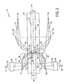
- Figure 2 shows a partial cross-section through a schematic representation of the device 30 for optical monitoring of the cigarette rod 28.
- the illustration of Figure 2 is only illustrative. The absolute and relative dimensions in Figure 2 therefore do not correspond to the actual dimensions. All the beam paths shown in Figure 2 and the light influencing elements are imaging beam paths or elements, i. E. Beam paths or elements of the geometric or ray optics whose mapping rules are known in the art.
- FIG. 2 shows the cigarette rod 28 in a horizontal course.
- the cigarette rod 28 has a strand center 44, the course of which coincides with the center 44 of a glass tube 46, in which the strand 28 moves.
- the glass tube 46 has no optical function, but only serves to guide the strand 28th
- the device 30 has a plurality of annularly around the strand 28 arranged around light sources 48.
- the light sources 48 respectively emit diverging optical beams 50 whose center beam 52 is substantially parallel to the center of the strand 44. For illustrative reasons, only two light sources 48 are shown.
- the device 30 furthermore has a reflective, curved surface 52 which lies in the path 52 of the optical beams 50 and acts as a first optical system arranged annularly around the strand 28.
- the annular structure of the surface 54 is in the figure 2 by perpendicular to the strand center 44 extending Dashed lines indicated the course of which is partially interrupted for illustrative reasons for the convergent beams 55
- the surface 54 is curved, positioned, and relative to and aligned with the light sources 48 for directing the diverging optical beams 50 from the midpoint beam direction 52, substantially parallel to the strand 28, to a steep angle to the strand direction 56 of the midpoint beam
- the radius of curvature of the surface 54 is such that, after being redirected through the surface 54, the redirected optical rays 55 are convergent until the strand center 44 is reached.
- the device 30 further comprises an optical polygon prism 64 formed as a second optic for redirecting the rays 62 reflected from the illuminated surface 60.
- the polygon prism 64 has a substantially cylindrical shape and has a central aperture along its major axis 44 coincident with the strand center 44 66 to accommodate the glass tube 46.
- the polygonal prism 64 thus lies with its inner surface 68 annularly around the glass tube 46 around.
- the annular structure of the prism 64 is indicated by dashed lines running perpendicular to the strand center 44, the course of which is partially interrupted for illustrative reasons for the reflected rays 62.
- the polygonal prism 64 has a truncated cone-shaped end 65 shown on the right in FIG.
- the frusto-conical end 65 creates in the polygonal prism 64 a conical inner surface 70 for guiding the reflected rays 62 circularly centered around and centered about the strand center 44, from an orientation 72 of the center ray perpendicular to the surface 58 of the strand 28 into one of the central axis substantially parallel to the strand center 44 extending orientation 74 of the center beam.
- the polygon prism 64 has an inclined flat inner surface 76 on the side shown in Figure 2 above the glass tube 46 and a mirror symmetry for this purpose to the strand center 44 arranged reflective, flat inclined inner surface 76 a.
- the inner surface 76 is oriented to reflect the portion of the optical beams of the center beam 74 above the beam center 44 in FIG Detector 81 generates focused optical beams 82. In a corresponding manner, the inner surface 76a directs the part of the optical beams of the central-point beam 74 below the middle of the line in FIG. 2 in a central beam direction 84 to a second imaging optical system 86 which generates optical beams 90 focused on a detector 88.
- the imaging optics 80 and 86 both have focusing lenses and apertures, not shown, for focusing the optical beams with the center beam beams 78 and 84, respectively.
- the function of the device 30 is as follows:
- the width 94 of the illuminated surface 60 increases due to the convergence of the rays 55 as the strand diameter 96 increases.
- the width 94 then increases in the region of the surface 58 of the strand 28 lying below the strand center 44 in FIG. 2, the width 94 decreases in the same way in FIG. 2 above the strand center 4 due to the convergence of the optical rays 55 lying area of the surface 58.
Landscapes
- Health & Medical Sciences (AREA)
- General Health & Medical Sciences (AREA)
- Analytical Chemistry (AREA)
- Physics & Mathematics (AREA)
- Life Sciences & Earth Sciences (AREA)
- Chemical & Material Sciences (AREA)
- Biochemistry (AREA)
- General Physics & Mathematics (AREA)
- Immunology (AREA)
- Pathology (AREA)
- Engineering & Computer Science (AREA)
- Textile Engineering (AREA)
- Toxicology (AREA)
- Manufacturing Of Cigar And Cigarette Tobacco (AREA)
Abstract
Description
- Die Erfindung betrifft eine Vorrichtung zur optischen Überwachung eines Materialstrangs der tabakverarbeitenden Industrie, insbesondere eines Zigarettenstrangs.
- Optische Prüfmittel der eingangs bezeichneten Gattung dienen zum Erfassen von Fehlern und Unregelmäßigkeiten an einem Materialstrang. Fehler in der Umhüllung eines bewegten Materialstrangs der tabakverarbeitenden Industrie, beispielsweise in der Papierumhüllung eines Zigarettenstrangs oder eines Filterstrangs, wie Löcher, Flecken, fehlende oder falsch platzierte Aufdrucke, lichtreflektierende Klebstellen usw., bewirken eine Änderung der Reflexion von auf die Hülle fallendem Licht. Löcher in der Umhüllung eines Zigarettenstrangs wirken beispielsweise wie dunkle Flecken und setzen den Reflexionsgrad herab. Aufdrucke verändern den Reflexionsgrad der Umhüllung je nach ihrem Farbton. Leimflecken außerhalb der Leimnaht erhöhen die Reflexion des Lichts an der Umhüllung des Zigarettenstrangs. So kann aus der Intensität des am bewegten Strang reflektierten Lichts auf den Zustand des Strangs geschlossen werden.
- Durch die
EP 1 518 469 A1 der Anmelderin ist eine Vorrichtung der eingangs genannten Art bekannt geworden. Diese Vorrichtung weist eine ringförmige Anordnung von parallel zur Strangrichtung strahlenden Lichtquellen auf, deren Licht durch eine erste Optik in der Form einer kegelförmigen Spiegelfläche nahezu senkrecht auf den Materialstrang umgeleitet wird, wobei das von dem Materialstrang reflektierte Licht von einer zweiten Optik in der Form einer zweiten kegelförmigen Spiegelfläche mit zu der ersten Spiegelfläche entgegengesetzter Neigung in eine parallel zum Strang verlaufende Richtung umgeleitet und von einer ringförmigen Anordnung von Detektoren erfasst wird. - Aufgabe der vorliegenden Erfindung ist es, Vorrichtungen der eingangs genannten Art zu verbessern.
- Diese Aufgabe wird erfindungsgemäß durch eine Vorrichtung gemäß Anspruch 1 gelöst.
- Die Erfindung umfasst die Erkenntnis, dass die aus dem Stand der Technik bekannten Vorrichtungen in bestimmten Fällen auch dann Fehler der eingangs genannten Art auf der Oberfläche des inspizierten Materialstrangs anzeigen, wenn derartige Fehler nicht vorhanden sind. Denn die bekannten Vorrichtungen reagieren auf die Intensität des am bewegten Strang reflektierten Lichts. Die Erfindung hat jedoch erkannt, dass derartige Änderungen der Intensität auch durch Schwankungen im Durchmesser des Materialstrangs und / oder durch Veränderungen der Position des Materialstrangs verursacht werden können. Denn die vorgenannten Änderungen bewirken eine Änderung der Menge des reflektierten Lichts, ohne das einer der eingangs genannten Fehler auf der Oberfläche des Materialstrangs vorhanden sein muss. Beispielsweise bewirkt eine Verringerung des Durchmessers des Materialstrangs eine Verringerung der auf dem Detektor abgebildeten Umfangsoberfläche des Materialstrangs. Dieser Effekt wird nur zum Teil dadurch kompensiert, dass durch die Verringerung des Umfangs des Materialstrangs und damit auch seiner Umfangsoberfläche die Beleuchtungsintensität zunimmt. Insgesamt gelangt weniger Licht auf den Detektor, wodurch der Vorrichtung suggeriert wird, dass an dieser Stelle ein Bereich verringerter Reflektion auf der Oberfläche des Materialstranges vorhanden ist.
- Zur Lösung derartiger Probleme wäre es beispielsweise möglich, die Toleranzbereiche der Messung so weit zu erhöhen, dass derartige Durchmesserschwankungen des Materialstrangs keine Auswirkung auf das Messergebnis mehr haben. Das würde jedoch die Genauigkeit der Messung entsprechend reduzieren. Eine solche Lösung ist daher nachteilig.
- Die Erfindung löst die geschilderten Probleme vorteilhaft dadurch, dass sie einen im Bereich der Oberfläche des zu inspizierenden Materialstrangs konvergenten Lichtstrahl zur Verfügung stellt- Auf diese Weise wird auch bei variierendem Strangdurchmesser und sich entsprechend veränderndem Umfang des Stranges immer die gleiche Lichtmenge auf den Bereich der Strangoberfläche geleitet, der auf dem Detektor abgebildet wird. Verringert sich beispielsweise der Strangumfang, so werden die beleuchtete Fläche und die auf dem Detektor abgebildete Fläche im gleichen Maße kleiner, so dass bei unveränderten Reflektionseigenschaften der Strangoberfläche die gleiche Lichtmenge auf den Detektor fällt. Vergrößert sich der Strangdurchmesser, so vergrößern sich die beleuchtete Fläche und die abgebildete Fläche in gleichem Maße, so dass die auf den Detektor gelangende Lichtmenge ebenfalls konstant bleibt
- Es ist daher dank der Erfindung möglich, die Oberfläche von Materialsträngen der tabakverarbeitenden Industrie zu inspizieren, ohne dass eine derartige Inspektion durch Durchmesserschwankungen oder Positionsänderungen des im Strahlkegel liegenden Materialstrangs beeinflusst wird.
- Wenn im hier in Rede stehenden Zusammenhang die Begriffe "Lichtstrahl" oder "optischer Strahl" verwendet werden, so bedeutet dies tatsächlich, dass ein Bündel von Lichtstahlen, auch Strahlenbündel genannt, vorliegt.
- Bevorzugte Ausführungsformen der Erfindung sind in den Unteransprüchen angegeben.
- Die erste Optik weist vorteilhaft eine gekrümmte reflektierende Fläche zum Umleiten der optischen Strahlen auf, wobei der Krümmungsradius der gekrümmten Fläche bevorzugt derart bemessen ist, dass sich eine Größe einer von den umgeleiteten optischen Strahlen auf der Oberfläche des Materialstrangs ausgeleuchteten Fläche sowie eine Größe einer auf dem Detektor abgebildeten Oberfläche des Materialstrangs bei einer Änderung der räumlichen Position der Oberfläche im wesentlichen im gleichen Maße ändern. Da hier alle Strahlengänge und das Licht beeinflussende Elemente abbildende Strahlengänge bzw. Elemente sind, d.h. Strahlengänge bzw. Elemente der geometrischen oder auch Strahlen-Optik sind, sind deren Abbildungsregeln dem Fachmann bekannt. Der Fachmann ist daher mit dieser Anweisung in der Lage, den Krümmungsradius in der zuvor geforderten Weise nach den Abbildungsregeln der geometrischen Optik auszubilden. Dabei kann der Krümmungsmittelpunkt der gekrümmten Fläche außerhalb der Mitte des Materialstrangs liegen.
- Bei einer bevorzugten Ausführungsform der Erfindung ist die vorgenannte gekrümmte Fläche eine zumindest teilweise geschlossen ringförmig um den Materialstrang herum angeordnete, bevorzugt auf die Mitte des Materialsstrangs zentrierte, Fläche zum Umleiten der optischen Strahlen der Lichtquellen. Auf diese Weise lässt sich der gesamte Umfang des Materialstrangs beleuchten und untersuchen.
- Mit Bezug auf die begleitenden Zeichnungen wird nun eine Ausführungsform der Erfindung beschrieben. Die Zeichnungen zeigen:
- Figur 1
- eine perspektivische Ansicht einer Zigarettenstrangmaschine; und
- Figur 2
- einen teilweisen Querschnitt durch eine schematische Darstellung einer Ausführungsform einer erfindungsgemäßen Vorrichtung zur optischen Überwachung eines Materialsstrangs der tabakverarbeitenden Industrie.
- Figur 1 zeigt eine perspektivische Ansicht einer Zigarettenstrangmaschine 50 der Anmelderin vom Typ Protos. Die Zigarettenstrangmaschine 50 funktioniert wie folgt: Von einer Schleuse 1 wird ein Vorverteiler 2 portionsweise mit Tabak beschickt. Eine Entnahmewalze 3 des Vorverteilers 2 ergänzt gesteuert einen Vorratsbehälter 4 mit Tabak, aus dem ein Steilförderer 5 Tabak entnimmt und einen Stauschacht 6 gesteuert beschickt. Aus dem Stauschacht 6 entnimmt eine Stiftwalze 7 einen gleichförmigen Tabakstrom, der von einer Ausschlagwalze 8 aus den Stiften der Stiftwalze 7 herausgeschlagen und auf ein mit konstanter Geschwindigkeit umlaufendes Streutuch 9 geschleudert wird. Ein auf dem Streutuch 9 gebildetes Tabakvlies wird in eine Sichteinrichtung 11 geschleudert, die im wesentlichen aus einem Luftvorhang besteht, den größere bzw. schwerere Tabakteile passieren, während alle anderen Tabakteilchen von der Luft in einen von einer Stiftwalze 12 und einer Wand 13 gebildeten Trichter 14 gelenkt werden. Von der Stiftwalze 12 wird der Tabak in einen Tabakkanal 16 gegen einen Strangförderer 17 geschleudert, an dem der Tabak mittels in eine Unterdruckkammer 18 gesaugter Luft gehalten und ein Tabakstrang aufgeschauert wird.
- Ein Egalisator 19 entfernt überschüssigen Tabak von dem Tabakstrang, der dann auf einen im Gleichlauf geführten Zigarettenpapierstreifen 21 gelegt wird. Der Zigarettenpapierstreifen 21 wird von einer Bobine 22 abgezogen, durch ein Druckwerk 23 geführt und auf ein angetriebenes Formatband 24 gelegt. Das Formatband 24 transportiert den Tabakstrang und den Zigarettenpapierstreifen 21 durch ein Format 26, in dem der Zigarettenpapierstreifen 21 um den Tabakstrang gefaltet wird, so dass noch eine Kante absteht, die von einem nicht dargestellten Leimapparat in bekannter Weise beleimt wird. Darauf wird die Klebnaht geschlossen und von einer Tandemnahtplätte 27 getrocknet.
- Ein so gebildeter Zigarettenstrang 28 durchläuft ein Strangdichtemessgerät 29, das den Egalisator 19 steuert, und eine Ausführungsform 30 einer erfindungsgemäßen Vorrichtung 30 zur optischen Überwachung des Zigarettenstrangs 28, welcher anschließend von einem Messerapparat 31 in doppeltlange Zigaretten 32 geschnitten wird. Die doppeltlangen Zigaretten 32 werden von einer gesteuerte Arme 33 aufweisenden Übergabevorrichtung 34 einer Übernahmetrommel 36 einer Filteransetzmaschine 37 übergeben, auf deren Schneidtrommel 38 sie mit einem Kreismesser in Einzelzigaretten geteilt werden.
- Förderbänder 39, 41 fördern überschüssigen Tabak in einen unter dem Vorratsbehälter 4 angeordneten Behälter 42, aus dem der rückgeführte Tabak von dem Steilförderer 5 wieder entnommen wird.
- Figur 2 zeigt einen teilweisen Querschnitt durch eine schematische Darstellung der Vorrichtung 30 zur optischen Überwachung des Zigarettenstrangs 28. Die Darstellung der Figur 2 dient nur der Verdeutlichung. Die absoluten und relativen Abmessungen in der Figur 2 entsprechen daher nicht den tatsächlichen Abmessungen. Alle in der Figur 2 dargestellten Strahlengänge und das Licht beeinflussende Elemente sind abbildende Strahlengänge bzw. Elemente, d.h. Strahlengänge bzw. Elemente der geometrischen oder auch Strahlen-Optik, deren Abbildungsregeln dem Fachmann bekannt sind.
- Figur 2 stellt den Zigarettenstrang 28 in einem horizontalen Verlauf dar. Der Zigarettenstrang 28 weist eine Strangmitte 44 auf, deren Verlauf mit der Mitte 44 eines Glasröhrchens 46 übereinstimmt, in dem sich der Strang 28 bewegt. Das Glasröhrchen 46 hat keine optische Funktion, sondern dient nur der Führung des Stranges 28.
- Die Vorrichtung 30 weist mehrere, ringförmig um den Strang 28 herum angeordnete Lichtquellen 48 auf. Die Lichtquellen 48 geben jeweils divergierende optische Strahlen 50 ab, deren Mittelpunktsstrahle 52 im wesentlichen parallel zur Strangmitte 44 verlaufen. Aus zeichnerischen Gründen sind nur zwei Lichtquellen 48 dargestellt.
- Die Vorrichtung 30 weist weiterhin eine als erste Optik dienende, ringförmig um den Strang 28 herum angeordnete reflektierende, gekrümmte, im Verlauf 52 der optischen Strahlen 50 liegende Oberfläche 54 auf. Die ringförmige Struktur der Oberfläche 54 ist in der Figur 2 durch senkrecht zur Strangmitte 44 verlaufende gestrichelte Linien angedeutet, deren Verlauf aus zeichnerischen Gründen für die konvergenten Strahlen 55 teilweise unterbrochen ist
- Die Oberfläche 54 ist derart gekrümmt, positioniert und relativ und zu den Lichtquellen 48 ausgerichtet, dass sie die divergierenden optischen Strahlen 50 aus der im Wesentlichen parallel zum Strang 28 verlaufenden Richtung 52 des Mittelpunktsstrahls in eine in einem steilen Winkel zum Strang verlaufende Richtung 56 des Mittelpunktsstrahls umleitet und auf die Strangmitte 44 fokussiert Der Krümmungsradius der Fläche 54 ist mit anderen Worten derart, dass nach dem Umleiten durch die Fläche 54 die umgeleiteten optischen Strahlen 55 bis zum Erreichen der Strangmitte 44 konvergent sind.
- Die Vorrichtung 30 umfasst weiterhin ein als eine zweite Optik zum Umleiten der von der beleuchteten Fläche 60 reflektierten Strahlen 62 ausgebildetes optisches Polygonprisma 64. Das Polygonprisma 64 weist eine im wesentlichen zylindrische Form auf und weist entlang seiner mit der Strangmitte 44 zusammenfallenden Hauptachse 44 einen zentralen Durchbruch 66 auf, um das Glasröhrchen 46 aufzunehmen. Das Polygonprisma 64 liegt somit mit seiner Innenoberfläche 68 ringförmig um das Glasröhrchen 46 herum. Auch hier ist die ringförmige Struktur des Prismas 64 durch senkrecht zur Strangmitte 44 verlaufende gestrichelte Linien angedeutet, deren Verlauf aus zeichnerischen Gründen für die reflektierten Strahlen 62 teilweise unterbrochen ist.
- Das Polygonprisma 64 weist ein in der Figur 2 rechts dargestelltes kegelstumpfartiges Ende 65 auf. Das kegelstumpfartige Ende 65 erzeugt in dem Polygonprisma 64 eine konische, kreisförmig um die Strangmitte 44 herum angeordnete und auf diese zentrierte, reflektierende Innenoberfläche 70 zum Umleiten der reflektierten Strahlen 62 aus einer steil zur Oberfläche 58 des Strangs 28 verlaufenden Ausrichtung 72 des Mittelpunktsstrahls in eine im wesentlichen parallel zur Strangmitte 44 verlaufende Ausrichtung 74 des Mittelpunktsstrahls.
- Das Polygonprisma 64 weist eine geneigte flache Innenoberfläche 76 auf der in Figur 2 oberhalb des Glasröhrchens 46 dargestellten Seite und eine hierzu spiegelsymmetrisch zur Strangmitte 44 angeordnete reflektierende, flache geneigte Innenoberfläche 76a auf.
- Die Innenoberfläche 76 ist so ausgerichtet, dass sie den in der Figur 2 oberhalb der Strangmitte 44 liegenden Teil der optischen Strahlen des Mittelpunktsstrahls 74 in eine im wesentlichen wieder senkrecht zur Strangmitte 44 verlaufende Richtung 78 des Mittelpunktsstrahls auf eine Abbildungsoptik 80 reflektiert, die schließlich auf einen Detektor 81 fokussierte optische Strahlen 82 erzeugt. In entsprechender Weise leitet die Innenoberfläche 76a den in der Figur 2 unterhalb der Strangmitte 44 liegenden Teil der optischen Strahlen des Mittelpunkisstrahls 74 in eine mittlere Strahlrichtung 84 auf eine zweite Abbildungsoptik 86, die auf einen Detektor 88 fokussierte optische Strahlen 90 erzeugt. Die Abbildungsoptiken 80 und 86 weisen beide jeweils nicht dargestellte Fokussierlinsen und Blenden zum Fokussieren der optischen Strahlen mit den Mittelpunktsstrahlen 78 bzw. 84 auf.
- Die Funktion der Vorrichtung 30 ist wie folgt:
- Aufgrund der Konvergenz der von der gekrümmten Fläche 54 reflektierten, entlang der optischen Achse 56 verlaufenden Strahlen 55 wird von diesen auf der Oberfläche 58 des Zigarettenstrangs 28 eine in der Figur 2 schematisch angedeutete Umfangsoberfläche 60 des Zigarettenstrangs 28 ausgeleuchtet. Durch die nach dem Hindurchtreten durch das Glasröhrchen 46 weiter bestehende Konvergenz der Strahlen 55 verringert sich die Breite 94 der beleuchteten Fläche 60, wenn sich der Durchmesser 96 des Strangs 28 verringert. Auf diese Weise wird die Verringerung der auf dem Detektor 81 abgebildeten Fläche durch die Erhöhung der Beleuchtungsintensität weitgehend kompensiert.
- In entsprechender Art und Weise vergrößert sich die Breite 94 der beleuchteten Fläche 60 durch die Konvergenz der Strahlen 55, wenn sich der Strangdurchmesser 96 vergrößert.
- Ähnliches gilt, wenn sich die Strangmitte 44 relativ zum Glasröhrchen 46 beispielsweise in der Figur 2 nach unten verschiebt. Dann vergrößert sich zwar die Breite 94 in dem in der Figur 2 unterhalb der Strangmitte 44 liegenden Bereich der Oberfläche 58 des Strangs 28. Genauso verkleinert sich jedoch aufgrund der Konvergenz der optischen Strahlen 55 die Breite 94 in dem in der Figur 2 oberhalb der Strangmitte 4 liegenden Bereich der Oberfläche 58.
Claims (11)
- Vorrichtung zur optischen Überwachung eines Materialstrangs (28) der tabakverarbeitenden Industrie, insbesondere eines Zigarettenstrangs (28), mit:einer ersten Optik (54) zum Umleiten von im wesentlichen parallel zum Materialstrang (28) zur Verfügung gestellten optischen Strahlen (50) in Richtung auf den Materialstrang (28), undeinem Detektor (81, 88) zum Detektieren der von dem Materialstrang (28) reflektierten Strahlen (55),dadurch gekennzeichnet, dass die erste Optik (54) derart ausgebildet ist, dass von der Optik (54) umgeleitete optische Strahlen (55) im Bereich der Oberfläche (58) des Materialstrangs (28) Konvergenz aufweisen.
- Vorrichtung nach Anspruch 1,
wobei die Konvergenz derart ist, dass eine Lichtmenge der umgeleiteten optischen Strahlen (55), mit der eine Fläche (60) auf der Oberfläche (58) des Materialstrangs (28) ausgeleuchtet wird, die vom Detektor (81, 88) abgebildet wird, auch bei einer Änderung der räumlichen Position der Oberfläche (58) im wesentlichen unverändert bleibt. - Vorrichtung nach einem der vorstehenden Ansprüche,
wobei die erste Optik (54) eine gekrümmte reflektierende Fläche (54) zum Umleiten der optischen Strahlen (50) aufweist. - Vorrichtung nach Anspruch 3,
wobei der Krümmungsradius der gekrümmten Fläche (54) derart bemessen ist, dass eine Lichtmenge der umgeleiteten optischen Strahlen (55), mit der eine Fläche (60) auf der Oberfläche (58) des Materialstrangs (28) ausgeleuchtet wird, die vom Detektor (81, 88) abgebildet wird, auch bei einer Änderung der räumlichen Position der Oberfläche (58) im wesentlichen unverändert bleibt. - Vorrichtung nach einem der Ansprüche 4 oder 5,
wobei der Krümmungsmittelpunkt der gekrümmten Fläche (54) außerhalb der Mitte (44) des Materialstrangs (28) liegt. - Vorrichtung nach einem der vorstehenden Ansprüche,
wobei die erste Optik (54) eine zumindest teilweise geschlossen ringförmig um den Materialstrang (28) herum angeordnete, bevorzugt auf die Mitte (44) des Materialsstrangs (28) zentrierte, reflektierende Fläche (54) zum - Umleiten der optischen Strahlen (50) aufweist. - Vorrichtung nach einem der vorstehenden Ansprüche,
mit mindestens einer Lichtquelle (48), um jeweils einen divergierenden optischen Strahl (50) zur Verfügung zu stellen. - Vorrichtung nach Anspruch 7,
mit mindestens drei Lichtquellen (48), wobei die Lichtquellen (48) ringförmig um den Materialstrang (28) herum, bevorzugt auf die Mitte (44) des Materialsstrangs (28) zentriert, angeordnet sind. - Vorrichtung nach einem der vorstehenden Ansprüche,
mit einer zweiten Optik (64) zum Umleiten der von dem Materialstrang (28) reflektierten Strahlen (62) auf den Detektor (81, 88). - Vorrichtung nach Anspruch 9,
wobei die zweite Optik (64) einen prismatischen reflektierenden Körper (64), insbesondere ein Polygonprisma (64), umfasst. - Vorrichtung nach einem der vorstehenden Ansprüche,
wobei zwischen Reflektion und Detektion des optischen Strahls (50, 55) eine, bevorzugt eine Fokussierlinse und / oder eine Blende umfassende, Abbildungsoptik (80, 86) vorgesehen ist.
Priority Applications (1)
| Application Number | Priority Date | Filing Date | Title |
|---|---|---|---|
| PL06023046T PL1782703T3 (pl) | 2005-11-08 | 2006-11-06 | Urządzenie do kontroli optycznej kabla materiałowego w przemyśle tytoniowym |
Applications Claiming Priority (1)
| Application Number | Priority Date | Filing Date | Title |
|---|---|---|---|
| DE102005053537A DE102005053537A1 (de) | 2005-11-08 | 2005-11-08 | Vorrichtung zur optischen Überwachung eines Materialstranges der tabakverarbeitenden Industrie |
Publications (2)
| Publication Number | Publication Date |
|---|---|
| EP1782703A1 true EP1782703A1 (de) | 2007-05-09 |
| EP1782703B1 EP1782703B1 (de) | 2016-01-20 |
Family
ID=37762312
Family Applications (1)
| Application Number | Title | Priority Date | Filing Date |
|---|---|---|---|
| EP06023046.3A Active EP1782703B1 (de) | 2005-11-08 | 2006-11-06 | Vorrichtung zur optischen Überwachung eines Materialstranges der tabakverarbeitenden Industrie |
Country Status (4)
| Country | Link |
|---|---|
| EP (1) | EP1782703B1 (de) |
| CN (1) | CN100574653C (de) |
| DE (1) | DE102005053537A1 (de) |
| PL (1) | PL1782703T3 (de) |
Cited By (3)
| Publication number | Priority date | Publication date | Assignee | Title |
|---|---|---|---|---|
| DE102009016499A1 (de) | 2009-04-08 | 2010-10-21 | Hauni Maschinenbau Ag | Verfahren zur optischen Kontrolle eines Umhüllungspapierstreifens der Tabak verarbeitenden Industrie |
| EP2684472A2 (de) | 2012-07-10 | 2014-01-15 | HAUNI Maschinenbau AG | Verfahren zum Steuern einer Maschinenkombination und/oder einer Maschine zur Verarbeitung von stabförmigen Artikeln der Tabak verarbeitenden Industrie sowie eine Maschinenvorrichtung dafür |
| EP2641481B1 (de) | 2012-03-19 | 2016-05-11 | HAUNI Maschinenbau AG | Filterstabherstellmaschine und Verfahren zum Betrieb einer Filterstabherstellmaschine der Tabak verarbeitenden Industrie |
Families Citing this family (3)
| Publication number | Priority date | Publication date | Assignee | Title |
|---|---|---|---|---|
| CN101893581B (zh) * | 2010-07-26 | 2012-09-19 | 深圳市华德防伪技术开发有限公司 | 一种香烟拉线防伪检测仪 |
| CN102697176A (zh) * | 2012-06-23 | 2012-10-03 | 常德烟草机械有限责任公司 | 一种基于机器视觉的烟支质量在线检测装置及检测方法 |
| DE102021111517A1 (de) * | 2021-05-04 | 2022-11-10 | H & T Marsberg Gmbh & Co. Kg | Inspektionsvorrichtung zur Inspektion von zylindrischen Metallformteilen |
Citations (3)
| Publication number | Priority date | Publication date | Assignee | Title |
|---|---|---|---|---|
| GB2060348A (en) * | 1979-10-05 | 1981-05-07 | Hauni Werke Koerber & Co Kg | Apparatus for monitoring the exterior of a moving cigarette rod or the like |
| DE3418079A1 (de) * | 1983-05-31 | 1984-12-06 | Hauni-Werke Körber & Co KG, 2050 Hamburg | Vorrichtung zum optischen abtasten der oberflaeche eines bewegten zigarettenstrangs |
| DE19713973A1 (de) * | 1997-04-04 | 1998-10-15 | Fraunhofer Ges Forschung | Verfahren und Vorrichtung zum optischen Prüfen der Mantelfläche zylindrischer Körper |
Family Cites Families (4)
| Publication number | Priority date | Publication date | Assignee | Title |
|---|---|---|---|---|
| JP3099462B2 (ja) | 1991-09-30 | 2000-10-16 | 凸版印刷株式会社 | 円筒面検査方法及びその装置 |
| DE10229188A1 (de) | 2002-06-28 | 2004-01-29 | Infineon Technologies Ag | Verfahren zur Herstellung von Kontakten zu Teilen eines in einem Halbleitersubstrat integrierten Bauelementes |
| EP1518469B1 (de) * | 2003-09-24 | 2006-10-04 | Hauni Maschinenbau Aktiengesellschaft | Verfahren und Vorrichtung zur Überwachung eines Materialstrangs der tabakverarbeitenden Industrie |
| CN102697176A (zh) * | 2012-06-23 | 2012-10-03 | 常德烟草机械有限责任公司 | 一种基于机器视觉的烟支质量在线检测装置及检测方法 |
-
2005
- 2005-11-08 DE DE102005053537A patent/DE102005053537A1/de not_active Ceased
-
2006
- 2006-11-06 EP EP06023046.3A patent/EP1782703B1/de active Active
- 2006-11-06 PL PL06023046T patent/PL1782703T3/pl unknown
- 2006-11-08 CN CN200610143699A patent/CN100574653C/zh active Active
Patent Citations (3)
| Publication number | Priority date | Publication date | Assignee | Title |
|---|---|---|---|---|
| GB2060348A (en) * | 1979-10-05 | 1981-05-07 | Hauni Werke Koerber & Co Kg | Apparatus for monitoring the exterior of a moving cigarette rod or the like |
| DE3418079A1 (de) * | 1983-05-31 | 1984-12-06 | Hauni-Werke Körber & Co KG, 2050 Hamburg | Vorrichtung zum optischen abtasten der oberflaeche eines bewegten zigarettenstrangs |
| DE19713973A1 (de) * | 1997-04-04 | 1998-10-15 | Fraunhofer Ges Forschung | Verfahren und Vorrichtung zum optischen Prüfen der Mantelfläche zylindrischer Körper |
Cited By (4)
| Publication number | Priority date | Publication date | Assignee | Title |
|---|---|---|---|---|
| DE102009016499A1 (de) | 2009-04-08 | 2010-10-21 | Hauni Maschinenbau Ag | Verfahren zur optischen Kontrolle eines Umhüllungspapierstreifens der Tabak verarbeitenden Industrie |
| EP2641481B1 (de) | 2012-03-19 | 2016-05-11 | HAUNI Maschinenbau AG | Filterstabherstellmaschine und Verfahren zum Betrieb einer Filterstabherstellmaschine der Tabak verarbeitenden Industrie |
| EP2684472A2 (de) | 2012-07-10 | 2014-01-15 | HAUNI Maschinenbau AG | Verfahren zum Steuern einer Maschinenkombination und/oder einer Maschine zur Verarbeitung von stabförmigen Artikeln der Tabak verarbeitenden Industrie sowie eine Maschinenvorrichtung dafür |
| DE102012106180A1 (de) | 2012-07-10 | 2014-01-16 | Hauni Maschinenbau Ag | Verfahren zum Steuern einer Maschinenkombination und/oder einer Maschine zur Verarbeitung von stabförmigen Artikeln der Tabak verarbeitenden Industrie sowie eine Maschinenvorrichtung dafür |
Also Published As
| Publication number | Publication date |
|---|---|
| EP1782703B1 (de) | 2016-01-20 |
| DE102005053537A1 (de) | 2007-05-16 |
| CN100574653C (zh) | 2009-12-30 |
| CN1961764A (zh) | 2007-05-16 |
| PL1782703T3 (pl) | 2016-06-30 |
Similar Documents
| Publication | Publication Date | Title |
|---|---|---|
| DE3437580C2 (de) | Vorrichtung zum optischen Prüfen eines Zigarettenstrangs | |
| EP0279191B1 (de) | Gerät zur berührungslosen Remissionsmessung | |
| EP2918180B2 (de) | Optische Prüfung von stabförmigen Artikeln der Tabak verarbeitenden Industrie | |
| EP0431406B1 (de) | Vorrichtung zum Beleuchten eines zu prüfenden Bereiches einer Flasche | |
| DE3624236A1 (de) | Verfahren und vorrichtung zum pruefen der dichte eines umhuellten tabakstrangs | |
| DE2433683C3 (de) | Vorrichtung zur Überwachung einer Materialbahn auf Fehlstellen | |
| EP0873510A2 (de) | Inspektionsvorrichtung für flaschen oder dgl. | |
| DE102004057092A1 (de) | Messen des Durchmessers von stabförmigen Artikeln der Tabak verarbeitenden Industrie | |
| EP0650915A1 (de) | Vorrichtung zur Überprüfung der Wickelqualität von Garnspulen und Verwendung der Vorrichtung an einer Spul- oder Spinnmaschine | |
| DE3418674C2 (de) | Verfahren und Vorichtung zum Abtasten eines stabförmigen Artikels der tabakverarbeitenden Industrie | |
| DE4211985A1 (de) | Spulenpruefvorrichtung | |
| DE19523741C2 (de) | Optische Detektoreinrichtung für eine strömende Probe | |
| DE2626275A1 (de) | Geraet zum automatischen pruefen von achssymmetrischen werkstueckprofilen | |
| EP1826557B2 (de) | Optische Kontrolle von Produkten der Tabak verarbeitenden Industrie | |
| EP1782703B1 (de) | Vorrichtung zur optischen Überwachung eines Materialstranges der tabakverarbeitenden Industrie | |
| DE2653298A1 (de) | Pruefvorrichtung zum pruefen der enden von zigaretten | |
| DE69735401T2 (de) | Verfahren zur Messung der Intensität eines einen Körper durchdringenden Strahlungsbündels | |
| CH402461A (de) | Elektro-optischer Fadenreiniger | |
| DE202009012142U1 (de) | Optoelektronischer Sensor zur Streifenerkennung | |
| DE10323152A1 (de) | Vorrichtung zum Messen des Durchmessers eines stabförmigen Gegenstandes insbesondere der Tabak verarbeitenden Industrie | |
| EP1518469B1 (de) | Verfahren und Vorrichtung zur Überwachung eines Materialstrangs der tabakverarbeitenden Industrie | |
| DE3420470A1 (de) | Optische pruefvorrichtung fuer zigaretten | |
| DE3418079A1 (de) | Vorrichtung zum optischen abtasten der oberflaeche eines bewegten zigarettenstrangs | |
| DE19726967C1 (de) | Vorrichtung zum optischen Abbilden der umlaufenden Seitenfläche eines Gegenstandes, insbesondere eines 0-Rings | |
| DE10160235A1 (de) | Verfahren und Vorrichtung zur Erfassung einer Eigenschaft von Zigarettenpapier |
Legal Events
| Date | Code | Title | Description |
|---|---|---|---|
| PUAI | Public reference made under article 153(3) epc to a published international application that has entered the european phase |
Free format text: ORIGINAL CODE: 0009012 |
|
| AK | Designated contracting states |
Kind code of ref document: A1 Designated state(s): AT BE BG CH CY CZ DE DK EE ES FI FR GB GR HU IE IS IT LI LT LU LV MC NL PL PT RO SE SI SK TR |
|
| AX | Request for extension of the european patent |
Extension state: AL BA HR MK YU |
|
| 17P | Request for examination filed |
Effective date: 20071109 |
|
| 17Q | First examination report despatched |
Effective date: 20071213 |
|
| AKX | Designation fees paid |
Designated state(s): AT BE BG CH CY CZ DE DK EE ES FI FR GB GR HU IE IS IT LI LT LU LV MC NL PL PT RO SE SI SK TR |
|
| GRAP | Despatch of communication of intention to grant a patent |
Free format text: ORIGINAL CODE: EPIDOSNIGR1 |
|
| INTG | Intention to grant announced |
Effective date: 20150814 |
|
| RIC1 | Information provided on ipc code assigned before grant |
Ipc: G01N 21/952 20060101ALI20150731BHEP Ipc: A24C 5/34 20060101AFI20150731BHEP |
|
| GRAS | Grant fee paid |
Free format text: ORIGINAL CODE: EPIDOSNIGR3 |
|
| GRAA | (expected) grant |
Free format text: ORIGINAL CODE: 0009210 |
|
| AK | Designated contracting states |
Kind code of ref document: B1 Designated state(s): AT BE BG CH CY CZ DE DK EE ES FI FR GB GR HU IE IS IT LI LT LU LV MC NL PL PT RO SE SI SK TR |
|
| REG | Reference to a national code |
Ref country code: GB Ref legal event code: FG4D Free format text: NOT ENGLISH |
|
| REG | Reference to a national code |
Ref country code: DE Ref legal event code: R081 Ref document number: 502006014726 Country of ref document: DE Owner name: HAUNI MASCHINENBAU GMBH, DE Free format text: FORMER OWNER: HAUNI MASCHINENBAU AG, 21033 HAMBURG, DE |
|
| REG | Reference to a national code |
Ref country code: CH Ref legal event code: EP |
|
| REG | Reference to a national code |
Ref country code: IE Ref legal event code: FG4D Free format text: LANGUAGE OF EP DOCUMENT: GERMAN |
|
| REG | Reference to a national code |
Ref country code: AT Ref legal event code: REF Ref document number: 771292 Country of ref document: AT Kind code of ref document: T Effective date: 20160215 |
|
| REG | Reference to a national code |
Ref country code: DE Ref legal event code: R096 Ref document number: 502006014726 Country of ref document: DE |
|
| REG | Reference to a national code |
Ref country code: LT Ref legal event code: MG4D |
|
| REG | Reference to a national code |
Ref country code: NL Ref legal event code: MP Effective date: 20160120 |
|
| REG | Reference to a national code |
Ref country code: NL Ref legal event code: FP |
|
| RAP2 | Party data changed (patent owner data changed or rights of a patent transferred) |
Owner name: HAUNI MASCHINENBAU GMBH |
|
| REG | Reference to a national code |
Ref country code: DE Ref legal event code: R081 Ref document number: 502006014726 Country of ref document: DE Owner name: HAUNI MASCHINENBAU GMBH, DE Free format text: FORMER OWNER: HAUNI MASCHINENBAU AG, 21033 HAMBURG, DE |
|
| PG25 | Lapsed in a contracting state [announced via postgrant information from national office to epo] |
Ref country code: FI Free format text: LAPSE BECAUSE OF FAILURE TO SUBMIT A TRANSLATION OF THE DESCRIPTION OR TO PAY THE FEE WITHIN THE PRESCRIBED TIME-LIMIT Effective date: 20160120 Ref country code: GR Free format text: LAPSE BECAUSE OF FAILURE TO SUBMIT A TRANSLATION OF THE DESCRIPTION OR TO PAY THE FEE WITHIN THE PRESCRIBED TIME-LIMIT Effective date: 20160421 Ref country code: ES Free format text: LAPSE BECAUSE OF FAILURE TO SUBMIT A TRANSLATION OF THE DESCRIPTION OR TO PAY THE FEE WITHIN THE PRESCRIBED TIME-LIMIT Effective date: 20160120 |
|
| PG25 | Lapsed in a contracting state [announced via postgrant information from national office to epo] |
Ref country code: IS Free format text: LAPSE BECAUSE OF FAILURE TO SUBMIT A TRANSLATION OF THE DESCRIPTION OR TO PAY THE FEE WITHIN THE PRESCRIBED TIME-LIMIT Effective date: 20160520 Ref country code: LT Free format text: LAPSE BECAUSE OF FAILURE TO SUBMIT A TRANSLATION OF THE DESCRIPTION OR TO PAY THE FEE WITHIN THE PRESCRIBED TIME-LIMIT Effective date: 20160120 Ref country code: PT Free format text: LAPSE BECAUSE OF FAILURE TO SUBMIT A TRANSLATION OF THE DESCRIPTION OR TO PAY THE FEE WITHIN THE PRESCRIBED TIME-LIMIT Effective date: 20160520 Ref country code: SE Free format text: LAPSE BECAUSE OF FAILURE TO SUBMIT A TRANSLATION OF THE DESCRIPTION OR TO PAY THE FEE WITHIN THE PRESCRIBED TIME-LIMIT Effective date: 20160120 Ref country code: LV Free format text: LAPSE BECAUSE OF FAILURE TO SUBMIT A TRANSLATION OF THE DESCRIPTION OR TO PAY THE FEE WITHIN THE PRESCRIBED TIME-LIMIT Effective date: 20160120 |
|
| REG | Reference to a national code |
Ref country code: DE Ref legal event code: R026 Ref document number: 502006014726 Country of ref document: DE |
|
| PLBI | Opposition filed |
Free format text: ORIGINAL CODE: 0009260 |
|
| PG25 | Lapsed in a contracting state [announced via postgrant information from national office to epo] |
Ref country code: EE Free format text: LAPSE BECAUSE OF FAILURE TO SUBMIT A TRANSLATION OF THE DESCRIPTION OR TO PAY THE FEE WITHIN THE PRESCRIBED TIME-LIMIT Effective date: 20160120 Ref country code: DK Free format text: LAPSE BECAUSE OF FAILURE TO SUBMIT A TRANSLATION OF THE DESCRIPTION OR TO PAY THE FEE WITHIN THE PRESCRIBED TIME-LIMIT Effective date: 20160120 |
|
| REG | Reference to a national code |
Ref country code: NL Ref legal event code: PD Owner name: HAUNI MASCHINENBAU GMBH; DE Free format text: DETAILS ASSIGNMENT: VERANDERING VAN EIGENAAR(S), VERANDERING VAN DE JURIDISCHE ENTITEIT; FORMER OWNER NAME: HAUNI MASCHINENBAU AKTIENGESELLSCHAFT Effective date: 20161007 |
|
| PLAX | Notice of opposition and request to file observation + time limit sent |
Free format text: ORIGINAL CODE: EPIDOSNOBS2 |
|
| 26 | Opposition filed |
Opponent name: G.D S.P.A. Effective date: 20161019 |
|
| PG25 | Lapsed in a contracting state [announced via postgrant information from national office to epo] |
Ref country code: RO Free format text: LAPSE BECAUSE OF FAILURE TO SUBMIT A TRANSLATION OF THE DESCRIPTION OR TO PAY THE FEE WITHIN THE PRESCRIBED TIME-LIMIT Effective date: 20160120 Ref country code: CZ Free format text: LAPSE BECAUSE OF FAILURE TO SUBMIT A TRANSLATION OF THE DESCRIPTION OR TO PAY THE FEE WITHIN THE PRESCRIBED TIME-LIMIT Effective date: 20160120 Ref country code: SK Free format text: LAPSE BECAUSE OF FAILURE TO SUBMIT A TRANSLATION OF THE DESCRIPTION OR TO PAY THE FEE WITHIN THE PRESCRIBED TIME-LIMIT Effective date: 20160120 |
|
| PG25 | Lapsed in a contracting state [announced via postgrant information from national office to epo] |
Ref country code: BE Free format text: LAPSE BECAUSE OF NON-PAYMENT OF DUE FEES Effective date: 20161130 Ref country code: BG Free format text: LAPSE BECAUSE OF FAILURE TO SUBMIT A TRANSLATION OF THE DESCRIPTION OR TO PAY THE FEE WITHIN THE PRESCRIBED TIME-LIMIT Effective date: 20160420 Ref country code: SI Free format text: LAPSE BECAUSE OF FAILURE TO SUBMIT A TRANSLATION OF THE DESCRIPTION OR TO PAY THE FEE WITHIN THE PRESCRIBED TIME-LIMIT Effective date: 20160120 |
|
| PLBB | Reply of patent proprietor to notice(s) of opposition received |
Free format text: ORIGINAL CODE: EPIDOSNOBS3 |
|
| REG | Reference to a national code |
Ref country code: CH Ref legal event code: PL |
|
| PG25 | Lapsed in a contracting state [announced via postgrant information from national office to epo] |
Ref country code: CH Free format text: LAPSE BECAUSE OF NON-PAYMENT OF DUE FEES Effective date: 20161130 Ref country code: LI Free format text: LAPSE BECAUSE OF NON-PAYMENT OF DUE FEES Effective date: 20161130 |
|
| REG | Reference to a national code |
Ref country code: IE Ref legal event code: MM4A |
|
| REG | Reference to a national code |
Ref country code: FR Ref legal event code: ST Effective date: 20170731 |
|
| PG25 | Lapsed in a contracting state [announced via postgrant information from national office to epo] |
Ref country code: LU Free format text: LAPSE BECAUSE OF NON-PAYMENT OF DUE FEES Effective date: 20161130 |
|
| PG25 | Lapsed in a contracting state [announced via postgrant information from national office to epo] |
Ref country code: FR Free format text: LAPSE BECAUSE OF NON-PAYMENT OF DUE FEES Effective date: 20161130 |
|
| PG25 | Lapsed in a contracting state [announced via postgrant information from national office to epo] |
Ref country code: IE Free format text: LAPSE BECAUSE OF NON-PAYMENT OF DUE FEES Effective date: 20161106 |
|
| REG | Reference to a national code |
Ref country code: AT Ref legal event code: MM01 Ref document number: 771292 Country of ref document: AT Kind code of ref document: T Effective date: 20161106 |
|
| PG25 | Lapsed in a contracting state [announced via postgrant information from national office to epo] |
Ref country code: AT Free format text: LAPSE BECAUSE OF NON-PAYMENT OF DUE FEES Effective date: 20161106 |
|
| REG | Reference to a national code |
Ref country code: BE Ref legal event code: MM Effective date: 20161130 |
|
| PLCK | Communication despatched that opposition was rejected |
Free format text: ORIGINAL CODE: EPIDOSNREJ1 |
|
| REG | Reference to a national code |
Ref country code: DE Ref legal event code: R100 Ref document number: 502006014726 Country of ref document: DE |
|
| PLBN | Opposition rejected |
Free format text: ORIGINAL CODE: 0009273 |
|
| STAA | Information on the status of an ep patent application or granted ep patent |
Free format text: STATUS: OPPOSITION REJECTED |
|
| PG25 | Lapsed in a contracting state [announced via postgrant information from national office to epo] |
Ref country code: HU Free format text: LAPSE BECAUSE OF FAILURE TO SUBMIT A TRANSLATION OF THE DESCRIPTION OR TO PAY THE FEE WITHIN THE PRESCRIBED TIME-LIMIT; INVALID AB INITIO Effective date: 20061106 Ref country code: CY Free format text: LAPSE BECAUSE OF FAILURE TO SUBMIT A TRANSLATION OF THE DESCRIPTION OR TO PAY THE FEE WITHIN THE PRESCRIBED TIME-LIMIT Effective date: 20160120 |
|
| 27O | Opposition rejected |
Effective date: 20180217 |
|
| PG25 | Lapsed in a contracting state [announced via postgrant information from national office to epo] |
Ref country code: TR Free format text: LAPSE BECAUSE OF FAILURE TO SUBMIT A TRANSLATION OF THE DESCRIPTION OR TO PAY THE FEE WITHIN THE PRESCRIBED TIME-LIMIT Effective date: 20160120 Ref country code: MC Free format text: LAPSE BECAUSE OF FAILURE TO SUBMIT A TRANSLATION OF THE DESCRIPTION OR TO PAY THE FEE WITHIN THE PRESCRIBED TIME-LIMIT Effective date: 20160120 |
|
| REG | Reference to a national code |
Ref country code: DE Ref legal event code: R081 Ref document number: 502006014726 Country of ref document: DE Owner name: KOERBER TECHNOLOGIES GMBH, DE Free format text: FORMER OWNER: HAUNI MASCHINENBAU GMBH, 21033 HAMBURG, DE |
|
| REG | Reference to a national code |
Ref country code: NL Ref legal event code: HC Owner name: KOERBER TECHNOLOGIES GMBH; DE Free format text: DETAILS ASSIGNMENT: CHANGE OF OWNER(S), CHANGE OF OWNER(S) NAME; FORMER OWNER NAME: HAUNI MASCHINENBAU GMBH Effective date: 20221031 |
|
| P01 | Opt-out of the competence of the unified patent court (upc) registered |
Effective date: 20230621 |
|
| PGFP | Annual fee paid to national office [announced via postgrant information from national office to epo] |
Ref country code: NL Payment date: 20241128 Year of fee payment: 19 |
|
| PGFP | Annual fee paid to national office [announced via postgrant information from national office to epo] |
Ref country code: DE Payment date: 20241209 Year of fee payment: 19 |
|
| PGFP | Annual fee paid to national office [announced via postgrant information from national office to epo] |
Ref country code: PL Payment date: 20241022 Year of fee payment: 19 |
|
| PGFP | Annual fee paid to national office [announced via postgrant information from national office to epo] |
Ref country code: GB Payment date: 20241127 Year of fee payment: 19 |
|
| PGFP | Annual fee paid to national office [announced via postgrant information from national office to epo] |
Ref country code: IT Payment date: 20241127 Year of fee payment: 19 |