EP1782874A1 - Procédé et dispositif pour la filtration des suspensions aqueuses contenant des solides - Google Patents
Procédé et dispositif pour la filtration des suspensions aqueuses contenant des solides Download PDFInfo
- Publication number
- EP1782874A1 EP1782874A1 EP06396019A EP06396019A EP1782874A1 EP 1782874 A1 EP1782874 A1 EP 1782874A1 EP 06396019 A EP06396019 A EP 06396019A EP 06396019 A EP06396019 A EP 06396019A EP 1782874 A1 EP1782874 A1 EP 1782874A1
- Authority
- EP
- European Patent Office
- Prior art keywords
- filtering
- filter
- washing
- filtrate
- water
- Prior art date
- Legal status (The legal status is an assumption and is not a legal conclusion. Google has not performed a legal analysis and makes no representation as to the accuracy of the status listed.)
- Withdrawn
Links
Images

Classifications
-
- C—CHEMISTRY; METALLURGY
- C02—TREATMENT OF WATER, WASTE WATER, SEWAGE, OR SLUDGE
- C02F—TREATMENT OF WATER, WASTE WATER, SEWAGE, OR SLUDGE
- C02F1/00—Treatment of water, waste water, or sewage
- C02F1/44—Treatment of water, waste water, or sewage by dialysis, osmosis or reverse osmosis
- C02F1/444—Treatment of water, waste water, or sewage by dialysis, osmosis or reverse osmosis by ultrafiltration or microfiltration
-
- B—PERFORMING OPERATIONS; TRANSPORTING
- B01—PHYSICAL OR CHEMICAL PROCESSES OR APPARATUS IN GENERAL
- B01D—SEPARATION
- B01D37/00—Processes of filtration
-
- B—PERFORMING OPERATIONS; TRANSPORTING
- B01—PHYSICAL OR CHEMICAL PROCESSES OR APPARATUS IN GENERAL
- B01D—SEPARATION
- B01D29/00—Filters with filtering elements stationary during filtration, e.g. pressure or suction filters, not covered by groups B01D24/00 - B01D27/00; Filtering elements therefor
- B01D29/62—Regenerating the filter material in the filter
-
- B—PERFORMING OPERATIONS; TRANSPORTING
- B01—PHYSICAL OR CHEMICAL PROCESSES OR APPARATUS IN GENERAL
- B01D—SEPARATION
- B01D35/00—Filtering devices having features not specifically covered by groups B01D24/00 - B01D33/00, or for applications not specifically covered by groups B01D24/00 - B01D33/00; Auxiliary devices for filtration; Filter housing constructions
- B01D35/12—Devices for taking out of action one or more units of multi- unit filters, e.g. for regeneration
-
- B—PERFORMING OPERATIONS; TRANSPORTING
- B01—PHYSICAL OR CHEMICAL PROCESSES OR APPARATUS IN GENERAL
- B01D—SEPARATION
- B01D39/00—Filtering material for liquid or gaseous fluids
- B01D39/14—Other self-supporting filtering material ; Other filtering material
- B01D39/20—Other self-supporting filtering material ; Other filtering material of inorganic material, e.g. asbestos paper, metallic filtering material of non-woven wires
- B01D39/2068—Other inorganic materials, e.g. ceramics
-
- B—PERFORMING OPERATIONS; TRANSPORTING
- B01—PHYSICAL OR CHEMICAL PROCESSES OR APPARATUS IN GENERAL
- B01D—SEPARATION
- B01D61/00—Processes of separation using semi-permeable membranes, e.g. dialysis, osmosis or ultrafiltration; Apparatus, accessories or auxiliary operations specially adapted therefor
- B01D61/14—Ultrafiltration; Microfiltration
- B01D61/22—Controlling or regulating
-
- B—PERFORMING OPERATIONS; TRANSPORTING
- B01—PHYSICAL OR CHEMICAL PROCESSES OR APPARATUS IN GENERAL
- B01D—SEPARATION
- B01D65/00—Accessories or auxiliary operations, in general, for separation processes or apparatus using semi-permeable membranes
- B01D65/02—Membrane cleaning or sterilisation ; Membrane regeneration
-
- C—CHEMISTRY; METALLURGY
- C02—TREATMENT OF WATER, WASTE WATER, SEWAGE, OR SLUDGE
- C02F—TREATMENT OF WATER, WASTE WATER, SEWAGE, OR SLUDGE
- C02F1/00—Treatment of water, waste water, or sewage
- C02F1/001—Processes for the treatment of water whereby the filtration technique is of importance
- C02F1/004—Processes for the treatment of water whereby the filtration technique is of importance using large scale industrial sized filters
-
- B—PERFORMING OPERATIONS; TRANSPORTING
- B01—PHYSICAL OR CHEMICAL PROCESSES OR APPARATUS IN GENERAL
- B01D—SEPARATION
- B01D2317/00—Membrane module arrangements within a plant or an apparatus
- B01D2317/04—Elements in parallel
-
- B—PERFORMING OPERATIONS; TRANSPORTING
- B01—PHYSICAL OR CHEMICAL PROCESSES OR APPARATUS IN GENERAL
- B01D—SEPARATION
- B01D2321/00—Details relating to membrane cleaning, regeneration, sterilization or to the prevention of fouling
- B01D2321/04—Backflushing
-
- C—CHEMISTRY; METALLURGY
- C02—TREATMENT OF WATER, WASTE WATER, SEWAGE, OR SLUDGE
- C02F—TREATMENT OF WATER, WASTE WATER, SEWAGE, OR SLUDGE
- C02F2103/00—Nature of the water, waste water, sewage or sludge to be treated
- C02F2103/26—Nature of the water, waste water, sewage or sludge to be treated from the processing of plants or parts thereof
- C02F2103/28—Nature of the water, waste water, sewage or sludge to be treated from the processing of plants or parts thereof from the paper or cellulose industry
-
- C—CHEMISTRY; METALLURGY
- C02—TREATMENT OF WATER, WASTE WATER, SEWAGE, OR SLUDGE
- C02F—TREATMENT OF WATER, WASTE WATER, SEWAGE, OR SLUDGE
- C02F2301/00—General aspects of water treatment
- C02F2301/08—Multistage treatments, e.g. repetition of the same process step under different conditions
-
- C—CHEMISTRY; METALLURGY
- C02—TREATMENT OF WATER, WASTE WATER, SEWAGE, OR SLUDGE
- C02F—TREATMENT OF WATER, WASTE WATER, SEWAGE, OR SLUDGE
- C02F2303/00—Specific treatment goals
- C02F2303/16—Regeneration of sorbents, filters
Definitions
- the present invention relates to a method for filtering solids-containing water suspensions.
- the water suspension is directed into a ceramic filter, in which the solid materials are separated from the water phase of the water suspension by means of a ceramic filter material for forming a solids-free filtrate during the filtration stage, and the filter is regenerated in a washing stage by removing the solid material attached to the ceramic filtration material.
- the invention also relates to an apparatus for carrying out such a method.
- a problem with traditional throughflow filters is their fast clogging when filtering high-consistency pulps. For example, in the paper industry clogging can happen on a time scale of seconds or minutes at best. Because this considerably increases the flow resistance of the filter, fast changes are produced in the yield rate of the filter. It is also known to shape throughflow filters into cup- or candle-like forms for increasing their filtration area and thus their filtration power and for slowing down clogging.
- US publication 4341642 discloses a double throughflow candle filter.
- the liquid to be filtered can be directed from the primary side through the filter material to be further removed via ducts on the secondary side.
- the apparatus additionally comprises valves arranged in the upper edge of the filtering chamber through which the gases accumulated in the chamber can be removed.
- Ceramic filters can be used in applications of various branches of industry.
- An example of the use of traditional ceramic throughflow filters is given in the solutions of JP publications 03288502 A and 63274405 A .
- the former of these utilizes filters for removing impurities from gases, the latter uses filters for cleaning radioactive effluent.
- Both publications disclose use of compressed air for regenerating the filters.
- ceramic crossflow filters The operation of ceramic crossflow filters is based on the idea that the liquid to be filtered is fed through flow channels in the filter under pressure caused by the process or created by an external apparatus, such as a transfer pump. Throttling the flow regulation valve located on the outlet side of the filter forces the liquid separated from the solids-containing suspension to flow to the pores of the filter material in a direction perpendicular in relation to the longitudinal channels, the liquid flowing from the pores unidirectionally from the filtrate recovery system to be recovered. A considerable portion of the material to be filtered flows essentially unfiltered along the longitudinal channels back to the process.
- the filter As the liquid or gas passes through the pores particles from it are detained by the filter, the quality, size and amount of the particles depending on the properties of the filter used, such as the pore size, material, geometry, the number of channels and the location of the channels.
- the operation principle of the crossflow filter differs essentially from the traditional throughflow filter.
- a throughflow filter all liquid contained by the material to be filtered is transported through the filter material, whereby the solid material is caught by the filter material.
- a throughflow filter does not comprise separate filtrate and flow channels so their clogging with high-consistency pulps is extremely fast.
- ceramic crossflow filters function better at certain consistency areas than throughflow filters, but in many applications clogging within a certain time is their problem as well.
- the clogging time depends on the chemical composition of the process solution and the solids content. Especially in the filtration of high-consistency pulps (consistency over 3%) clogging can happen very quickly. For example, in the sampling of paper making process raw material flows containing TMP, cellulose pulp, rejects and fillers the filter can clog already after a few hours' use. In case the samples are directed to the filter with the process pressure, process stoppages will also cause clogging of the filter.
- the cleaning of a fully or partially clogged filter can be carried out with water and chemicals or with only water, and in a manual operation it is made at least partly by hand.
- the cleaning is work-intensive and when using a filtration apparatus having one filter, it will cause a stoppage in the filtration and further in sampling, analysing of samples and thus also in process regulation or monitoring. Additionally, the cleanliness of the filters can vary after a manual washing and thus the repeatability and reliability of the filtration are considerably affected.
- the object of the present invention is to eliminate problems associated with clogging and to produce a continuous filtration apparatus for sampling from high-consistency pulps.
- an object of the invention is to eliminate the disadvantages related to prior art and primarily to produce a filtering apparatus being continuous so that it operates continuously for at least a week without a manual cleaning or other service operations when filtering pulp having a consistency of over 3% so that the filtrate yield rate is sufficient for monitoring the process status of the process being controlled, preferably at least 0.006 1/h, generally at least 0.6 1/h and up to a yield rate of 121/h, even up to a yield rate of 30 1/h.
- continuous is also meant that by means of adjusting the washing stages the apparatus is capable of producing filtrate at a constant rate and without stoppages, typically so that its yield rate changes 20 % at the most, preferably less than 10 % and most suitably less than 5 % during filtration and the filtrate is sufficiently consistent in quality for the analysis apparatuses for the whole operation time of the filtration apparatus.
- the invention is based on the fact that filtration is carried out by means of using at least two separate filtering channels both of which comprise a ceramic crossflow filter, of which at least one can be used for filtering and at least one other filter can be simultaneously cleaned or used for filtering in parallel with the first one.
- the filtering can be started with the other filter.
- the cleaning stage comprises at last a water rinsing stage in which the flow channels of the filters are rinsed with a flow of water.
- Cleaning of the filters preferably also comprises a back flow washing stage, in which cleaning liquid is directed through the crossflow filter so that its flow though the filter material is in direction essentially different from that of the direction of the pulp to be filtered during filtration.
- the washing liquid can either be a chemical suitable for the purpose or water.
- the flow channels and pores of the filters as well as the filtrate channels can be rinsed with water for removing chemical residues. It has surprisingly been found that with this method the filters can be regenerated so well that even in the filtration of high-consistency pulps the quality of filtrate is good even after tens, even hundreds filtration and washing cycles.
- the filtration channels are provided with a water rinsing/back flow washing apparatus, whereby filtration channels can be used for filtering or they can be washed at the desired time independently of each other.
- the apparatus can be used for producing good quality filtrate without stoppages in the filtrate flow for continuous, long-time monitoring of the process.
- the apparatus according to the invention is characterized by what is disclosed in the characterizing part of claim 25.
- the invention solves the problem related to continuous sampling of high-consistency pulps by parallel use of crossflow filters.
- the advantage of crossflow filters over throughflow filters is that clogging is considerably slower, because only a portion of the material to be filtered is directed into the pores of the filter material. Using these in parallel according to the invention continuous filtration of even high-consistency pulps is possible without considerable changes in the filtrate yield rate.
- a crossflow filter unit according to the invention can also be placed in any position, because the regeneration can be done by means of water flowing in the flow channels and due to the continuous flow in the flow channels air or other gases do not accumulate into the filter unit in the same measure as in prior art closed filter chambers based on throughflow technology.
- the most considerable technical improvement of the parallel filter system over a single filter system is that the filtrate flow is continuous for even weeks without stoppages, which makes continuous sampling and process status control possible. Additionally, the washing intervals of the filters can be kept short and the washing process very standardized, thereby improving the repeatability of the sampling.
- the durations of filtration and washing stages, pulp flow speed and filtration speed can be chosen to suit the properties of the pulp and the analysis apparatus being used for producing optimal filtrate.
- the apparatus can also be flexibly connected to various analysers. Further, the properties of the filtrate can be effected by using different ceramic crossflow filters. Thus, for example, the chemical state of the filtrate can be changed according to the requirements of the used analysis apparatus and the process allows sampling from process solutions containing different amounts and different solids.
- filtrate for two measurement apparatuses simultaneously monitoring different parameters can be made from a single sample flow.
- a single-channel ceramic filter provided with an automatic counter-current washing system separated solids well from the liquid phase, whereby it is well suited for sampling and pre-processing the dissolved materials of very high-consistency pulp.
- the economical advantages of a parallel filter apparatus are also considerable.
- the costs of automated sampling and analysing the sample are only a fraction of the costs of a laboratory measurement.
- the number of service calls to the factory is reduced, because the apparatus is highly automated.
- a remote monitoring device can also be connected to the automatics, the device sending a message in case the device needs manual service.
- the mill personnel can also be trained to monitor the operation of the device and to make small device services. This can be seen in mill tests in which a filtering device provided with an automatic counter-current washing system was continuously operated for weeks.
- the present apparatus is especially suitable for treating pulp flows of a paper mill, whereby the water suspension contains fibers and possibly filler or pigments.
- the water suspension contains fibers and possibly filler or pigments.
- it can be used for sampling, for example cellulosic pulp, mechanical pulp or a raw material flow containing rejects and/or fillers.
- the present apparatus and method are especially planned for filtering the above-mentioned high-consistency pulp flows, they can also be used for filtering other industrial and community process flows. They can also be used for pulp flows having very low viscosity, in which the solids content is very small, depending on the type of the filter elements.
- the present invention comprises a method and arrangement for continuously filtering solids-containing water suspensions.
- the solids-containing water suspension can be, for example, raw material pulp for paper making or other industrial process water.
- the primary embodiment comprises two parallel filtering channels A and B that can be made to filter and that can be washed either simultaneously or separately.
- a plurality of such channels can be arranged in parallel, whereby the principles of the following description concentrating on a two-channel solution are applied according to the number of the channels.
- filtering channel is meant a block of the apparatus containing at least one crossflow filter at least partly consisting of porous filtering material.
- a flow channel is formed in the filtering material, into which the water suspension can be introduced and through which the unfiltered pulp flows.
- the crossflow filter additionally comprises a filtrate channel in connection with the ceramic filter material and through which the water phase can be removed from the filter subsequent to passing through the ceramic filter material.
- each crossflow filter is accomplished in the flow channels at least partly by means of water flowing concurrently or, preferably, countercurrently.
- water flowing concurrently or, preferably, countercurrently.
- rinsing with flowing water is sometimes enough for regenerating the filters.
- a multi-stage washing is needed, as will later be exemplarily described.
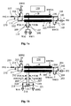
- the filter system preferably consists of a "pulp flow in” conduit PFI, inlet flow control system 510, filter part 500, filtrate and washing agent flow control system 520, outlet flow control system 530 and "pulp flow out” conduit PFO.
- the filter part 500 separates the said flow control systems from each other.
- the inlet flow control system 510 comprises a "rinsing water out” conduit RWO1 preferably connected to the flow channel. Also conduits “rinsing water out A" RWOA and “rinsing water out B" RWOB can be considered to belong in this system.
- the filtrate and washing agent flow control system 520 preferably comprises a "filtrate out” conduit FOA for the channel A a “filtrate out” conduit FOB for the channel B , the first "rinsing water in” conduit RWI1 and the “washing agent in” conduit WAI.
- the flow control system 530 on the outlet side preferably comprises a second "rinsing water in” conduit RWI2.
- the inlet flow control system 510 controls the pulp flow to either or both of the flow channels depending on the desired filtering mode and further depending on the valve settings chosen on the basis of the mode.
- the water suspension can be preferably directed to different channels independently of each other.
- rinsing liquids can be removed from the system through the inlet flow control system 510.
- the pressure from the process or a pump can be used as running power of the filtration.
- pump P4 is used, the pump being typically installed in inlet conduit PFI as shown in figures 1a-1c.
- the filtration pressure is typically adjusted so as to be between 0.1-5 bar, most preferably 0.5-2,5 bar.
- essentially solids-free filtrate for example 0.006-30 1/h while the magnitude of the pulp flowing through the apparatus is typically many times larger than the amount of filtrate.
- the filtrate and washing agent flow control system 520 directs the filtrate passing through the filters forward from the filtering apparatus, for example to recovery or an analysis apparatus.
- water and washing agent can be mixed in a suitable proportion to suit the current rinsing or washing stage.
- the pressure driving the liquids is arranged in the feed conduits WAI and RWI1 by means of pumps P1 and P2, correspondingly.
- the inlet flow control system, outlet flow control system and the filtrate and washing agent flow control system make it possible to use at least one filter for filtering and to simultaneously wash at least one other filter.
- These systems essentially make it possible to move between filtering and washing stages so that the filtrate flow is continuous. They can also make it possible to use at least two filters for filtering simultaneously.
- the outlet flow control system 530 directs the pulp flow out from the apparatus, adjusts the filtering pressure and directs rinsing water to various filtering channels through conduit RWI2, for example by means of pump P3, when needed.
- the conduits RWI1, RWI2, RWO1, RWOA RWOB, PFI, PFO, FOA, FOB and WAI and all other pipings and conduits of the apparatus between its components are preferably tubes or hoses.
- the liquid flows of the flow control systems are controlled by means of branches and valves arranged in the conduits.
- the filtering pressure can be adjusted by means of a pressure adjustment valve 115 preferably located in the outlet conduit PFO.
- the filtering pressure can be measured by means of meter or sensor 272 being typically in operational connection with the pressure adjustment filter 115, typically through control logic 150.
- the inlet valves 101 and 102 connected to the filtrate channels A and B, the outlet valves 112 and 114 as well as filtrate valves 19, correspondingly 17, are used for choosing which of the filters is used for producing the filtrate, i.e. whether the pulp is directed through channel A or B.
- the pulp can alternatively be simultaneously directed into both channels A and B (parallel operation), whereby all valves 101, 102, 112, 114, 109 and 107 are open.
- the filtrate is directed out through the filtrate valve 109 or 107 based on which of the filters is being used.
- the filtrate conduits FOA and FOB can be connected to each other after the filtrate valves so that the filtrate is directed from both channels to the same analysis apparatus or alternatively the filtrate tubes can direct the filtrate to one tank which is connected to the analysis apparatus. This makes it possible to continuously take samples with one analysis apparatus.
- the filtrate can be directed from both channels to different tanks or analysis apparatuses that can follow various parameters describing the status of the process. Having flowed through the flow channels the unfiltered pulp is usually directed back to the process via valves 112 and 114 depending on which filter is being used.
- the washing valves 110, 103, 111 and 105 or 108, 104, 113 and 106 connected to the channel used in the filtration are closed, correspondingly.
- Regenerating the filters, i.e. removing the solids trapped therein by washing can be carried out in various stages.
- the washing liquid can be fed into the filter and brought away from the filter either through flow channels or filtrate channels.
- the washing liquid is preferably either water or a solution of acid or base, such as sodium hydroxide solution, and this washing stage is called back flow wash, because the flow of the washing liquid is preferably essentially countercurrent with the flows of process solutions during the filtration.
- the washing liquid is preferably water and thus this phase is called rinsing.
- the washing can preferably be divided into four sequences: water rinsing, rinsing the pores, back flow washing with water and back flow washing with washing agent, such as
- water rinsing rinsing the pores
- back flow washing with water back flow washing with washing agent
- the washing liquids are preferably introduced into both filtering channels with the same washing pumps.
- there are three washing pumps i.e. two water pumps P2 and P3 and one washing agent pump P1.
- the intake of the water pumps P2 and P3 is preferably connected to the water line or water tank of the building.
- the intake of the washing agent pump P1 is preferably in the washing agent tank, such as an acid or base tank, for example in a sodium hydroxide tank.
- the flow of washing liquids in the filtering channels is controlled by means of shut-off valves, the valves being most probably remote controlled so that they can be attached to an automatic control system.
- the valves can be, for example, electrically, pneumatically or hydraulically operated.
- both filtering channels comprise their own washing liquid pumps (6 pieces totalll told) is not excluded, but by means of using just three pumps and a number of valves considerable economical savings are achieved.
- Separate washing agent pumps can also be used, if the filtering channels are provided with different filters that are being used for producing filtrate to two different analysis apparatuses, as has been described above, whereby it may be preferable to wash them with various washing agent solutions. Even in this case the feed of two different washing solutions can be carried out by means of a T connector located at the inlet conduit of the washing agent pump P 1 or other branch means and remote-controlled valves located in the formed branches.
- filters with different pore sizes are used in filtration channels, it is preferred to be able to change the filtration pressure accordingly. This can be achieved, for example, by means of separate throttle valves located in the channels or by means of one throttle adjustable according to the filtering stages. Otherwise there is the risk that one filter does not produce filtrate or it produces only a small amount of filtrate.
- valves 111 and 113 During the rinsing of the pores only the pump P3 is running and water is fed into the flow channels only through valves 111 and 113.
- the corresponding outlet valves 103 and 104 of the flow channels are, however, closed and the outlet valves 105 and 106 of the filtrate channels are open, whereby the rinsing water flows totally through the pores of the filter in the filtration direction and causes the desired rinsing effect.
- the valves 107, 108, 109 and 110 must then be closed for preventing flow of rinsing water into the filtrate tank, analysis apparatus or pumps P1 and P2.
- the back flow washing by means of water or acid solution is effected using the pressure created by pump P2 or P1 as the valves 103 and 110 being in connection with the channel A are open or correspondingly as the valves 104 and 108 being in connection with the channel B are open.
- water or acid solution flows from the filtrate channels through the pores against the direction of the filtering into the flow channels and discharges the pulp particles transferred into the pores through valve 103 or 104.
- the valves 101, 102, 109, 107, 212 and 214 are open.
- the pressure in the filters is halved, in case the adjustment of the throttle 115 is not changed.
- the production rate of the filtrate is not essentially changed, even though both filters filter simultaneously.
- the yield rate of the filtrate changes preferably less than 20%, typically less than 10%, even less than 5%, when the filtration is changed from one channel to another.
- the filtrate produced by means of the apparatus can also be kept very constant in quality over a number of filtering cycles.
- a constant quality filtrate means filtrate that one ideal, non-clogging crossflow filter would give with the same filtering parameters and pulp mass flow.
- the parallel use phase is so long that a just cleaned, and thus either empty or full of water, filtering channel fills with pulp and starts to produce constant quality filtrate.
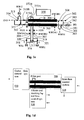
- Figure 1b illustrates a variation of the apparatus of figure 1a.
- the reference number 201 of figure 1b corresponds to the reference number 101 in figure 1a, reference number 202 to reference number 102 and so on.
- second, channel-specific rinsing water outlet conduits and valves RWOA2 and 219 and RWOB2 and 220 correspondingly, have been added to the filtrate and washing agent flow control system.
- the advantage of this embodiment is that in the washing stage the pores, filtration channels and filtration transfer conduits can be rinsed concurrently as well.
- the feed system of water and washing agent has been modified by adding two feed valves thereto, whereby the water and washing agent are mixed only after valves 216, 217, 218 and 221 separately for each channel.
- This solution makes it possible to introduce washing agents more flexibly separately for each channel.
- the second channel can, for example, be rinsed with clean water and the other can be simultaneously washed with washing agent.
- Figure 1c illustrates a system further differing from those shown in figures 1a and 1b, the system comprising modified inlet and outlet flow control systems:
- the filters are preferably arranged in filter cassettes of one, two or more filters, the cassettes being easily interchangeable and having connectors or conduits for connecting them between the different partial systems of the apparatus.
- ultrasound generators and/or ultrasound sensors can be installed near the filters, preferably on the side of the filter cassettes, for increasing the efficiency of the washes.
- Such apparatuses are manufactured in Finland by, for example, Finnsonic Oy.
- the pumps P1, P2 and P3 are preferably hose pumps, centrifugal pumps or mono pumps or other suitable pumps.
- the pumps P1 and P2 are hose pumps, P3 a centrifugal pump and pulp feed pump P4 a mono pump.
- the apparatus also comprises a control system comprising a control means 150, 250, 350 for causing a desired filtering cycle, e.g. such as shown in figures 2a and 2b and the co-operation of valves and pumps as shown in tables 1 and 2 as well as handle the sequence timings, i.e. switching them on and off.
- the control means 150, 250, 350 comprises, for example, a computer and an adjustment means. A number of different filtering and washing sequences as well as their timings for each filtering channel can be programmed into the control means.
- the adjustment means receives timing commands for valves and pumps from the computer and transfers the necessary control commands or drive voltages to pumps and valves via transfer means.
- the transfer means preferably comprise electric wires, but in the case of valves hoses or tubes of pressurized air or hydraulic hoses or tubes are also possible, depending on the type of the valve.
- the control system can also comprise means for monitoring the status of the filtering process. These means can comprise, for example, pressure and flow sensors, liquid level sensors, viscosity sensors and cameras.
- the control system can additionally receive data about the quality of the filtrate from the analysis apparatus and, when necessary, adjust e.g. filtering pressure or the durations of filtering and washing sequences.
- the control system can be made to operate fully automatically, semi-automatically or manually. It can also be a so-called suggesting system, whereby the operator must accept the control commands or at least some of them before they are executed. In such a situation the system can send the operator, for example, a visual or audible signal.
- the filtering and washing sequences can be set to operate automatically in a certain order and at certain times by the control system.
- the washing sequence preferably comprises a back flow wash with sodium hydroxide or some other acid or base solution suitable for ceramic filters as well as multiple rinsing with water, as has been disclosed in the above.
- the filtering and washing sequences alternate between the filters so that one of filters is constantly filtering. Just before one filter goes into washing stage the other starts filtering. This guarantees a continuous flow of filtrate in outlets FOA and FOB.
- both filters can be used singly or they can both be turned to filtering or washing stage simultaneously.
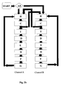
- a typical wash according to the disclosed method is carried out according to the program diagram shown in figures 2a or 2b.
- the letters C - I refer to different filtering and washing sequences, whereby
- the operator must decide whether to use channels A and B alternatingly, separately or simultaneously.
- the system will preferably execute the washing sequences of the current phase (typically over step G), and stops to wait for a start command from the operator. This avoids standing the filters in an unwashed state and thus a clogging caused by the stoppage.
- the total duration (steps D, E, F and G) of a washing stage guaranteeing a sufficient washing result is in duration a fraction of the duration of the filtering stage, but at the most the duration of the filtering stage, such as 1-10 minutes, typically 4-6 minutes.
- the various stages of the method can be timed in advance or they can be controlled by following the state of the process.
- the filtering stage can be ended, for example, when the flow resistance of the filtering material has exceeded a certain limit, e.g. at least 20 % of the beginning of the filtering stage, whereby the water suspension to be filtered is directed into the regenerated filter.
- valve-specific sequence diagram of figure 2a is shown in table 1 and the valve-specific sequence diagram of figure 2b is shown in table 2.
- table 1 an apparatus of figure 1a is used as the example and in the case of table 2 an apparatus according figure 1b is used.
- all shown apparatuses, but also apparatuses of other kind that haven't been described here in detail, can be used carrying out the shown sequences as well as many other preferred sequences within the basic principle disclosed in this document.
- the operation times and order of the sequences can vary considerably from the above within the basic idea of the invention in an example suitable for treating paper pulp, for example.
- the ceramic crossflow filters are manufactured essentially of aluminum oxide, a material that has been found to be suitable specially for the filtering of high-consistency pulp.
- the aluminum oxide filters contain considerable amounts, such as 1-20 %, of other compounds, such as silicon dioxide for ease of sintering.
- the advantages of aluminum oxide are its availability, price, chemical stability and modifiable pore size.
- Other possible filter materials are, among others, silicon carbide, silicon nitride and aluminum nitride as well as other ceramic filter materials.
- the length of one filter is 10-150 cm, preferably 25-80 cm, the diameter is 10-100 mm, preferably 25-42 mm, pore size 0.01-25 ⁇ m, preferably 0.05-5 ⁇ m and the number of flow channels is 1-100, preferably 1-19.
- the channels can be provided with different filters.
- the filters can also be of other material or they can be coated with a suitable plastic inert material for reducing accumulation of dirt.
- Ceramic filters cartridges are typically placed in a shell restricting the running of flows into the desired conduits. Preferably the cartridges are changeable.
- the filter apparatus consists of two (or more) independently operating filter units (the filter cartridges with their shells), the conduits leading thereto and therefrom being connected to each other by valves and hoses or tubes.
- the filter units operate in any position, because the pulp and rinsing water flowing through the filter prevent accumulation of gas in the filter.
- the filters are positioned parallel in a vertical position, whereby the apparatus can be made to have a small footprint. Additionally, the filter cassettes located in a vertical position can be easily changed via the side of the apparatus.
- the main flow direction of the pulp can be either downwards or upwards.
- the apparatus can be manufactured on a transport carriage or a transport trellis having, for example, wheels, whereby it can be easily transported. Table 1.
Landscapes
- Chemical & Material Sciences (AREA)
- Chemical Kinetics & Catalysis (AREA)
- Engineering & Computer Science (AREA)
- Water Supply & Treatment (AREA)
- Life Sciences & Earth Sciences (AREA)
- Hydrology & Water Resources (AREA)
- Environmental & Geological Engineering (AREA)
- Organic Chemistry (AREA)
- Ceramic Engineering (AREA)
- Inorganic Chemistry (AREA)
- Geology (AREA)
- Filtering Materials (AREA)
Applications Claiming Priority (1)
| Application Number | Priority Date | Filing Date | Title |
|---|---|---|---|
| FI20051121A FI20051121L (fi) | 2005-11-04 | 2005-11-04 | Menetelmä ja laite kiintoainepitoisten vesisuspensioiden suodattamiseksi |
Publications (1)
| Publication Number | Publication Date |
|---|---|
| EP1782874A1 true EP1782874A1 (fr) | 2007-05-09 |
Family
ID=35458730
Family Applications (1)
| Application Number | Title | Priority Date | Filing Date |
|---|---|---|---|
| EP06396019A Withdrawn EP1782874A1 (fr) | 2005-11-04 | 2006-11-03 | Procédé et dispositif pour la filtration des suspensions aqueuses contenant des solides |
Country Status (2)
| Country | Link |
|---|---|
| EP (1) | EP1782874A1 (fr) |
| FI (1) | FI20051121L (fr) |
Cited By (9)
| Publication number | Priority date | Publication date | Assignee | Title |
|---|---|---|---|---|
| EP2263783A1 (fr) * | 2009-05-25 | 2010-12-22 | Mitsubishi Heavy Industries, Ltd. | Système de déshydratation à membrane |
| US8142662B2 (en) | 2009-05-13 | 2012-03-27 | Mitsubishi Heavy Industries, Ltd. | Dehydrating system and method for control of spare membrane unit |
| CN101898089B (zh) * | 2009-05-27 | 2013-11-06 | 三菱重工业株式会社 | 脱水系统 |
| WO2016151151A1 (fr) * | 2015-03-24 | 2016-09-29 | Bas Tech International S.L. | Système de filtration compact auto-nettoyant à membrane céramique d'ultrafiltration |
| ES2592979A1 (es) * | 2016-08-08 | 2016-12-02 | Ivan CRESPO DE ANA | Método y sistema de filtración tangencial para licor mezcla de agua. |
| CN108479143A (zh) * | 2018-04-28 | 2018-09-04 | 南京科技职业学院 | 一种旁滤净水系统 |
| CN109855914A (zh) * | 2019-03-07 | 2019-06-07 | 苏州奥特福环境科技有限公司 | 一种用于河道水质监测系统的双通道采样装置及方法 |
| CN112703047A (zh) * | 2018-09-21 | 2021-04-23 | 思拓凡瑞典有限公司 | 灌注生物处理系统和其操作方法 |
| EP3932527A4 (fr) * | 2019-02-26 | 2022-12-14 | Toray Industries, Inc. | Procédé pour faire fonctionner une unité de filtration à membrane et unité de filtration à membrane |
Citations (3)
| Publication number | Priority date | Publication date | Assignee | Title |
|---|---|---|---|---|
| EP0512736A2 (fr) | 1991-05-06 | 1992-11-11 | Rohm And Haas Company | Procédé et appareil d'ultrafiltration pour récupération de latex polymériques à partir de lessive fraîche |
| US6485649B1 (en) | 1997-11-12 | 2002-11-26 | Steris Europe, Inc. | Method and device for the production of pure water |
| WO2004106697A1 (fr) | 2003-05-30 | 2004-12-09 | Vws Westgarth Limited | Appareil et procede pour traiter un fluide d'injection |
-
2005
- 2005-11-04 FI FI20051121A patent/FI20051121L/fi not_active IP Right Cessation
-
2006
- 2006-11-03 EP EP06396019A patent/EP1782874A1/fr not_active Withdrawn
Patent Citations (3)
| Publication number | Priority date | Publication date | Assignee | Title |
|---|---|---|---|---|
| EP0512736A2 (fr) | 1991-05-06 | 1992-11-11 | Rohm And Haas Company | Procédé et appareil d'ultrafiltration pour récupération de latex polymériques à partir de lessive fraîche |
| US6485649B1 (en) | 1997-11-12 | 2002-11-26 | Steris Europe, Inc. | Method and device for the production of pure water |
| WO2004106697A1 (fr) | 2003-05-30 | 2004-12-09 | Vws Westgarth Limited | Appareil et procede pour traiter un fluide d'injection |
Cited By (11)
| Publication number | Priority date | Publication date | Assignee | Title |
|---|---|---|---|---|
| US8142662B2 (en) | 2009-05-13 | 2012-03-27 | Mitsubishi Heavy Industries, Ltd. | Dehydrating system and method for control of spare membrane unit |
| EP2263783A1 (fr) * | 2009-05-25 | 2010-12-22 | Mitsubishi Heavy Industries, Ltd. | Système de déshydratation à membrane |
| CN101898089B (zh) * | 2009-05-27 | 2013-11-06 | 三菱重工业株式会社 | 脱水系统 |
| WO2016151151A1 (fr) * | 2015-03-24 | 2016-09-29 | Bas Tech International S.L. | Système de filtration compact auto-nettoyant à membrane céramique d'ultrafiltration |
| ES2592979A1 (es) * | 2016-08-08 | 2016-12-02 | Ivan CRESPO DE ANA | Método y sistema de filtración tangencial para licor mezcla de agua. |
| CN108479143A (zh) * | 2018-04-28 | 2018-09-04 | 南京科技职业学院 | 一种旁滤净水系统 |
| CN112703047A (zh) * | 2018-09-21 | 2021-04-23 | 思拓凡瑞典有限公司 | 灌注生物处理系统和其操作方法 |
| US12195715B2 (en) | 2018-09-21 | 2025-01-14 | Cytiva Sweden Ab | Perfusion bioprocessing system and method of operating the same |
| EP3932527A4 (fr) * | 2019-02-26 | 2022-12-14 | Toray Industries, Inc. | Procédé pour faire fonctionner une unité de filtration à membrane et unité de filtration à membrane |
| US12383867B2 (en) | 2019-02-26 | 2025-08-12 | Toray Industries, Inc. | Method for operating membrane filtration unit and membrane filtration unit |
| CN109855914A (zh) * | 2019-03-07 | 2019-06-07 | 苏州奥特福环境科技有限公司 | 一种用于河道水质监测系统的双通道采样装置及方法 |
Also Published As
| Publication number | Publication date |
|---|---|
| FI20051121A7 (fi) | 2007-05-05 |
| FI20051121L (fi) | 2007-05-05 |
| FI20051121A0 (fi) | 2005-11-04 |
Similar Documents
| Publication | Publication Date | Title |
|---|---|---|
| JP4198760B2 (ja) | 吸着膜による吸着式物質分離装置 | |
| CN109641178B (zh) | 使用中空纤维膜元件进行过滤和反冲洗的方法 | |
| US8128829B2 (en) | Cross flow filter device | |
| EP1782874A1 (fr) | Procédé et dispositif pour la filtration des suspensions aqueuses contenant des solides | |
| CN86104888A (zh) | 悬浮液中固体的浓缩 | |
| CN211946959U (zh) | 过滤设备 | |
| CN104562165B (zh) | 一种智能过滤控制系统 | |
| US20080257824A1 (en) | Method and Apparatus for Water Purification and Regeneration of Micro-filtration Tubules | |
| DE10164555A1 (de) | Cross-Flow-Mikrofiltrationsanlage und Verfahren zum Betreiben einer Cross-Flow-Mikrofiltrationsanlage | |
| EP1458465B1 (fr) | Filtre a membranes, et système et méthode l'utilisant | |
| CN114249382A (zh) | 一种管式陶瓷膜的过滤方法 | |
| US5505854A (en) | Two continuous filtration system for supplying filtrate to automatic analyzers | |
| EP3892363B1 (fr) | Dispositif de filtration à membrane et procédé de nettoyage de dispositif de filtration à membrane | |
| CN108031291A (zh) | 一种多功能膜过滤系统 | |
| CN121911237A (zh) | 用于利用一次性流动路径元件处理生物过程液体的单元 | |
| CN110745910B (zh) | 一种蜂窝陶瓷膜过滤方法及过滤装置 | |
| FI109093B (fi) | Ohjausjärjestelmä | |
| US7820046B2 (en) | Filter assembly for sampling | |
| JP5287459B2 (ja) | 限外濾過フィルタの洗浄方法及び限外濾過フィルタを用いた現像装置 | |
| EP2981800B1 (fr) | Dispositif et procédé d'échantillonnnage, de préparation et d'analyse d'un échantillon | |
| US20080099399A1 (en) | Filtration system | |
| CN110404415A (zh) | 外置式mbr平板陶瓷膜水处理一体化装置及水处理方法 | |
| CN223654778U (zh) | 一种黑茶茶褐素提取用杂质过滤装置 | |
| CN223026904U (zh) | 一种反冲洗过滤器及液压支架 | |
| CN220495791U (zh) | 一种双介质自动反冲洗过滤器 |
Legal Events
| Date | Code | Title | Description |
|---|---|---|---|
| PUAI | Public reference made under article 153(3) epc to a published international application that has entered the european phase |
Free format text: ORIGINAL CODE: 0009012 |
|
| AK | Designated contracting states |
Kind code of ref document: A1 Designated state(s): AT BE BG CH CY CZ DE DK EE ES FI FR GB GR HU IE IS IT LI LT LU LV MC NL PL PT RO SE SI SK TR |
|
| AX | Request for extension of the european patent |
Extension state: AL BA HR MK YU |
|
| 17P | Request for examination filed |
Effective date: 20071109 |
|
| AKX | Designation fees paid |
Designated state(s): AT BE BG CH CY CZ DE DK EE ES FI FR GB GR HU IE IS IT LI LT LU LV MC NL PL PT RO SE SI SK TR |
|
| 17Q | First examination report despatched |
Effective date: 20080709 |
|
| STAA | Information on the status of an ep patent application or granted ep patent |
Free format text: STATUS: THE APPLICATION IS DEEMED TO BE WITHDRAWN |
|
| 18D | Application deemed to be withdrawn |
Effective date: 20100420 |