EP1782906B1 - Méthode de contrôle d'une source de puissance pour soudage à l'arc avec électrode consommable - Google Patents
Méthode de contrôle d'une source de puissance pour soudage à l'arc avec électrode consommable Download PDFInfo
- Publication number
- EP1782906B1 EP1782906B1 EP06255619.6A EP06255619A EP1782906B1 EP 1782906 B1 EP1782906 B1 EP 1782906B1 EP 06255619 A EP06255619 A EP 06255619A EP 1782906 B1 EP1782906 B1 EP 1782906B1
- Authority
- EP
- European Patent Office
- Prior art keywords
- voltage
- welding
- value
- current
- norm
- Prior art date
- Legal status (The legal status is an assumption and is not a legal conclusion. Google has not performed a legal analysis and makes no representation as to the accuracy of the status listed.)
- Ceased
Links
Images









Classifications
-
- B—PERFORMING OPERATIONS; TRANSPORTING
- B23—MACHINE TOOLS; METAL-WORKING NOT OTHERWISE PROVIDED FOR
- B23K—SOLDERING OR UNSOLDERING; WELDING; CLADDING OR PLATING BY SOLDERING OR WELDING; CUTTING BY APPLYING HEAT LOCALLY, e.g. FLAME CUTTING; WORKING BY LASER BEAM
- B23K9/00—Arc welding or cutting
- B23K9/06—Arrangements or circuits for starting the arc, e.g. by generating ignition voltage, or for stabilising the arc
- B23K9/073—Stabilising the arc
- B23K9/0731—Stabilising of the arc tension
Definitions
- the present invention relates to a method for controlling the output from a consumable electrode arc welding power source.
- the present invention relates to a method for removing abnormal voltages superposed on the welding voltage, so that the control of the welding power source is performed based on the normalized welding voltage, thereby stabilizing the state of the welding.
- the consumable electrode arc welding power source performs constant-voltage control.
- the arc length is detected from the welding voltage based on the proportional relation between the arc length and the welding voltage, and the arc length is maintained at an appropriate value by providing an output control so that the welding voltage becomes equal to a preset voltage value that will give the appropriate arc length.
- highly accurate detection of the arc length must be made from the welding voltage.
- the apparent arc length changes by a very little amount in a short moment which is not greater than several tens of milliseconds because changes of the apparent arc length are caused by the difference between the wire feeding speed and the wire melting speed.
- the migration of the cathode point which can be caused by many factors as described above introduces an abnormal voltage superimposed on the welding voltage.
- This abnormal voltage does not have any proportional relation with the apparent arc length. Therefore, if the output control is based on the welding voltage on which the abnormal voltage is superimposed, the abnormal voltage destabilizes the arc length control system, leading to decreased welding quality.
- Abnormal voltage appears more often in MIG welding and MAG welding in which shield gas is mixed with inert gas (such as argon gas and helium gas).
- JP 2004-237342 describes a method relating to consumable electrode pulse arc welding, and involving amplifying the difference between the welding voltage detection unit and the welding voltage setting unit.
- Fig. 15 is a chart showing voltage and current waveforms in a consumable electrode pulse arc welding. A time course change of the welding voltage v is shown in (A) whereas a time course change of the welding current i is shown in (B). Explanation will be given below with reference to Fig 13 .
- a transient current which rises from a base current to a peak current flows as shown in (B), and a transient voltage which rises from a base voltage to a peak voltage is applied between the welding wire and the base metal as shown in (A).
- a predetermined peak period Tp from time instant t2 to time instant t3 a predetermined peak current flows as shown in (B), and a peak voltage is applied as shown in (A).
- a transient current which falls from the peak current to the base current flows as shown in (B), and a transient voltage which falls from the peak current to the base current is applied as shown (A).
- a base period Tb from time instant t4 to time instant t5 a predetermined base current passes flows as shown in (B), whereas a base voltage is applied as shown in (A).
- an abnormal voltage which has a greater value than the normal voltage is superimposed on the base voltage during the base period Tb.
- control is made by varying the length of the base period Tb so that an average value of the welding voltage v would be equal to a preset voltage value. Therefore, if an abnormal voltage is superimposed on the welding voltage v, error is contained in the arc length detection which is performed on the basis of the welding voltage average value, and the error destabilizes the arc length control.
- Fig. 16 illustrates a method of setting a norm voltage waveform for removing the abnormal voltage.
- a norm peak voltage value Vpc, a norm base voltage value Vbc and a fluctuation range ⁇ Vc for a given set of welding conditions such as the kind of welding wire and wire feeding speed are obtained through e.g. experiments.
- the norm voltage waveform is defined by using the following formulas for each lapse of time t, with the start time point of the peak rise period Tup set to be 0 [s].
- Fig. 17 is a waveform chart which shows how an abnormal voltage is removed by using the above-described norm voltage waveform.
- the waveform of the welding voltage v on which an abnormal voltage is superimposed is shown in (A) as described in Fig. 15
- the waveform of the welding voltage limit value vf is shown in (B).
- Fig. 18 is a chart showing voltage and current waveforms in consumable electrode arc welding.
- a time course change of a welding voltage v is shown in (A)
- a time course change of a welding current I is shown in (B).
- the welding voltage v becomes a short-circuit voltage value of a few volts as shown in (A)
- the welding current i increases gradually as shown in (B).
- the arc is not generated and the cathode point is not formed, and thereby no abnormal voltage is generated.
- the welding voltage v becomes an arc voltage value, and the welding current i decreases gradually as shown in (B).
- An abnormal voltage occurs during the arc period Ta, as illustrated between time points t4-t5. Since the welding power source is under constant-voltage control, occurrence of an abnormal voltage, i.e. a voltage surge, will cause the welding current i to drop sharply as shown in (B). This change of the current can be a trigger for an unstable arc state.
- the abnormal voltage is caused by the same factors as described for the case of pulse arc welding.
- the abnormal voltage removal method according to the conventional technique for pulse arc welding is not applicable to the abnormal voltage in the above-described consumable electrode arc welding.
- pulse arc welding it is possible to set normal values of the welding voltage for the peak period and for the base period in the form of the norm peak voltage value Vpc and the norm base voltage value Vbc. Therefore, it is possible to define a norm voltage waveform by using these values.
- time course change of the welding voltage v during the arc period Ta varies very diversely depending on the arc load. Because of this, it is not possible, unlike in pulse arc welding described with reference to Fig. 14 , to set a norm voltage waveform for each time period. Therefore, it has not been possible to remove abnormal voltages included in the welding voltage with the conventional means in consumable electrode arc welding.
- the present invention provides an output control method for a consumable electrode non-pulse arc welding power source in which an output of the welding power source is controlled based on an amplified error value between a predetermined voltage setting value and a welding voltage characterized in that an entire application range of a welding current is segmentalized into a plurality of current zones, a norm welding voltage value is set for each of the current zones, a welding current and a welding voltage are detected at each of minute cycles, one of the current zones which corresponds to a value of the detected welding current is selected, a fluctuation range is calculated with the norm welding voltage value of the selected current zone as a center value, a welding voltage limit value is calculated while the detected value of the welding voltage is limited to within the fluctuation range, and the amplified error value is calculated using the voltage setting value and the welding voltage limit value.
- a moving average of the welding voltage limit values is obtained for each of the current zones for the calculation of the norm welding voltage value for each of the current zones.
- an output voltage which is a voltage at a point on an output path in the welding power source before the reactor mounted on the output path is detected, a deviation between the detected value of the welding voltage and the welding voltage limit value is calculated, a voltage control setting value is calculated by adding the deviation to the voltage setting value, and the amplified error value is calculated using the voltage control setting value and the detected value of the output voltage.
- each of the norm welding voltage values in all of the current zones is modified based on a change amount of the voltage setting value in the case that the voltage setting value changes.
- abnormal voltages superimposed on the welding voltage in consumable electrode arc welding is removed by setting a plurality of current zones and setting a norm welding voltage value and defining a fluctuation range for each of the current zones.
- the voltage control setting value is calculated by modifying the voltage setting value with the deviation between the welding voltage and the welding voltage limit value, and the output of the welding power source is controlled with the amplified error value between the output voltage which is a voltage value at the point in the welding power source before the reactor and the voltage control setting value.
- the norm welding voltage or the norm characteristic is modified in accordance with the change of the voltage setting value. Accordingly, the abnormal voltage is removed with high response in the case that the voltage setting value changes.
- a norm characteristic suitable for the welding condition of various portions to be welded is set by providing various norm characteristics for a plurality of portions to be welded. Accordingly, stable output control is performed in welding each of the portions to be welded based on the welding voltage from which an abnormal voltage is properly removed.
- Fig. 1 shows a current-voltage relation and describes a principle of a method for removing abnormal voltages according to the present invention.
- the horizontal axis in the figure represents a welding current I whereas the vertical axis represents a welding voltage v.
- This figure includes circles indicating operational points of voltage and current waveform shown in Fig. 16 sampled at each minute time (from several tens of microseconds to several hundreds of microseconds).
- explanation will be given with reference to this figure.
- the curve L1 shows a trajectory of operational points during the short-circuit period Ts.
- the operational point moves on the curve from left to right as time passes.
- the curve L2 shows a trajectory of operational points during the arc period Ta.
- the operation point moves from right to left as time passes.
- the short-circuit period Ts begins again and the above-described operation is repeated.
- the operation point moves along the curve L3 during the period the abnormal voltage generates. Since the normal arc period Ta with no abnormal voltage generated is represented by the curve L2, clear distinction is possible from those operational points in the time period in which an abnormal voltage is generated.
- norm operational point trajectory the trajectory of tie operational points during the normal arc period Ta as x1-x2 (hereinafter referred to as norm operational point trajectory), and by treating operational points deviating from the norm operational point trajectory by a predetermined fluctuation range as occurrence of the abnormal voltage for limitation procedure.
- the norm operational point trajectory is calculated based on e.g. experiment for each set of welding conditions.
- Fig. 2 is a chart showing current-voltage relation and describes a method for calculating the norm welding voltage value Vc from the above-described norm operational point trajectory curve x1-x2.
- the horizontal axis represents the welding current i whereas the vertical axis represents the welding voltage v.
- the norm operational point trajectory shown in the figure is the same as one described with reference to Fig.1 .
- the entire range of the welding current i is divided into a plurality of current zones CZ(n). For example, if current zones of 25A width are considered with regard to a welding power source of a 500A current capacity, twenty current zones CZ(1)-CZ(20) are produced.
- a norm welding voltage value Vc(n) is set for each current zone CZ(n) on the norm operational point trajectory x1-x2.
- a current zone CZ(n) is selected in accordance with a detected welding current value i(n) for each time segment, which will then gives a norm welding voltage value Vc(n) for this particular current zone CZ(n).
- Fig. 3 is a chart showing current and voltage waveforms and illustrates a method of removing abnormal voltages according to Embodiment 1 of the present invention.
- a waveform of the welding current i during the arc period Ta is shown in (A) whereas a waveform of the welding voltage v and a waveform of the welding voltage limit value vf are shown in (B) by a broken line and a solid line, respectively.
- (A) shows a case in which the current zone is divided into four segments CZ(1)-CZ(4).
- a norm welding voltage value is set to Vc(1)-Vc(4) by using the method described with reference to Figs. 1 and 2 .
- Each current zone has a fluctuation range of the same width, i.e. ⁇ Vc; however, each current zone may have a different fluctuation range from others.
- the broken line represents the norm welding voltage value while the dashed-dotted lines represent the upper limit value and the lower limit value of the fluctuation range. Measurement is performed for the welding current i and the welding voltage v, in each time segment.
- the current zone CZ(3) is selected based on the value of the welding current i(n).
- the norm welding voltage value Vc(3) is identified and the fluctuation range Vc(3) ⁇ Vc is also identified.
- the welding voltage limit value vf(n) v(n).
- the current zone CZ(2) is selected based on the value of welding current i(m).
- the norm welding voltage value Vc(2) and then the fluctuation range Vc(2) ⁇ Vc are determined.
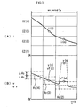
- Fig. 4 is a waveform chart showing a case where the above-described method of removing abnormal voltages is applied to the voltage-current waveform in Fig. 18 .
- an abnormal voltage is interposed during the period between time points t4-t5.
- the abnormal voltage is removed by using the above-described method, and the welding voltage limit value vf is formed. Since the welding power source controls its output based on the welding voltage limit value vf, the welding current i changes in the substantially manner as in the normal case as shown in (B). As a result, the arc length is controlled stably, enabling to obtain good welding quality.
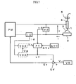
- Fig. 5 is a block diagram of a consumable electrode arc welding power source according to Embodiment 1. Hereinafter, description will be made for each block with reference to the figure.
- a power source main circuit PM receives power such as three-phase 200 V from a commercial power supply, and performs output control such as inverter control and thyristor phase control based on a voltage error amplification signal Ev described later to output a welding current i and a welding voltage v.
- a welding wire 1 is supplied through a welding torch 4 by rotation of feeding rolls 5 of a wire feeder, whereby an arc 3 generates between the wire and a base metal 2 to perform welding.
- a current detection circuit ID samples the welding current i for each minute time and outputs a current detection signal id.
- a norm welding voltage value setting circuit VC which stores a norm welding voltage value for each of the segmentalized current zones as described with reference to Figs. 1 and 2 , selects a norm welding voltage value that corresponds to the current detection signal id, and outputs a norm welding voltage value signal Vc.
- a voltage detection circuit VD samples the welding voltage v at the same time of sampling of the welding current i, and outputs a voltage detection signal vd.
- a fluctuation range setting circuit ⁇ VC outputs a predetermined fluctuation range setting signal ⁇ Vc.
- a filter circuit FT limits, as described with reference to Fig. 3 , the value of the voltage detection signal vd to within the fluctuation range Vc ⁇ Vc which is a range defined with respect to the norm welding voltage value, and outputs a welding voltage limit value signal vf.
- a voltage setting circuit VR outputs a desired voltage setting signal Vr.
- a voltage error amplifying circuit EV amplifies an error between the voltage setting signal Vr and the welding voltage limit value signal vf to output a voltage error amplification signal Ev.
- Fig. 6 illustrates a method of calculating a norm welding voltage value for each current zone by using a moving average while welding is underway according to Embodiment 2 of the present invention.
- the figure shows a case where the current zone is divided into four segments CZ(1)-CZ(4).
- a welding current i(n) and a welding voltage v(n) are detected, a current zone CZ (p) which corresponds to the welding current i (n) is selected, and the welding voltage limit value is set to a value vf(n).
- This relationship will be expressed as vf (p, n).
- the expression vf(p, n) represents that the n-th welding voltage limit value Vf(n) belongs to the current zone CZ(p).
- the above example is a case where a total of eight data in the past are used to obtain the moving average.
- the moving average is obtained from welding voltage limit values only in the same current zone.
- the calculated norm welding voltage value Vc(4) is used to limit the next v(21), and then to obtain vf(4, 21).
- Vc(3) vf 3 , 23 + ... + vf 3 4 / 8
- Vc(2) vf 2 , 26 + ... + vf 2 6 / 8
- the norm welding voltage value Vc in each current zone is calculated automatically.
- the moving average is obtained for the period from past a few tens of milliseconds to past a few hundreds of milliseconds.
- Fig. 7 is a block diagram of a consumable electrode arc welding power source according to Embodiment 2.
- blocks which are identical to those in Fig. 5 are designated by the same references, and will not be given description.
- description will be made for the blocks drawn in broken lines which are different from those in Fig. 5 .
- a norm welding voltage value calculation circuit VCA receives the current detection signal id and the welding voltage limit value signal vf as inputs, classifies the welding voltage limit value signal vf in accordance with the value of the corresponding current detection signal id which is detected simultaneously therewith as described with reference to Fig. 6 , calculates a moving average for each current zone, and outputs a norm welding voltage value calculation signal Vca for each current zone.
- a second norm welding voltage value setting circuit VC2 stores the norm welding voltage value calculation signal Vca for each current zone as input, selects a norm welding voltage value of the current zone which corresponds to the current detection signal id, and outputs a norm welding voltage value signal Vc.
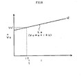
- Fig. 8 is a chart showing current-voltage relation and illustrates a method of Embodiment 3, not forming part of the present invention, for calculating a norm welding voltage value Vc from the norm operational point trajectory x1-x2 described earlier with reference to Fig. 1 .
- the horizontal axis represents the welding current i whereas the vertical axis represents the welding voltage v and the norm welding voltage value Vc.
- the norm operational point trajectory x1-x2 in the figure is the same as one described with reference to in Fig.1 .
- the norm operational point trajectory x1-x2 is an arc characteristic curve which shows a relation between the welding current i and the welding voltage v during the time when an arc is generated.
- This norm operational point trajectory x1-x2 is approximated as an approximating curve La, which is used as a setting that represents a norm characteristic.
- the approximating curve La may be a second-order or higher-order approximation of the norm operational point trajectory x1-x2.
- Fig. 9 is a chart showing current and voltage waveforms and illustrates a method of removing abnormal voltages according to Embodiment 3, not forming part of the present invention.
- a waveform of the welding current i in the arc period Ta is shown in (A) whereas waveforms of the welding voltage v and the welding voltage limit value vf are shown in (B) with broken and solid lines, respectively.
- Fig. 10 is a block diagram of a consumable electrode arc welding power source according to Embodiment 3.
- the same blocks as already described with reference to Fig. 5 are indicated with the same reference signs, and the description will not be repeated.
- description will be give to the blocks drawn in broken lines, which are different from those in Fig. 5 .
- a third norm welding voltage value setting circuit VC3 stores the approximating curve La of the norm operational point trajectory described with reference to Fig. 8 , receives the current detection signal id as an input, calculates a norm welding voltage value on the approximating curve La, and outputs a norm welding voltage value signal Vc.
- Embodiment 3 it is possible to remove abnormal voltages by setting the approximating curve La of the norm operational point trajectory, calculating the fluctuation range Vc ⁇ Vc of the norm welding voltage value, and then by limiting the welding voltage detected value vd to within this fluctuation range.
- Fig. 11 shows a current-voltage relation and describes a method according to Embodiment 4, not forming part of the present invention, for sequentially calculating and updating the approximating curve La of the norm operational point trajectory x1-x2 described with reference to Fig. 8 while welding is underway.
- the horizontal axis represents the welding current i whereas the vertical axis represents the welding voltage limit value vf and the norm welding voltage value Vc.
- the figure includes circles indicating operational points of the welding current i and the welding voltage limit value vf in the arc period in each predetermined calculation interval. The operational points are calculated as a combination of the welding current i and the welding voltage limit value vf for each minute cycles.
- the calculation cycle is set to a range from a few tens of milliseconds to a few seconds for example.
- Fig. 12 is a block diagram of a consumable electrode arc welding power source according to Embodiment 4, not forming part of the present invention.
- blocks which are identical with those in Fig. 5 are indicated with the same reference signs, and will not be described here.
- description will be made for the blocks drawn in broken lines which are different from those in Fig. 5 .
- An approximating curve calculation circuit LA receives the current detection signal id and the welding voltage limit value signal vf as input, calculates an approximating curve for each predetermined calculation cycle from operation points in the arc period within the calculation cycle, and outputs an approximating curve setting signal La.
- the approximating curve setting signal La is formed with constants a and b if the approximating curve is by first-order approximation.
- a fourth norm welding voltage value setting circuit VC4 receives the approximating curve setting signal La as an input, calculates a norm welding voltage value which corresponds to the value of the current detection signal id on the approximation curve, and outputs a norm welding voltage value signal Vc.
- Embodiment 4 it is possible to calculate and update the approximation curve La described in Embodiment 3 continually while the welding is underway. This enables to reduce the time for setting because it eliminates the need for conducting e.g. experiments in order to find an approximation curve which otherwise is necessary for each different set of welding conditions. Further, this enables to optimize the approximation curve in accordance with changing states of the welding, and therefore to remove the abnormal voltage accurately, making possible to perform good welding.
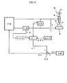
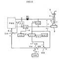
- Fig.13 is a block diagram of a consumable electrode arc welding power source according to Embodiment 5 of the present invention.
- the welding power sources according to Embodiments 1 through 4 described above perform feedback of the welding voltage v which is a voltage value passed through a reactor that is not illustrated and included in the power source main circuit PM for output control.
- the welding voltage v is a voltage between output terminals of the welding power source as well as a voltage between the welding wire and the base material.
- Embodiments 1 through 4 employ feedback of the welding voltage limit value vf obtained by removing an abnormal voltage from the welding voltage v in order to keep welding stable.
- Embodiment 5 employs a welding power source performing feedback control of the output voltage e which is a voltage at the portion before a reactor.
- e which is a voltage at the portion before a reactor.
- a second power source main circuit PM2 excludes a reactor WL which is the same as one included in the power source main circuit PM shown in Fig.5 , and operates similarly or outputs an output voltage e by control of output such as inverter control based on a amplified voltage error signal Ev.
- the reactor WL outputs a smoothed output voltage e to apply it between a welding wire 1 and a base material 2.
- the inductance value of the reactor WL for smoothing may be small when the inverter control frequency of the second power source main circuit PM2. Accordingly, if the wiring of th output path in the welding power source shows inductance enough for smoothing, the wiring acts as the reactor WL equivalently.
- the description "reactor" in claims means not only a reactor including an iron core around which a cable winds but also a reactor constituted of the wiring of the output path.
- An output voltage detecting circuit ED detects the above output voltage e and outputs an output voltage detection signal ed.
- An output voltage error amplifying circuit EA amplifies an error between the above voltage control setting signal Vcr and the above output voltage detection signal ed, and a voltage error amplifying signal Ev.
- the method to remove an abnormal voltage superimposed on the welding voltage v to generate the welding voltage limit value signal vf is same as one in Fig. 5 .
- Fig. 14 is a timing chart showing operation of the welding power source described above.
- the welding voltage v is shown in (A)
- the welding current i is shown in (B)
- the voltage control setting signal Vcr is shown in (C). This figure corresponds to Fig. 4 described above.
- description will be given with regard to the figure.
- the welding voltage v is equal to the welding voltage limit value vf because an abnormal voltage does not generate. Accordingly, as shown in (C), the voltage control setting signal Vcr is equal to the voltage setting signal Vr. During this period, thereby, the output voltage e is constant-voltage-controlled by the value of the voltage setting signal Vr.
- Embodiment 1 ( Fig. 5 ) is employed as generation of the welding voltage limit value signal vf.
- the methods of Embodiment 2 through 4 may be used.
- the voltage control setting value is calculated by modifying the voltage setting value with the deviation between the welding voltage and the welding voltage limit value. Accordingly, even if an abnormal voltage is superimposed, the output voltage is controlled based on it, whereby sharp change of the welding current is prevented to keep welding stable.
- the norm welding voltage values in each of the current zones are as follows: Vc 0 , Vc 2 , ... , Vc n ... , Vc 20
- the norm welding voltage value Vc is set to the neighborhood of the proper value by modifying the norm welding voltage value Vc in response to change of the voltage setting value Vr, whereby an abnormal voltage is properly removed.
- Vc a ⁇ i + b + K ⁇ Vr
- coefficient K is a constant approximately from 0.1 to 3.0.
- the norm characteristic is set to the neighborhood of the proper value by modifying the norm characteristic in response to change of the voltage setting value Vr, whereby an abnormal voltage is properly removed.
- the norm characteristic for each of the portions to be welded is updated.
- Embodiments 1 through 8 takes a case of short-circuited arc welding.
- the present invention is also applicable to globular transfer arc welding, spray transfer arc welding, consumable electrode AC arc welding, and so on. Further, the present invention is applicable to consumable electrode pulse arc welding.
Landscapes
- Engineering & Computer Science (AREA)
- Physics & Mathematics (AREA)
- Plasma & Fusion (AREA)
- Mechanical Engineering (AREA)
- Arc Welding Control (AREA)
Claims (4)
- Procédé de contrôle d'une source de puissance pour soudage à l'arc sans impulsion avec électrode consommable (PM) dans laquelle une sortie de la source de puissance de soudage (PM) est commandée sur la base d'une valeur d'erreur amplifiée entre une valeur de configuration de tension prédéterminée (Vc) et une tension de soudage (vd),
caractérisé en ce que l'ensemble de la plage d'application d'un courant de soudage est segmentée en une pluralité de zones de courant (CZ(n)), une valeur de tension de soudage standard (Vc(n)) est configurée pour chacune des zones de courant, un courant de soudage (id) et une tension de soudage (vd) sont détectées à chaque cycles de minutes, une des zones de courant (CZ(n)) qui correspond à une valeur du courant de soudage détecté est sélectionnée, une plage de fluctuation (ΔVC) est calculée avec la valeur de tension de soudage standard (Vc(n)) de la zone de courant sélectionnée servant de valeur centrale, une valeur de limite de tension de soudage (vf) est calculée alors que la valeur détectée de la tension de soudage est limitée dans la plage de fluctuation (ΔVC) et la valeur d'erreur amplifiée est calculée en utilisant la valeur de configuration de tension (Vc) et la valeur de limite de tension de soudage (vf). - Procédé selon la revendication 1, dans lequel une moyenne variable des valeurs de limite de tension de soudage est obtenue pour chacune des zones de courant (CZ(n)) pour le calcul de la valeur de tension de soudage standard (Vc(n)) pour chacune des zones de courant (CZ(n)).
- Procédé selon la revendication 1 ou 2, dans lequel une tension de sortie (ed) qui est une tension à un point sur une trajectoire de sortie de la source de puissance de soudage (PM) avant qu'un réacteur (WL) monté sur la trajectoire de sortie soit détectée, un écart entre la valeur détectée de la tension de soudage et la valeur de limite de tension de soudage (vf) est calculé, une valeur de configuration de commande de tension est calculée en ajoutant l'écart à la valeur de configuration de tension et la valeur d'erreur amplifiée est calculée en utilisant la valeur de configuration de commande de tension et la valeur détectée de la tension de sortie.
- Procédé selon la revendication 1 ou 2, dans lequel chacune des valeurs de tension de soudage standard (Vc(n)) dans toutes les zones de courant (CZ(n)) est modifiée sur la base d'une quantité de modification de la valeur de configuration de la tension (Vc) au cas où la valeur de configuration de la tension change.
Applications Claiming Priority (4)
| Application Number | Priority Date | Filing Date | Title |
|---|---|---|---|
| JP2005321816 | 2005-11-07 | ||
| JP2005354224 | 2005-12-08 | ||
| JP2006075818 | 2006-03-20 | ||
| JP2006176309A JP5214859B2 (ja) | 2005-11-07 | 2006-06-27 | 消耗電極アーク溶接電源の出力制御方法 |
Publications (2)
| Publication Number | Publication Date |
|---|---|
| EP1782906A1 EP1782906A1 (fr) | 2007-05-09 |
| EP1782906B1 true EP1782906B1 (fr) | 2016-10-05 |
Family
ID=37714520
Family Applications (1)
| Application Number | Title | Priority Date | Filing Date |
|---|---|---|---|
| EP06255619.6A Ceased EP1782906B1 (fr) | 2005-11-07 | 2006-11-01 | Méthode de contrôle d'une source de puissance pour soudage à l'arc avec électrode consommable |
Country Status (4)
| Country | Link |
|---|---|
| US (1) | US9278402B2 (fr) |
| EP (1) | EP1782906B1 (fr) |
| JP (1) | JP5214859B2 (fr) |
| CN (1) | CN1962148B (fr) |
Families Citing this family (42)
| Publication number | Priority date | Publication date | Assignee | Title |
|---|---|---|---|---|
| JP2010172958A (ja) * | 2009-02-02 | 2010-08-12 | Daihen Corp | プラズマgma溶接方法 |
| US10040143B2 (en) | 2012-12-12 | 2018-08-07 | Illinois Tool Works Inc. | Dabbing pulsed welding system and method |
| US10906114B2 (en) | 2012-12-21 | 2021-02-02 | Illinois Tool Works Inc. | System for arc welding with enhanced metal deposition |
| US9950383B2 (en) | 2013-02-05 | 2018-04-24 | Illinois Tool Works Inc. | Welding wire preheating system and method |
| US10835983B2 (en) * | 2013-03-14 | 2020-11-17 | Illinois Tool Works Inc. | Electrode negative pulse welding system and method |
| US9808879B2 (en) * | 2013-04-12 | 2017-11-07 | Isawe, Llc | Welding diagnostic device for identifying metal transfer modes during a welding process and a method of identifying metal transfer modes of a welding process |
| US11045891B2 (en) | 2013-06-13 | 2021-06-29 | Illinois Tool Works Inc. | Systems and methods for anomalous cathode event control |
| US10543549B2 (en) | 2013-07-16 | 2020-01-28 | Illinois Tool Works Inc. | Additive manufacturing system for joining and surface overlay |
| US10828728B2 (en) | 2013-09-26 | 2020-11-10 | Illinois Tool Works Inc. | Hotwire deposition material processing system and method |
| US10052707B2 (en) * | 2014-04-04 | 2018-08-21 | Lincoln Global, Inc. | Method and system to use AC welding waveform and enhanced consumable to improve welding of galvanized workpiece |
| US11154946B2 (en) | 2014-06-30 | 2021-10-26 | Illinois Tool Works Inc. | Systems and methods for the control of welding parameters |
| US11198189B2 (en) * | 2014-09-17 | 2021-12-14 | Illinois Tool Works Inc. | Electrode negative pulse welding system and method |
| US11478870B2 (en) | 2014-11-26 | 2022-10-25 | Illinois Tool Works Inc. | Dabbing pulsed welding system and method |
| US10189106B2 (en) | 2014-12-11 | 2019-01-29 | Illinois Tool Works Inc. | Reduced energy welding system and method |
| US11370050B2 (en) | 2015-03-31 | 2022-06-28 | Illinois Tool Works Inc. | Controlled short circuit welding system and method |
| US10974337B2 (en) | 2015-08-17 | 2021-04-13 | Illinois Tool Works Inc. | Additive manufacturing systems and methods |
| US11285559B2 (en) | 2015-11-30 | 2022-03-29 | Illinois Tool Works Inc. | Welding system and method for shielded welding wires |
| US10610946B2 (en) | 2015-12-07 | 2020-04-07 | Illinois Tool Works, Inc. | Systems and methods for automated root pass welding |
| US10675699B2 (en) | 2015-12-10 | 2020-06-09 | Illinois Tool Works Inc. | Systems, methods, and apparatus to preheat welding wire |
| US12194579B2 (en) | 2015-12-10 | 2025-01-14 | Illinois Tool Works Inc. | Systems, methods, and apparatus to preheat welding wire |
| CN108883485B (zh) * | 2016-03-29 | 2020-07-14 | 松下知识产权经营株式会社 | 电弧焊接控制方法 |
| JP6835449B2 (ja) * | 2016-07-15 | 2021-02-24 | 株式会社ダイヘン | アーク溶接電源の出力制御方法 |
| US10766092B2 (en) | 2017-04-18 | 2020-09-08 | Illinois Tool Works Inc. | Systems, methods, and apparatus to provide preheat voltage feedback loss protection |
| US10870164B2 (en) | 2017-05-16 | 2020-12-22 | Illinois Tool Works Inc. | Systems, methods, and apparatus to preheat welding wire |
| US11590598B2 (en) | 2017-06-09 | 2023-02-28 | Illinois Tool Works Inc. | Systems, methods, and apparatus to preheat welding wire |
| CN111386168A (zh) | 2017-06-09 | 2020-07-07 | 伊利诺斯工具制品有限公司 | 具有两个接触焊嘴和用于冷却并传导电流的制冷主体的用于焊接炬的焊接组装件 |
| CN111315524A (zh) | 2017-06-09 | 2020-06-19 | 伊利诺斯工具制品有限公司 | 具有两个触头和用于将电流传导至触头的多个液冷组件的焊接炬 |
| EP3634684B1 (fr) | 2017-06-09 | 2022-10-05 | Illinois Tool Works Inc. | Chalumeau de soudage doté d'une première pointe de contact pour préchauffer un fil de soudage et d'une seconde pointe de contact |
| US11524354B2 (en) | 2017-06-09 | 2022-12-13 | Illinois Tool Works Inc. | Systems, methods, and apparatus to control weld current in a preheating system |
| US11020813B2 (en) | 2017-09-13 | 2021-06-01 | Illinois Tool Works Inc. | Systems, methods, and apparatus to reduce cast in a welding wire |
| US10792682B2 (en) | 2017-10-02 | 2020-10-06 | Illinois Tool Works Inc. | Metal manufacturing systems and methods using mechanical oscillation |
| CN108031952B (zh) * | 2017-12-21 | 2019-08-20 | 唐山松下产业机器有限公司 | 熔化极气体保护焊的控制方法、装置、介质及电子设备 |
| CN113165097B (zh) | 2018-08-31 | 2023-11-03 | 伊利诺斯工具制品有限公司 | 用于电阻式地预加热电极丝的埋弧焊系统和埋弧焊焊炬 |
| US11014185B2 (en) | 2018-09-27 | 2021-05-25 | Illinois Tool Works Inc. | Systems, methods, and apparatus for control of wire preheating in welding-type systems |
| JP7170373B2 (ja) * | 2018-12-14 | 2022-11-14 | 株式会社ダイヘン | 複合溶接方法 |
| EP3898055A2 (fr) | 2018-12-19 | 2021-10-27 | Illinois Tool Works, Inc. | Systèmes, procédés et appareil pour préchauffer un fil de soudage |
| US12583048B2 (en) | 2019-03-29 | 2026-03-24 | Illinois Tool Works Inc. | Methods and apparatus to convert welding-type power to welding-type power and resistive preheating power |
| US12103121B2 (en) | 2019-04-30 | 2024-10-01 | Illinois Tool Works Inc. | Methods and apparatus to control welding power and preheating power |
| US11772182B2 (en) | 2019-12-20 | 2023-10-03 | Illinois Tool Works Inc. | Systems and methods for gas control during welding wire pretreatments |
| DE102020213760B4 (de) | 2020-11-02 | 2023-07-27 | Fronius International Gmbh | Verfahren und Gerät zum Lichtbogenschweißen eines Werkstückes |
| CN113843477B (zh) * | 2021-10-25 | 2022-10-25 | 天津新松机器人自动化有限公司 | 一种机器人单丝焊接填充方法 |
| CN114226920B (zh) * | 2022-01-07 | 2022-08-23 | 温岭阿凡达机电有限公司 | 一种全球通焊机电路选择方法及系统 |
Family Cites Families (16)
| Publication number | Priority date | Publication date | Assignee | Title |
|---|---|---|---|---|
| US3904846A (en) * | 1973-12-19 | 1975-09-09 | Miller Electric Mfg | Adaptive control for arc welding |
| JPS5719185A (en) * | 1980-07-08 | 1982-02-01 | Mitsubishi Electric Corp | Pulse arc welding device |
| JPS5719161A (en) | 1980-07-08 | 1982-02-01 | Mitsubishi Electric Corp | Pulse arc welding device |
| JPS6422469A (en) | 1987-07-20 | 1989-01-25 | Nippon Kokan Kk | Automatic arc welding method |
| US5136139A (en) * | 1989-11-29 | 1992-08-04 | Gilliland Malcolm T | Pulse MIG welder for welding thin-walled copper-nickel pipe |
| JP3252558B2 (ja) * | 1993-08-30 | 2002-02-04 | 株式会社ダイヘン | アーク加工用電源装置 |
| US5834732A (en) * | 1994-12-05 | 1998-11-10 | Matsushita Electric Industrial Co., Ltd. | Apparatus for controlling consumable electrode type pulsed arc welding power source |
| JP2000000668A (ja) | 1998-06-15 | 2000-01-07 | Kobe Steel Ltd | ガスシールドアーク溶接方法 |
| JP4294149B2 (ja) * | 1999-03-29 | 2009-07-08 | 株式会社ダイヘン | アーク電流制御方法及び溶接装置 |
| US6441342B1 (en) * | 2000-11-20 | 2002-08-27 | Lincoln Global, Inc. | Monitor for electric arc welder |
| US6794608B2 (en) * | 2001-10-30 | 2004-09-21 | Tri Tool Inc. | Welding current control system and method |
| JP4263886B2 (ja) * | 2002-02-22 | 2009-05-13 | 株式会社ダイヘン | パルスアーク溶接のアーク長制御方法 |
| JP4515018B2 (ja) | 2002-08-26 | 2010-07-28 | 株式会社ダイヘン | パルスアーク溶接の倣い制御方法 |
| JP3951930B2 (ja) * | 2003-02-07 | 2007-08-01 | 松下電器産業株式会社 | パルス出力制御方法及び消耗電極式パルスアーク溶接装置 |
| JP4334930B2 (ja) * | 2003-07-16 | 2009-09-30 | 株式会社ダイヘン | パルスアーク溶接のアーク長制御方法 |
| US7105777B2 (en) * | 2004-01-27 | 2006-09-12 | Lincoln Global, Inc. | Dedicated wire feed speed control |
-
2006
- 2006-06-27 JP JP2006176309A patent/JP5214859B2/ja active Active
- 2006-10-30 US US11/589,398 patent/US9278402B2/en active Active
- 2006-11-01 CN CN2006101432402A patent/CN1962148B/zh not_active Expired - Fee Related
- 2006-11-01 EP EP06255619.6A patent/EP1782906B1/fr not_active Ceased
Also Published As
| Publication number | Publication date |
|---|---|
| CN1962148B (zh) | 2010-12-15 |
| CN1962148A (zh) | 2007-05-16 |
| JP2007283397A (ja) | 2007-11-01 |
| EP1782906A1 (fr) | 2007-05-09 |
| US9278402B2 (en) | 2016-03-08 |
| JP5214859B2 (ja) | 2013-06-19 |
| US20070102407A1 (en) | 2007-05-10 |
Similar Documents
| Publication | Publication Date | Title |
|---|---|---|
| US9278402B2 (en) | Output control method for consumable electrode arc welding power source | |
| KR101162840B1 (ko) | 소모 전극식 펄스 아크 용접의 용접 제어 장치 및 그 아크 길이 제어 방법, 및 그 용접 제어 장치를 구비한 용접 시스템 | |
| EP1514628B1 (fr) | Méthode de contrôle pour soudage à l'arc pulsé et méthode de contrôle de la longueur de l'arc pour soudage à l'arc pulsé | |
| EP0043588B1 (fr) | Machine de soudage à l'arc impulsionnel | |
| US5726419A (en) | Pulse welding apparatus | |
| US6051807A (en) | Pulse arc welding apparatus | |
| US4877941A (en) | Power supply system for consumable electrode arc welding and method of controlling the same | |
| EP0342691A2 (fr) | Appareil de soudage à l'arc à décharges pulsées | |
| CA1187562A (fr) | Dispositif et methode de soudage | |
| JP4890281B2 (ja) | パルスアーク溶接制御方法 | |
| JPH0653309B2 (ja) | ア−ク溶接の最適制御方法 | |
| JP5154872B2 (ja) | パルスアーク溶接の出力制御方法 | |
| JP2969069B2 (ja) | 消耗電極式パルスアーク溶接機の出力制御装置 | |
| JP2519321B2 (ja) | 消耗電極ア―ク溶接装置 | |
| JP4663309B2 (ja) | パルスアーク溶接のアーク長制御方法 | |
| JPS60118377A (ja) | 短絡移行ア−ク溶接における溶接ワイヤ突出長検出方法 | |
| JP2021186821A (ja) | パルスアーク溶接電源 | |
| JP2014184457A (ja) | 溶接電源の出力制御方法 | |
| JP3120141B2 (ja) | 消耗電極式パルスアーク溶接装置 | |
| JP2518733B2 (ja) | 片面溶接における裏ビ―ド制御方法 | |
| JP2002254172A (ja) | 溶接電源装置の外部特性制御方法 | |
| JPH07178551A (ja) | 消耗電極式アーク溶接機のワイヤ送給速度制御装置 | |
| JPS6315068B2 (fr) | ||
| JPS60130469A (ja) | 溶接用電源の出力制御方法 | |
| EP4670892A1 (fr) | Procédé de commande de soudage à l'arc submergé et système de soudage à l'arc submergé |
Legal Events
| Date | Code | Title | Description |
|---|---|---|---|
| PUAI | Public reference made under article 153(3) epc to a published international application that has entered the european phase |
Free format text: ORIGINAL CODE: 0009012 |
|
| AK | Designated contracting states |
Kind code of ref document: A1 Designated state(s): AT BE BG CH CY CZ DE DK EE ES FI FR GB GR HU IE IS IT LI LT LU LV MC NL PL PT RO SE SI SK TR |
|
| AX | Request for extension of the european patent |
Extension state: AL BA HR MK YU |
|
| 17P | Request for examination filed |
Effective date: 20070411 |
|
| 17Q | First examination report despatched |
Effective date: 20070619 |
|
| AKX | Designation fees paid |
Designated state(s): DE GB IT |
|
| GRAP | Despatch of communication of intention to grant a patent |
Free format text: ORIGINAL CODE: EPIDOSNIGR1 |
|
| INTG | Intention to grant announced |
Effective date: 20160428 |
|
| RIN1 | Information on inventor provided before grant (corrected) |
Inventor name: UEZONO, TOSHIRO Inventor name: ERA, TETSUO |
|
| GRAS | Grant fee paid |
Free format text: ORIGINAL CODE: EPIDOSNIGR3 |
|
| GRAA | (expected) grant |
Free format text: ORIGINAL CODE: 0009210 |
|
| AK | Designated contracting states |
Kind code of ref document: B1 Designated state(s): DE GB IT |
|
| REG | Reference to a national code |
Ref country code: GB Ref legal event code: FG4D |
|
| REG | Reference to a national code |
Ref country code: DE Ref legal event code: R096 Ref document number: 602006050470 Country of ref document: DE |
|
| REG | Reference to a national code |
Ref country code: DE Ref legal event code: R097 Ref document number: 602006050470 Country of ref document: DE |
|
| PLBE | No opposition filed within time limit |
Free format text: ORIGINAL CODE: 0009261 |
|
| STAA | Information on the status of an ep patent application or granted ep patent |
Free format text: STATUS: NO OPPOSITION FILED WITHIN TIME LIMIT |
|
| 26N | No opposition filed |
Effective date: 20170706 |
|
| PGFP | Annual fee paid to national office [announced via postgrant information from national office to epo] |
Ref country code: GB Payment date: 20230928 Year of fee payment: 18 |
|
| PGFP | Annual fee paid to national office [announced via postgrant information from national office to epo] |
Ref country code: IT Payment date: 20231010 Year of fee payment: 18 Ref country code: DE Payment date: 20230929 Year of fee payment: 18 |
|
| REG | Reference to a national code |
Ref country code: DE Ref legal event code: R119 Ref document number: 602006050470 Country of ref document: DE |
|
| GBPC | Gb: european patent ceased through non-payment of renewal fee |
Effective date: 20241101 |
|
| PG25 | Lapsed in a contracting state [announced via postgrant information from national office to epo] |
Ref country code: DE Free format text: LAPSE BECAUSE OF NON-PAYMENT OF DUE FEES Effective date: 20250603 |
|
| PG25 | Lapsed in a contracting state [announced via postgrant information from national office to epo] |
Ref country code: IT Free format text: LAPSE BECAUSE OF NON-PAYMENT OF DUE FEES Effective date: 20241101 |
|
| PG25 | Lapsed in a contracting state [announced via postgrant information from national office to epo] |
Ref country code: GB Free format text: LAPSE BECAUSE OF NON-PAYMENT OF DUE FEES Effective date: 20241101 |