EP1782977A1 - Buse d'air - Google Patents
Buse d'air Download PDFInfo
- Publication number
- EP1782977A1 EP1782977A1 EP06022391A EP06022391A EP1782977A1 EP 1782977 A1 EP1782977 A1 EP 1782977A1 EP 06022391 A EP06022391 A EP 06022391A EP 06022391 A EP06022391 A EP 06022391A EP 1782977 A1 EP1782977 A1 EP 1782977A1
- Authority
- EP
- European Patent Office
- Prior art keywords
- air
- duct
- vent
- air duct
- outlet
- Prior art date
- Legal status (The legal status is an assumption and is not a legal conclusion. Google has not performed a legal analysis and makes no representation as to the accuracy of the status listed.)
- Granted
Links
Images

Classifications
-
- F—MECHANICAL ENGINEERING; LIGHTING; HEATING; WEAPONS; BLASTING
- F24—HEATING; RANGES; VENTILATING
- F24F—AIR-CONDITIONING; AIR-HUMIDIFICATION; VENTILATION; USE OF AIR CURRENTS FOR SCREENING
- F24F13/00—Details common to, or for air-conditioning, air-humidification, ventilation or use of air currents for screening
- F24F13/02—Ducting arrangements
- F24F13/06—Outlets for directing or distributing air into rooms or spaces, e.g. ceiling air diffuser
-
- B—PERFORMING OPERATIONS; TRANSPORTING
- B60—VEHICLES IN GENERAL
- B60H—ARRANGEMENTS OF HEATING, COOLING, VENTILATING OR OTHER AIR-TREATING DEVICES SPECIALLY ADAPTED FOR PASSENGER OR GOODS SPACES OF VEHICLES
- B60H1/00—Heating, cooling or ventilating devices
- B60H1/34—Nozzles; Air-diffusers
- B60H1/3407—Nozzles; Air-diffusers providing an air stream in a fixed direction, e.g. using a grid or porous panel
-
- B—PERFORMING OPERATIONS; TRANSPORTING
- B60—VEHICLES IN GENERAL
- B60H—ARRANGEMENTS OF HEATING, COOLING, VENTILATING OR OTHER AIR-TREATING DEVICES SPECIALLY ADAPTED FOR PASSENGER OR GOODS SPACES OF VEHICLES
- B60H1/00—Heating, cooling or ventilating devices
- B60H1/34—Nozzles; Air-diffusers
- B60H1/345—Nozzles; Air-diffusers with means for adjusting divergence, convergence or oscillation of air stream
-
- B—PERFORMING OPERATIONS; TRANSPORTING
- B60—VEHICLES IN GENERAL
- B60H—ARRANGEMENTS OF HEATING, COOLING, VENTILATING OR OTHER AIR-TREATING DEVICES SPECIALLY ADAPTED FOR PASSENGER OR GOODS SPACES OF VEHICLES
- B60H1/00—Heating, cooling or ventilating devices
- B60H1/34—Nozzles; Air-diffusers
- B60H1/3457—Outlets providing a vortex, i.e. a spirally wound air flow
Definitions
- the invention relates to an air vent, in particular for a motor vehicle, according to the preamble of claim 1.
- the directed, jet-shaped air outlet is achieved with a uniform as possible directed pipe flow, the diffuse air outlet, however, by means of pulse transport in the normal direction to the jet axis by an applied twist with the aid of air baffles or a correspondingly adapted geometry of the air duct.
- these flows are conducted in separate air ducts for the different operating cases. Necessarily, this is the structure of the air vent relatively complex.
- the air duct in several channels leads to smaller cross sections of the individual channels and thus to higher flow velocities with large wetted surface, which in turn leads to more friction and thus pressure losses and acoustic problems.
- the invention is therefore based on the object of providing an improved air vent for a plurality of operating cases in order to improve the aerodynamic and acoustic properties and to reduce manufacturing costs by a simplified structure.
- an air vent is provided with an air duct leading to air and a device for influencing the air flow, which can continuously adjust the characteristic of the air outlet between at least two operating cases - "Spot-shaped air outlet” on the one hand and "Diffuser air outlet” on the other hand, with the same for all operating cases Cross-section of the air channel can be flowed through.
- the air vent comprises at least two air ducts, each with at least one device for influencing an air flow, wherein the device is configured such that in a first operating case, a directed, jet-shaped air outlet and in a second operating case a diffuse air outlet and continuously adjustable all between these two operating cases lying operating cases on its associated air duct allows.
- At least one of the air ducts is arranged in another of the air ducts.
- the hydraulic diameter is the quotient of the fourfold flow cross section and the circumference of the air channel wetted by the air flow. With the same hydraulic diameter can be assumed that equal pressure losses in both channels. Thus, for example, it is possible in a simple manner to keep the throughput constant when switching over the flow through the air ducts.
- the cross section of the air duct is circular, since this is the aerodynamically favorable cross section.
- the device for influencing the air flow is designed so that it generates in the operating case "Diffuser air outlet” air vortices that provide at the outlet or after a certain run length by bursting for the fanning of the air jet and thus a diffuse air outlet.
- the climate comfort is improved by a fanned as far as possible and quickly decaying air flow is performed in the vehicle interior, so that a good mixing is possible while avoiding unpleasant drafts.
- the device for influencing the air flow is designed so that it generates a swirl in the operating case "Diffuser air outlet", which ensures at the outlet of the air channel for a radial bursting of the flow and so for a diffuse air outlet
- the device for influencing the air flow comprises a plurality of air guide rotatably arranged air guide elements to generate by the synchronous rotation of a twist.
- the air guide elements are each turned on with the same direction of rotation.
- the axes of the air guide elements lie in a common cross-sectional plane of the air duct.
- Several air guide elements, eg. B. Umlenkklappen are in the circumferential direction of the air duct arranged. In this way, a predetermined flow characteristic can be achieved. Preferably, this results in a reduction of the overall length.
- these are preferably designed as thin delta-shaped baffles. This results in a controlled flow separation at the oblique leading edges, as known from the delta wing ago. This flow separation creates longitudinal swirls, which, depending on the angle of attack, burst after a certain length of run and thus ensure an increased fanning of the air jet. With additional semi-delta-shaped elements that rest against the wall of the air duct in the maximum state, this effect can be additionally improved.
- the air flow is imparted a twist in the same direction and / or synchronous employment of the baffles.
- the device comprises a plurality of flexible, in its outer bearing rotatably mounted and thus twistable air guide elements which are fixed to a lying in the direction of the air flow longitudinal axis of the air duct or on one of the other, disposed inside air channels.
- these air guide elements are aligned in the main flow direction, so that they require the least possible cross-sectional area and do not affect the flow, which corresponds to the operating case "spot-shaped air outlet”.
- spot-shaped air outlet To fan out the air jet for the operation case "Diffuser air outlet", all air guide elements with respect to the main flow direction by turning the outer bearing wound in sync. In the air flow, a strong vortex or swirl is formed, which bursts at the outlet and thus fanning out the air jet.
- the angle of attack of the air guide elements By varying the angle of attack of the air guide elements, a desired expansion of the air jet between the operating cases “Spot-shaped air outlet” and “Diffuser air outlet” can be achieved.
- the rounded, curved or curved contours resulting from twisting of the air guiding elements additionally improve the acoustic properties, since no stall occurs on angular edges, in particular in the case of straight flow of the edges.
- the air vent may be mounted in the console of a vehicle, in particular by means of a ball joint or cardan suspension in order to achieve a higher level of comfort by pivoting the Heilausströmers and associated with the exiting air jet.
- FIG. 1 shows an embodiment for an air vent L, which comprises in an air duct 1 with a circular cross-section a device V for influencing the air flow which consists of an air guide element 3 which is rotatable about an associated axis 2.
- the axes 2 of the spoiler elements 3 are in a radial position on the longitudinal axis 4 of the air duct 1.
- the spoiler elements 3 are in the form of flaps, such as deflectors, executed and separately and in particular synchronously with the same direction of rotation about the respective axis 2 pivotally.
- the device V comprises four air guide elements 3 for influencing the air flow. Depending on the type and size of the air channel 1, a corresponding number of air guide elements 3 per device V may be provided. Also seen in the flow direction, several devices V or single or multiple air guide elements 3 can be arranged one behind the other in the air duct.
- the axles 2 assigned to the air-guiding elements arranged one behind the other can hereby also be radially offset from each other.
- a central body 5 for example, a pipe is provided which serves to receive or support the air guide elements 3.
- the Luftausströmer L is used in the manner of a nozzle in the opening into a vehicle interior air duct 1 of the supply of air for air conditioning of the vehicle interior.
- the air guide elements 3 between two end positions in any intermediate position can be adjusted.
- the intermediate or end positions can represent a predetermined operating case.
- spot-shaped air outlet for a quick air conditioning
- Diffuser air outlet for a pleasant air conditioning without draft phenomena explained in more detail.
- the air guide elements 3 are rotated synchronously about their axes 2, so that the air flow is swirled and a strong vortex forms, which bursts at the outlet of the air vent L. That the spoiler elements 3 are rotated in the operating position "Diffuser air outlet”.
- the device V can be designed so that the air duct 1 can be closed by maximum adjustment of the spoiler elements 3 in an end position, so that the air flow is completely interrupted.
- the air guide elements 3 can also be brought into any intermediate position between the operating cases "Spot-shaped air outlet” and "Diffuser air outlet", wherein this intermediate position can again represent a predetermined operating case.
- FIG. 5 shows a further embodiment of an air vent L.
- the air duct 1 also has a circular cross-section.
- the device V for influencing the air flow is formed from a number of flexible, in its outer bearing rotatably mounted, on the longitudinal axis 4 and / or a designated central body of the air duct 1 but fixed air guide elements 3.
- Under flexible spoiler elements 3 in particular flaps made of a particularly flexible material, eg. B. spring steel, a thin sheet or a plastic understood.
- Such a flexible material makes it possible that the air guide elements 3 are wound in a predetermined manner when passing through the air duct 1 by mechanical stress or by predetermined rotation of the air guide elements 3, in particular about their axes 2, so that sets a desired flow characteristic.
- the axes 2 of the outer bearing 5 of the spoiler elements 3 are in the radial position on the longitudinal axis 4 of the air duct. 1
- the air guide elements 3 are not wound in "rest position".
- the air guide elements 3 are aligned in the main flow direction, so that the air flow is not affected by them. That the air guide elements 3 are in the operating position "Spot-shaped air outlet”.
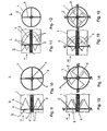
- FIG. 9 shows a further alternative embodiment for an air vent L.
- a device V for influencing the air flow is arranged, which is formed from a number of stiff, each about an associated axis 2 rotatable air guide elements 3.
- the air guide elements 3 are designed delta-shaped.
- a delta-shaped air guide element 3 is understood in particular to be triangular flaps or vortex generators.
- the axes 2 of the spoiler elements 3 are in the radial position on the longitudinal axis 4 of the air duct 1 and are attached to a central body 5.
- the air guiding elements 3 are aligned in the main flow direction H. As a result, the guided through the air duct 1 air flow is not affected. That is, the air guide elements 3 are in the operating position "Spot-shaped air outlet".
- the air guiding elements 3 are rotated synchronously with respect to the main flow direction H about their axes 2 and are therefore in the operating position "diffused air outlet".
- By controlled detachment arise at the oblique front edges of the respective air guide element 3 longitudinal swirls, which burst depending on the angle of attack after a certain length of run and so in addition to generated swirl Contribute to a fanning of the beam through increased momentum exchange.
- the further alternative embodiment for an air vent L shown in FIG. 13 has a device V for influencing the flow of air similar to that shown in FIG.
- the air guiding elements 3 are half-delta-shaped in the main flow direction H and delta-shaped in the opposite direction.
- the air-laying elements 3 are aligned in the main flow direction H, so that the air flow is not influenced by them. That the air guide elements 3 are in the operating position "Spot-shaped air outlet”.
- the air guide elements 3 are rotated synchronously with respect to the main flow direction H about their axes 2 and brought into such an end position that the semi-deltoid parts of the air guide elements 3 bear against the inner wall of the air channel 1.
- the spoiler elements 3 are thus in the operating position "Diffuser air outlet".
- the generation of swirls or eddies can be additionally improved in this way.
- the air duct 1 may alternatively have another geometric cross-sectional shape, e.g. a rectangular shape, have.
- rigid air guide elements 3 are preferably plastic or sheet used, when using flexible Lufleft implant 3 correspondingly soft and / or elastic plastics, rubber or thin spring steel.
- air vent L shown in various embodiments can be pivotally supported by means of a ball joint or gimbal.
- the air vortices and / or swirl can be generated by injection of tangential air flows into the air duct 1.
- air is introduced tangentially into the air duct 1 in a manner not shown, so that the already in the air duct 1 guided air flow is placed in a swirling motion.
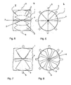
- FIG. 17 shows another embodiment of an air vent L, in which an inner air duct 1.1 is arranged in an outer air duct 1.2.
- the hydraulic diameters of the air channels 1.1, 1.2 are equal to each other.
- the cross sections of both air channels 1.1, 1.2 are circular.
- Each of the two air channels 1.1, 1.2 has its own device V for influencing the air flow, which is independently adjustable from that of the respective other air channel 1.2, 1.1.
- the device comprises four air guide elements 3, which are each rotatable about an associated axis 2. Aligned axes 2 of spoiler elements 3 different air channels 1-1, 1.2 stuck, for example, one inside the other.
- Figure 18 shows the same Lucasausströmer L in a longitudinal sectional view.
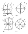
- FIGS. 19 to 22 show operating cases of the air vent L from FIG. 17.
- a directed, jet-shaped air outlet of one of the air ducts 1.1, 1.2 is symbolized by two circles arranged one inside the other, while a diffused air outlet with a swirl symbolizes it with a curved arrow.
- a combination of these operating cases of the individual air ducts 1.1, 1.2 results in a respectively different overall characteristic of the air outflow.
- both air channels 1.1, 1.2 are exposed to air.
- the air guide elements 3 of both air channels 1.1, 1.2 each occupy a position in which they do not affect the air flow.
- the air flows out of the air vent L jet-shaped and directed
- the characteristic of the air flow is called "spot" and is less sharp, but pronounced with higher throughput than in Figure 19.
- the outer air duct 1.2 can be used as a bypass to reduce pressure losses ,
- both air channels 1.1, 1.2 are exposed to air.
- the air guide elements 3 of both air channels 1.1, 1.2 each occupy a position in which they twist the air flow, in such a way that the direction of rotation of the twisting of the outer air duct 1.2 is directed counter to that of the inner air duct 1-1.
- the air from the air vent L flows out particularly diffusely.
- the characteristic of the air flow is called "diffuse with counter-rotation".
- both air channels 1.1, 1.2 are exposed to air.
- the spoilers 3 of the outer air duct 1.2 occupy a position in which they twist the air flow, the inner air duct 1.1, however, do not affect the air flow.
- the characteristic of the air flow is called "spot-diffuse".
- Air channels 1.1, 1.2 and 3 air guide elements may have a different shape from the one shown.
- the Luftausströmer shown in Figures 17 to 22 can be designed to be pivotable.
- flexible and / or twistable air guide elements 3 can be used.
- rigid air guide elements 3 are preferably plastic or sheet used, when using flexible air guide 3 according to soft and / or elastic plastics, rubber or thin spring steel.
- the air vortices and / or swirl can be generated by injecting tangential air flows into the air ducts 1.1, 1.2.
Landscapes
- Engineering & Computer Science (AREA)
- Mechanical Engineering (AREA)
- Physics & Mathematics (AREA)
- Thermal Sciences (AREA)
- Chemical & Material Sciences (AREA)
- Combustion & Propulsion (AREA)
- General Engineering & Computer Science (AREA)
- Air-Flow Control Members (AREA)
- Air-Conditioning For Vehicles (AREA)
Applications Claiming Priority (1)
| Application Number | Priority Date | Filing Date | Title |
|---|---|---|---|
| DE102005052934 | 2005-11-03 |
Publications (2)
| Publication Number | Publication Date |
|---|---|
| EP1782977A1 true EP1782977A1 (fr) | 2007-05-09 |
| EP1782977B1 EP1782977B1 (fr) | 2009-12-16 |
Family
ID=37562141
Family Applications (1)
| Application Number | Title | Priority Date | Filing Date |
|---|---|---|---|
| EP20060022391 Not-in-force EP1782977B1 (fr) | 2005-11-03 | 2006-10-26 | Buse d'air |
Country Status (2)
| Country | Link |
|---|---|
| EP (1) | EP1782977B1 (fr) |
| DE (1) | DE502006005652D1 (fr) |
Cited By (2)
| Publication number | Priority date | Publication date | Assignee | Title |
|---|---|---|---|---|
| DE102010001811A1 (de) | 2010-02-11 | 2011-08-11 | Behr GmbH & Co. KG, 70469 | Luftausströmer |
| CN114872517A (zh) * | 2022-05-26 | 2022-08-09 | 奇瑞汽车股份有限公司 | 汽车空调的扫风结构 |
Citations (4)
| Publication number | Priority date | Publication date | Assignee | Title |
|---|---|---|---|---|
| DE2902733A1 (de) * | 1979-01-25 | 1980-08-07 | Kessler & Luch Gmbh | Luft-drallauslass fuer klimaanlagen |
| DE3736448A1 (de) * | 1987-10-28 | 1989-05-11 | Ltg Lufttechnische Gmbh | Luftdrallauslass und verfahren zu seinem betreiben |
| DE102004011352A1 (de) * | 2003-03-13 | 2004-09-23 | Behr Gmbh & Co. Kg | Luftausströmer, insbesondere für ein Kraftfahrzeug und ein zugehöriges Luftausströmverfahren |
| DE10341735A1 (de) * | 2003-09-08 | 2005-03-31 | Behr Gmbh & Co. Kg | Luftausströmer, insbesondere für ein Kraftfahrzeug |
-
2006
- 2006-10-26 EP EP20060022391 patent/EP1782977B1/fr not_active Not-in-force
- 2006-10-26 DE DE200650005652 patent/DE502006005652D1/de active Active
Patent Citations (4)
| Publication number | Priority date | Publication date | Assignee | Title |
|---|---|---|---|---|
| DE2902733A1 (de) * | 1979-01-25 | 1980-08-07 | Kessler & Luch Gmbh | Luft-drallauslass fuer klimaanlagen |
| DE3736448A1 (de) * | 1987-10-28 | 1989-05-11 | Ltg Lufttechnische Gmbh | Luftdrallauslass und verfahren zu seinem betreiben |
| DE102004011352A1 (de) * | 2003-03-13 | 2004-09-23 | Behr Gmbh & Co. Kg | Luftausströmer, insbesondere für ein Kraftfahrzeug und ein zugehöriges Luftausströmverfahren |
| DE10341735A1 (de) * | 2003-09-08 | 2005-03-31 | Behr Gmbh & Co. Kg | Luftausströmer, insbesondere für ein Kraftfahrzeug |
Cited By (3)
| Publication number | Priority date | Publication date | Assignee | Title |
|---|---|---|---|---|
| DE102010001811A1 (de) | 2010-02-11 | 2011-08-11 | Behr GmbH & Co. KG, 70469 | Luftausströmer |
| DE102010001811B4 (de) | 2010-02-11 | 2019-05-16 | Mahle International Gmbh | Luftausströmer und Kraftfahrzeugklimaanlage |
| CN114872517A (zh) * | 2022-05-26 | 2022-08-09 | 奇瑞汽车股份有限公司 | 汽车空调的扫风结构 |
Also Published As
| Publication number | Publication date |
|---|---|
| DE502006005652D1 (de) | 2010-01-28 |
| EP1782977B1 (fr) | 2009-12-16 |
Similar Documents
| Publication | Publication Date | Title |
|---|---|---|
| EP1972476B1 (fr) | Extracteur d'air avec écoulement giratoire et flux dirigé | |
| EP2139709B1 (fr) | Aérateur à écoulement turbulent et écoulement classique | |
| EP1923242B1 (fr) | Dispositif d'écoulement d'air avec écoulement giratoire et écoulement conventionnel | |
| EP1656271B1 (fr) | Systeme d'echappement d'air, notamment pour une automobile | |
| DE102007018022C5 (de) | Luftdüse | |
| EP1826043B1 (fr) | Tuyère d'air | |
| EP1800918B1 (fr) | Buse d'air à écoulement tourbillonnant | |
| EP1608522B1 (fr) | Dispositif d'evacuation d'air, en particulier pour un vehicule et procede d'evacuation d'air correspondant | |
| EP1785298B1 (fr) | Buse d'air | |
| DE102009050885A1 (de) | Luftausströmer | |
| DE102004039950A1 (de) | Luftleitvorrichtung, insbesondere für den Innenraum von Fahrzeugen | |
| EP1747109B1 (fr) | Ejecteur d'air, notamment pour automobile | |
| EP2117860B1 (fr) | Aérateur, notamment pour un véhicule automobile | |
| DE102006050999A1 (de) | Luftausströmer | |
| DE102008005985B4 (de) | Luftausströmer | |
| EP1782977B1 (fr) | Buse d'air | |
| DE102024003513A1 (de) | Belüftungseinrichtung für einen Kraftwagen sowie Verfahren | |
| DE102015206621A1 (de) | Luftstromsteuereinheit | |
| DE102012204555A1 (de) | Luftausströmer | |
| DE102011075977A1 (de) | Komfortdüse | |
| EP1810855A1 (fr) | Aérateur, en particulier pour un système de ventilation d'un véhicule | |
| DE102006017376A1 (de) | Luftzuführungskanal | |
| EP2261067B1 (fr) | Dispositif d'écoulement d'air | |
| EP1740402B1 (fr) | Dispositif d'aeration pour vehicule | |
| DE102015206609A1 (de) | Luftstromsteuereinheit |
Legal Events
| Date | Code | Title | Description |
|---|---|---|---|
| PUAI | Public reference made under article 153(3) epc to a published international application that has entered the european phase |
Free format text: ORIGINAL CODE: 0009012 |
|
| AK | Designated contracting states |
Kind code of ref document: A1 Designated state(s): AT BE BG CH CY CZ DE DK EE ES FI FR GB GR HU IE IS IT LI LT LU LV MC NL PL PT RO SE SI SK TR |
|
| AX | Request for extension of the european patent |
Extension state: AL BA HR MK YU |
|
| RIN1 | Information on inventor provided before grant (corrected) |
Inventor name: LANG, MATTHIAS, DR. |
|
| 17P | Request for examination filed |
Effective date: 20071109 |
|
| 17Q | First examination report despatched |
Effective date: 20071213 |
|
| AKX | Designation fees paid |
Designated state(s): DE ES FR IT SE |
|
| GRAP | Despatch of communication of intention to grant a patent |
Free format text: ORIGINAL CODE: EPIDOSNIGR1 |
|
| GRAS | Grant fee paid |
Free format text: ORIGINAL CODE: EPIDOSNIGR3 |
|
| GRAA | (expected) grant |
Free format text: ORIGINAL CODE: 0009210 |
|
| AK | Designated contracting states |
Kind code of ref document: B1 Designated state(s): DE ES FR IT SE |
|
| REF | Corresponds to: |
Ref document number: 502006005652 Country of ref document: DE Date of ref document: 20100128 Kind code of ref document: P |
|
| PG25 | Lapsed in a contracting state [announced via postgrant information from national office to epo] |
Ref country code: SE Free format text: LAPSE BECAUSE OF FAILURE TO SUBMIT A TRANSLATION OF THE DESCRIPTION OR TO PAY THE FEE WITHIN THE PRESCRIBED TIME-LIMIT Effective date: 20091216 |
|
| PG25 | Lapsed in a contracting state [announced via postgrant information from national office to epo] |
Ref country code: ES Free format text: LAPSE BECAUSE OF FAILURE TO SUBMIT A TRANSLATION OF THE DESCRIPTION OR TO PAY THE FEE WITHIN THE PRESCRIBED TIME-LIMIT Effective date: 20100327 |
|
| PLBE | No opposition filed within time limit |
Free format text: ORIGINAL CODE: 0009261 |
|
| STAA | Information on the status of an ep patent application or granted ep patent |
Free format text: STATUS: NO OPPOSITION FILED WITHIN TIME LIMIT |
|
| 26N | No opposition filed |
Effective date: 20100917 |
|
| PG25 | Lapsed in a contracting state [announced via postgrant information from national office to epo] |
Ref country code: IT Free format text: LAPSE BECAUSE OF FAILURE TO SUBMIT A TRANSLATION OF THE DESCRIPTION OR TO PAY THE FEE WITHIN THE PRESCRIBED TIME-LIMIT Effective date: 20091216 |
|
| PGFP | Annual fee paid to national office [announced via postgrant information from national office to epo] |
Ref country code: FR Payment date: 20111026 Year of fee payment: 6 |
|
| REG | Reference to a national code |
Ref country code: FR Ref legal event code: ST Effective date: 20130628 |
|
| PG25 | Lapsed in a contracting state [announced via postgrant information from national office to epo] |
Ref country code: FR Free format text: LAPSE BECAUSE OF NON-PAYMENT OF DUE FEES Effective date: 20121031 |
|
| REG | Reference to a national code |
Ref country code: DE Ref legal event code: R082 Ref document number: 502006005652 Country of ref document: DE Representative=s name: GRAUEL, ANDREAS, DIPL.-PHYS. DR. RER. NAT., DE |
|
| REG | Reference to a national code |
Ref country code: DE Ref legal event code: R081 Ref document number: 502006005652 Country of ref document: DE Owner name: MAHLE INTERNATIONAL GMBH, DE Free format text: FORMER OWNER: BEHR GMBH & CO. KG, 70469 STUTTGART, DE Effective date: 20150226 Ref country code: DE Ref legal event code: R082 Ref document number: 502006005652 Country of ref document: DE Representative=s name: GRAUEL, ANDREAS, DIPL.-PHYS. DR. RER. NAT., DE Effective date: 20150226 |
|
| PGFP | Annual fee paid to national office [announced via postgrant information from national office to epo] |
Ref country code: DE Payment date: 20181030 Year of fee payment: 13 |
|
| REG | Reference to a national code |
Ref country code: DE Ref legal event code: R119 Ref document number: 502006005652 Country of ref document: DE |
|
| PG25 | Lapsed in a contracting state [announced via postgrant information from national office to epo] |
Ref country code: DE Free format text: LAPSE BECAUSE OF NON-PAYMENT OF DUE FEES Effective date: 20200501 |