EP1783068B1 - Fördervorrichtung mit einer sich hebenden/senkenden lastplattform - Google Patents
Fördervorrichtung mit einer sich hebenden/senkenden lastplattform Download PDFInfo
- Publication number
- EP1783068B1 EP1783068B1 EP05768345A EP05768345A EP1783068B1 EP 1783068 B1 EP1783068 B1 EP 1783068B1 EP 05768345 A EP05768345 A EP 05768345A EP 05768345 A EP05768345 A EP 05768345A EP 1783068 B1 EP1783068 B1 EP 1783068B1
- Authority
- EP
- European Patent Office
- Prior art keywords
- platform
- operated portion
- conveying
- cam
- crosslink
- Prior art date
- Legal status (The legal status is an assumption and is not a legal conclusion. Google has not performed a legal analysis and makes no representation as to the accuracy of the status listed.)
- Expired - Lifetime
Links
Images


Classifications
-
- B—PERFORMING OPERATIONS; TRANSPORTING
- B66—HOISTING; LIFTING; HAULING
- B66F—HOISTING, LIFTING, HAULING OR PUSHING, NOT OTHERWISE PROVIDED FOR, e.g. DEVICES WHICH APPLY A LIFTING OR PUSHING FORCE DIRECTLY TO THE SURFACE OF A LOAD
- B66F7/00—Lifting frames, e.g. for lifting vehicles; Platform lifts
- B66F7/06—Lifting frames, e.g. for lifting vehicles; Platform lifts with platforms supported by levers for vertical movement
- B66F7/065—Scissor linkages, i.e. X-configuration
-
- B—PERFORMING OPERATIONS; TRANSPORTING
- B62—LAND VEHICLES FOR TRAVELLING OTHERWISE THAN ON RAILS
- B62D—MOTOR VEHICLES; TRAILERS
- B62D65/00—Designing, manufacturing, e.g. assembling, facilitating disassembly, or structurally modifying motor vehicles or trailers, not otherwise provided for
- B62D65/02—Joining sub-units or components to, or positioning sub-units or components with respect to, body shell or other sub-units or components
- B62D65/18—Transportation, conveyor or haulage systems specially adapted for motor vehicle or trailer assembly lines
-
- B—PERFORMING OPERATIONS; TRANSPORTING
- B65—CONVEYING; PACKING; STORING; HANDLING THIN OR FILAMENTARY MATERIAL
- B65G—TRANSPORT OR STORAGE DEVICES, e.g. CONVEYORS FOR LOADING OR TIPPING, SHOP CONVEYOR SYSTEMS OR PNEUMATIC TUBE CONVEYORS
- B65G17/00—Conveyors having an endless traction element, e.g. a chain, transmitting movement to a continuous or substantially-continuous load-carrying surface or to a series of individual load-carriers; Endless-chain conveyors in which the chains form the load-carrying surface
- B65G17/30—Details; Auxiliary devices
- B65G17/48—Controlling attitudes of load-carriers during movement
-
- B—PERFORMING OPERATIONS; TRANSPORTING
- B65—CONVEYING; PACKING; STORING; HANDLING THIN OR FILAMENTARY MATERIAL
- B65G—TRANSPORT OR STORAGE DEVICES, e.g. CONVEYORS FOR LOADING OR TIPPING, SHOP CONVEYOR SYSTEMS OR PNEUMATIC TUBE CONVEYORS
- B65G7/00—Devices for assisting manual moving or tilting heavy loads
- B65G7/02—Devices adapted to be interposed between loads and the ground or floor, e.g. crowbars with means for assisting conveyance of loads
Definitions
- the present invention relates to a conveying apparatus formed so as to selectively move a platform supported on a conveying traveler body so as to be liftable and lowerable via erectable crosslinks to a lifted position by a cam rail laid down on the side of a conveying route.
- Patent Literature 1 Japanese Published Unexamined Patent Application No. H07-172538 , disclosing the preamble of claim 1
- a lifting stroke of the platform can be make greater than a lifting stroke of the lifting/lowering member by providing a thrusting operation position by the lifting/lowering member on the crosslinks at a center crossover fulcrum position of the crosslinks or closer to a link fulcrum position on the conveying traveler body side than the center crossover fulcrum position.
- the lifting stroke of the lifting/lowering member must be correspondingly increased.
- a conveying apparatus in which a platform (3) is supported on a conveying traveler body (1) so as to be so as to be freely liftable and lowerable via a erectable crosslink (13a), and a first cam rail (47A) and a second cam rail (48) is laid down, the first cam rail (47A) that works on a first to-be-operated portion (28) provided concurrently with the crosslink (13a) and protruded to the downside of the conveying traveler body (1) so as to lift the platform (3) to a middle height (H1), and a second cam rail (48) that works on a second to-be-operated portion (29) provided concurrently with the crosslink (13a) and protruded to a downside of the conveying traveler body (1) so as to lift the platform (3) from the middle height (H1)
- the first to-be-operated portion (28) can be composed of a cam follower roller (31a) that is supported by a protruded portion (30a) continuously provided downward from the link (14a) of the crosslink (13a) and is directly pushed up by the first cam rail (47A).
- the second to-be-operated portion (29) can be composed of a cam follower roller (33) that is supported by concentrically with the middle bending fulcrum (36) of the toggle link (32) and is directly pushed up by the second cam rail (48).
- the configuration can be combined with the configuration according to the second aspect of the invention.
- the first to-be-operated portion (28) can be composed of a pair of right and left cam follower rollers (31a and 31b) that are respectively directly pushed up by the juxtaposed two first cam rails (47A) supported by protruding portions (30a and 30b) continuously provided downward from inside links (14a and 15a) of the respective crosslinks (13a and 13b), and the toggle link (32) provided with the second to-be-operated portion (29) can be interposed between a center portion of a hanging member (37) provided so as to hang between the inside links (14a and 15b) of the respective crosslinks (13a and 13b) and a fixing position on the conveying traveler body (1) side, and the single second cam rail (48) that works on the second to-be-operated portion (29) can be disposed at a middle position between the
- a locking means (40) that prevents from carrying out a falling motion of the crosslink (13a) in which the platform (3) is lifted to the maximum height (H2) by the second cam rail (47A) and the second to-be-operated portion (29) can be provided concurrently with the crosslink (13a).
- the configuration can be combined with the configuration according to any one of the second to fourth aspects of the invention.
- the locking means (40) can be composed of a latch (42) that is automatically latched with a to-be-latched portion (41) provided at a slide fulcrum position (25) on the conveying traveler body (1) side of the crosslink (13a) or in a vicinity thereof.
- the platform is lifted to the maximum objective height by pushing up the same in two stages by use of the first to-be-operated portion and the first cam rails and the second to-be operated portion and the second cam rail.
- first to-be-operated portion and the first cam rails it is satisfactory for the first to-be-operated portion and the first cam rails that these can make the crosslinks stand up until a condition where the second to-be-operated portion provided in the vicinity of the middle bending fulcrum of the toggle link can be thrust up by the second cam rail, namely, until the toggle link collapsed into a condition where the upper both-end fulcrums are located at either front or rear side in the traveling direction with respect to the middle bending fulcrum reaches an extended condition where the upper both-end fulcrums are separated at the front and rear in the traveling direction with respect to the middle bending fulcrum, and a lifting stroke of the platform by the first to-be-operated portion and the first cam rails may be sufficiently small in comparison with the total stroke to the maximum objective height.
- the height of the second to-be-operated portion provided concurrently with the toggle link has hardly been changed from the height when the crosslinks are in a fallen condition (when the platform is located at the lowering limit height) and the second-to-be-operated portion is located sufficiently lower than the first to-be-operated portion pushed up by the first cam rails. Therefore, with the height of the second cam rail that pushes up the second to-be-operated portion being made almost identical to the height of the first cam rails, the platform can be lifted from the middle height to the higher maximum height via the toggle link.
- the maximum height of the platform can be provided as a sufficient height as needed.
- such a layout as to lay down only the first cam rails in a specific section of the conveying route so as to use the platform in a manner lifted to the middle height and lay down both the first and second cam rails in the other specific section so as to use the platform in a manner lifted to the maximum height can also be employed.
- the present invention can be simply carried out at a low cost.
- the crosslinks that support the platform so as to be freely liftable and lowerable are generally provided side by side as a pair of right and left crosslinks so that the respective fulcrums are concentric with each other.
- the platform can be strongly pushed up to the middle height without difficulty by the two right and left first cam rails in a first pushing-up stage where a great pushing-up force is necessary, that is, a first push-up stage where the platform is lifted to the middle height by the first to-be-operated portion and the first cam rails, and in a second pushing-up stage where a smaller pushing-up force is sufficient in comparison with that in the first pushing-up stage, that is, a second pushing-up stage where the platform is lifted to the maximum height by the second to-be-operated portion and the second cam rail, the platform can be lifted to the maximum height in a well-balanced manner by pushing up a center position between the pair of right and left crosslinks by the single second cam rail.
- the locking means be carried out with a simple configuration, but also no special locking operation or control is necessary when the platform has been lifted to the highest position, so that the present invention can be carried out at a low cost.
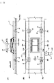
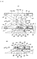
- FIGS. 1 exemplify a basic configuration of a friction-drive type conveying apparatus with a freely liftable and lowerable platform.
- Reference numeral 1 denotes a flat rectangular carriage-type conveying traveler body along a traveling direction, which is equipped with two front and rear sets of right and left pairs of wheel units 2a to 2d and a freely liftable and lowerable platform 3.
- the respective wheel units 2a to 2d have wheels 5 that roll on a pair of right and left guide rails 4a and 4b laid down along a conveying route, and in the two front and rear wheel units 2a and 2c on one of the right and left sides (in the illustrated example, left side), anti-vibration vertical axis rollers 6 that sandwich the guide rail 4a from both right and left sides are provided.
- the conveying traveler body 1 is propelled by a friction drive means 7 concurrently provided at an appropriate point of the conveying route .
- the friction drive means 7 is conventionally well known and composed of a drive friction wheel 9 that abuts on one friction surface 8a of a pair of right and left vertical friction surfaces 8a and 8b in parallel formed on the conveying traveler body 1 across the overall length thereof, a motor 10 for rotary drive of the drive friction wheel 9, and a backup roller 11 that abuts on the other friction surface 8b so as to sandwich the conveying traveler body 1 between the same and drive friction wheel 9.
- the friction drive means 7 has been exemplified as a means for propelling the conveying traveler body 1, a propelling means by any other method may be employed, such as driving at least one of the wheels 5 by a motor, or engaging a drive chain provided in a tensioned state so as to move along the conveying route of the conveying traveler body 1 with the conveying traveler body 1 and propelling the conveying traveler body 1 by the drive chain.
- a propelling means by any other method may be employed, such as driving at least one of the wheels 5 by a motor, or engaging a drive chain provided in a tensioned state so as to move along the conveying route of the conveying traveler body 1 with the conveying traveler body 1 and propelling the conveying traveler body 1 by the drive chain.
- both right and left side surfaces of the conveying traveler body 1 may be diverted as they are, or other members may be attached.
- the conveying device may be one in which platforms 3 are disposed at appropriate intervals on a conveying traveler body 1 that continues in the conveying route direction, as in a slat conveyer.
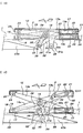
- the platform 3 is a table to support a to-be-carried object, and is supported so as to be vertically movably by a crosslink mechanism 12 interposed between the same and conveying traveler body 1 under the platform 3.
- This crosslink mechanism 12 is composed of two crosslinks 13a and 13b in parallel with the conveying route juxtaposed to each other under the platform 3.
- the crosslink mechanism 12 comprises a pair of right and left crosslinks 13a and 13b which includes two pairs of links 14a and 14b, and 15a and 15b whose center crossover portions are pivotally mounted at mutually concentric center fulcrum shafts 16, and of the links 14a to 15b provided two each, front end portions of both links 14a and 15a to be located inside are pivotally mounted so as to be freely swingable up and down by mutually concentric position fixing fulcrum shafts 19 on a pair of right and left bearing members 18 provided on a support frame 17 on the conveying traveler body 1 side.
- both links 14a and 15a are coupled by a common slide fulcrum shaft 20, and rollers 21 supported by both sides of the common slide fulcrum shaft 20 are fitted with a pair of right and left back-and-forth slide guides 22 provided on the downside of a rear end portion of the platform 3 so as to be rollable in the back and forth direction.
- front end portions of both links 14b and 15b to be located outside are pivotally mounted so as to be freely swingable up and down by mutually concentric position fixing fulcrum shafts 24 on a pair of right and left bearing members 23 provided, on the downside of a front end portion of the platform 3, at a position directly above the pair of right and left bearing portions 18.
- Rear end portions of both links 14b and 15b are coupled by a common slide fulcrum shaft 25, and rollers 26 removably supported on both ends of the common slide fulcrum shaft 25 are fitted with a pair of right and left back-and-forth slide guides 27 provided, on the support frame 17 on the conveying traveler body 1 side, at a position directly below the back-and-forth slide guide 22 so as to be rollable in the back and forth direction.
- first to-be-operated portion 28 is composed of cam follower rollers 31a and 31b supported by right and left horizontal shafts mutually concentric with the lower ends of protruding portions 30a and 30b continuously provided downward from both links 14a and 15a to be located inside of the links 14a to 15b provided two each to compose the pair of right and left crosslinks 13a and 13b.
- the protruding portions 30a and 30b are continuously provided downward, in a middle position between the center fulcrum shafts 16 of both links 14a and 15a and the common slide fulcrum shaft 20, from a position close to the center fulcrum shafts 16, and are structured so that, when the platform 3 is at a lowering limit height as shown in FIG. 2 , the cam follower rollers 31a and 31b are located at a position close to the floor in a manner protrudeddownward from the conveying traveler body 1.
- the second to-be-operated portion 29 is composed of one cam follower roller 33 supported by a toggle link 32 concurrently provided in the crosslink mechanism 12.
- the toggle link 32 is formed by coupling a long link 34 and a short link 35 with each other at a middle bending fulcrum shaft 36.
- the respective links 34 and 35 are composed of pairs of right and left link units 34a and 34b and 35a and 35b, respectively, and the cam follower roller 33 is removably supported by the middle bending fulcrum shaft 36 between link units 34a and 34b of the long link 34 to be located inside.
- the toggle link 32 is arranged roughly in the center between the pair of right and left crosslinks 13a and 13b.
- a free end of the long link 34 is pivotally mounted, in a middle position between the center fulcrum shafts 16 of inside both links 14a and 15a to compose the crosslinks 13a and 13b and the common slide fulcrum shaft 20, by a shaft-like hanging member (spindle member) 37 provided so as to hang between the links 14a and 15a in the right and left horizontal direction.
- a free end of the short link 35 is pivotally mounted on a bearing member 38 provided as an annex on the support frame 17 on the conveying traveler body 1 side by a spindle 39 located below the center fulcrum shafts 16 of the crosslinks 13a and 13b.
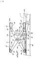
- a locking means 40 that supports the platform 3 at a maximum height can be concurrently provided.
- the locking means 40 includes a pair of right and left latches 42 that use, as to-be-latched portions 41, the common slide fulcrum 25 provided to hang between the outside both links 14a and 15b to compose the crosslinks 13a and 13b and are automatically latched with the to-be-latched portions 41.
- the respective latches 42 are of an identical structure arranged with respect to the second to-be-operated portion 29 in a condition separated at the right and left so as to be located in the middle between the pair of right and left cam follower rollers 31a and 31b of the first to-be-operated portion 28 and single cam follower roller 33 of the second to-be-operated portion 29. These are respectively supported by the horizontal spindles 44 mutually concentric with bearing members 43 provided on the support frame 17 on the conveying traveler body 1 side so as to be freely swingable up and down, and abutting members 45 annexed to the respective latches 42 are held by gravity at home positions to be caught by the bearing members 43 .
- arm portions 42a are integrally provided downward in connected row arrangements, and on the lower ends of the arm portions 42a, cam follower rollers 46 are supported via mutually concentric right and left horizontal spindles.
- the cam follower rollers 46 are protruded downward further than the bottom surface of the conveying traveler body 1.
- the platform 3 is normally stable by gravity in a condition lowered to a lowering limit height shown in FIG. 2 .
- the lowering limit height of the platform 3 can be determined by a height-adjustable support tool (which is conventionally well known, and illustration is omitted) provided in a standing condition on the conveying traveler body 1 side.
- a height-adjustable support tool which is conventionally well known, and illustration is omitted
- the pair of right and left crosslinks 13a and 13b of the crosslink mechanism 12 are in a fallen condition as shown in FIG. 2 , and the pair of right and left cam follower rollers 31a and 31b of the first to-be-operated portion 28 are protruded from the bottom surface of the conveying traveler body 1 at the maximum.
- the cam follower roller 33 of the second to-be-operated portion 29 is at an almost identical level as that of the cam follower rollers 31a and 31b of the first to-be-operated portion 28, and the toggle link 32 equipped with the cam follower roller 33 is collapsed so that the free-end fulcrums (hanging member (spindle member) 37 and spindle 39) of both links 34 and 35 all are located backward in the traveling direction of the conveying traveler body 1 relative to the cam follower roller 33. Accordingly, in this condition, it is impossible to push up the cam follower roller 33 upward so as to make the crosslinks 13a and 13b stand up.
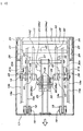
- a pair of right and left end-side first cam rails 47B that accept the descending pair of right and left cam follower rollers 31a and 31b of the first to-be-operated portion 28 and then allow the cam follower rollers 31a and 31b to descend as a result of a forward travel of the conveying traveler body 1 are laid down, and furthermore, in the specific section from the vicinity of end portions of the start-side first cam rails 47A to the vicinity of start portions of the end-side first cam rails 47B, a second cam rail 48 that pushes up the cam follower roller 33 of the second to-be-operated portion 29 as a result of a forward travel of the conveying traveler body 1 and holds the same at a predetermined height is laid down.
- the pair of right and left cam follower rollers 31a and 31b of the first to-be-operated portion 28 gradually ride on the pair of right and left start-side first cam rails 47A as shown in FIG. 3 , and the pair of right and left start-side first cam rails 47A thrust up the inside links 14a and 15a of the pair of right and left crosslinks 13a and 13b via the pair of right and left cam follower rollers 31a and 31b. Accordingly, the pair of right and left crosslinks 13a and 13b carry out a standing motion in conjunction with each other, so that the platform 3 supported by the pair of right and left crosslinks 13a and 13b rises while maintaining a horizontal posture.
- the platform 3 reaches a predetermined middle height H1, however, with the standing motion of the crosslinks 13a and 13b during the time where the platform 3 is lifted from the lowering limit height to the middle height H1, the toggle link 32 is slightly extended into a V-shape from the collapsed condition shown in FIG.
- the cam follower roller 33 moves rearward at an almost identical level, resulting in a condition where the free-end fulcrums (hanging member (spindle member) 37 and spindle 39) of the toggle links 32 are arranged with respect to the cam follower roller 33 in a condition separated at the front and rear. Therefore, in this condition, by pushing up the cam follower rollers 33, the toggle link 32 can further be extended so as to make the crosslinks 13a and 13b carry out a standing motion.
- the second cam rail 48 is laid down so that the cam follower roller 33 of the second to-be-operated portion 29 starts to ride on the second cam rail 48 during the time where the cam follower rollers 31a and 31b are rolling on the highest flat surfaces of the start-side first cam rails 47A.
- the highest flat surfaces may be substantially eliminated from the start-side first cam rails 47A so that the cam follower roller 33 of the second to-be-operated portion 29 starts to ride on the second cam rail 48 immediately before the cam follower rollers 31a and 31b leave the highest positions of the start-side first cam rails 47A.
- the lower common slide fulcrum 25 passes while pushing up the pair of right and left latches 42 via inclined surfaces on the downside of the front ends thereof immediately before the platform 3 reaches the maximum height H2, and when the platform 3 has reached the maximum height H2, that is, when the cam follower roller 33 of the second to-be-operated portion 29 has reached the highest flat surface of the second cam rail 48, concave latching portions 42b of the pair of right and left latches 42 are fitted and latched with the lower common slide fulcrum shaft 25 (to-be-latched portions 41) from upside by gravity.
- springs that forcedly charge the respective latches 42 downward may be used together.
- the locking means 40 when the conveying traveler body 1 enters the specific section, the platform 3 that has been located at the lowering limit height is automatically lifted to the maximum height H2.
- the latches 42 of the locking means 40 are automatically latched with the to-be-latched portions 41 (lower common slide fulcrum shaft 25) of the crosslinks 13a and 13b so as to prevent the pair of right and left crosslinks 13a and 13b in a standing condition from carrying out a falling motion.
- the concave latching portions 42b of both latches 42 fitted with the common slide fulcrum shaft 25 (to-be-latched portions 41) prevents a rearward slide of the common slide fulcrum shaft 25 (to-be-latched portions 41) of the closslinks 13a and 13b in a standing condition when the platform 3 is lowered from the maximum height H2. Therefore, even if the toggle link 32 that supports the cam follower roller 33 that has been pushed up by the second cam rail 4 8 is bent or broken during the time the conveying traveler body 1 is traveling in the specific section where the platform 3 is kept lifted to the maximum height, the platform 3 can be prevented from falling down from the maximum height H2.
- unlocking cams 49 are laid down.
- the unlocking cams 49 are arranged on both right and left sides of the second cam rail 48 in a manner corresponding to the respective latches 42 so that the cam follower rollers 46 of the latches 42 ride thereon as the conveying traveler body 1 travels.
- the cam follower rollers 46 ride on the unlocking cams 49 so as to swing the latches 42 upward against gravity, the concave latching portions 42b of the latches 42 are separated upward from the common slide fulcrum shaft 25 (to-be-latched portions 41) of the crosslinks 13a and 13b, so that a lock to the crosslinks 13a and 13b in a standing condition is released.
- the conveying traveler body 1 After the unlocking operation described above, the conveying traveler body 1 reaches the end portion of the specific section, and the cam follower roller 33 of the second to-be-rotated portion 29 is ready to descend down an end downhill slope portion of the second cam rail 48 as the conveying traveler body 1 travels, so that the platform 3 is lowered while making the crosslinks 13a and 13b carry out a falling motion by gravity. Therefore, as shown in Fig.
- a first specific section where the platform 3 is kept lifted to the maximum height H2 and a second specific section where the platform 3 is kept lifted to the middle height H1 can be provided.
- the first specific section as in the embodiment and connecting, in the second specific section, the pair of right and left start-side first cam rails 47A and the pair of right and left end-side first cam rails 47B across the entire area of the second specific section, a condition where the platform 3 is pushed up to the intermediate height by the pair of right and left cam follower rollers 31a and 31b of the to-be-operated portion 28 can be maintained across the entire area of the second specific section.
- the pair of right and left crosslinks 13a and 13b have been used, it is also possible to support the platform 3 freely so as to be liftable and lowerable by only one crosslink with broad width. In other words, the number of crosslinks that support one platform 3 is not limited.
- a to-be-operated portion formed of a lifting/lowering member that thrusts up the crosslinks by rising so as to make the same stand up may be used.
- the conveying apparatus can be utilized, on an automobile assembly line, as a conveying apparatus carrying a vehicle body (carried object) to which various parts are attached while mounting the same on a platform 3 and keeping, in a section of a parts fitting operation (specific section described in the embodiment where the second cam rail 48 has been laid down), the vehicle body (platform 3) lifted to a level where an operator on the conveying traveler body 1 can easily carry out a parts fitting operation.
Landscapes
- Engineering & Computer Science (AREA)
- Mechanical Engineering (AREA)
- Transportation (AREA)
- Geology (AREA)
- Structural Engineering (AREA)
- Manufacturing & Machinery (AREA)
- Chemical & Material Sciences (AREA)
- Combustion & Propulsion (AREA)
- Life Sciences & Earth Sciences (AREA)
- Automobile Manufacture Line, Endless Track Vehicle, Trailer (AREA)
- Loading Or Unloading Of Vehicles (AREA)
- Handcart (AREA)
- Intermediate Stations On Conveyors (AREA)
- Warehouses Or Storage Devices (AREA)
- Auxiliary Methods And Devices For Loading And Unloading (AREA)
- Movable Scaffolding (AREA)
- Forklifts And Lifting Vehicles (AREA)
Claims (6)
- Zuführvorrichtung mit einer Anhebe-/Absenkplattform, bei der eine Plattform (3) an einem zuführenden Fortbewegungskörper (1) so abgestützt ist, dass sie frei über einen erigierbaren Scherenmechanismus (13a) anhebbar und absenkbar ist, und mit einer ersten Nockenschiene (47A), die auf einen ersten zu betätigenden Abschnitt (28) einwirkt, der zusammen mit dem Scherenmechanismus (13a) vorgesehen ist, welche zu einer Unterseite des zuführenden Fortbewegungskörpers (1) hervorsteht, um die Plattform (2) bis zu einer mittleren Höhe (H1) anzuheben, dadurch gekennzeichnet, dass
eine zweite Nockenschiene (48), die auf einen zweiten zu betätigenden Abschnitt (29) einwirkt, zusammen mit dem Scherenmechanismus (13a) vorgesehen ist, welche zu einer Unterseite des zuführenden Fortbewegungskörpers (1) so hervorsteht, dass sie die Plattform (3) von der mittleren Höhe (H1) zu einer Maximalhöhe (H2) anhebt, wobei
der zweite zu betätigende Abschnitt (29) an einem mittleren Biegedrehpunkt eines Gelenkverbinders (32) zwischen einem Verbinder (14a) des Scherenmechanismus (13a) und einer Befestigungsposition auf der Seite des zuführenden Fortbewegungskörpers (1) oder benachbart dazu eingefügt ist, wobei der Gelenkverbinder (32) in einen Zustand kollabiert ist, in dem obere Drehpunkte (37 und 39) an beiden Enden entweder an der Vorder- oder Rückseite in einer Fortbewegungsrichtung bezüglich des mittleren Biegedrehpunkts angeordnet sind, wenn die Plattform (3) an einer Absenkungsbegrenzungshöhe angeordnet ist, und er ausgedehnt ist, wenn die Plattform (3) zu der mittleren Höhe (H1) angehoben wurde, sodass die oberen Drehpunkte (37 und 39) an beiden Enden einen Zustand erreichen, der an vorderen und hinteren beiden Seiten in der Fortbewegungsrichtung bezüglich dem mittleren Biegedrehpunkt (36) getrennt sind, und wobei der zweite zu betätigende Abschnitt (29) im ausgedehnten Zustand tiefer angeordnet ist als der erste zu betätigende Abschnitt (28) zu diesem Zeitpunkt. - Zuführvorrichtung mit einer Anhebe-/Absenkplattform nach Anspruch 1, bei der
der erste zu betätigende Abschnitt (28) aus einer Nockenfolgerolle (31a) besteht, die durch einen hervorstehenden Abschnitt (30a) abgestützt ist, der zusammen mit dem Verbinder (14a) des Scherenmechanismus (13a) nach unten vorgesehen ist und der direkt durch die erste Nockenschiene (47A) hochgedrückt wird. - Zuführvorrichtung mit einer Anhebe-/Absenkplattform nach Anspruch 1, bei der
der zweite zu betätigende Abschnitt (29) aus einer Nockenfolgerolle (33a) besteht, die konzentrisch mit dem mittleren Biegedrehpunkt (36) des Gelenkverbinders (32) abgestützt ist und sie direkt durch die zweite Nockenschiene (48) hochgedrückt wird. - Zuführvorrichtung mit einer Anhebe-/Absenkplattform nach Anspruch 1, bei der
die Scherenmechanismen Seite an Seite als ein Paar aus rechten und linken Scherenmechanismen bereitgestellt sind, sodass jeweilige Drehpunkte konzentrisch zueinander sind, wobei der erste zu betätigende Abschnitt (28) aus einem Paar aus rechten und linken Nockenfolgerollen (31a und 31b) besteht, die jeweils direkt durch nebeneinander angeordnete zwei erste Nockenschienen (47A) hochgedrückt werden und die durch vorstehende Abschnitte (30a und 30b) abgestützt werden, die kontinuierlich nach unten von inneren Verbindern (14a, 15a) der jeweiligen Scherenmechanismen (13a und 13b) bereitgestellt sind, und bei welcher der Gelenkverbinder (32), der mit dem zweiten zu betätigenden Abschnitt (29) versehen ist, zwischen einem Mittelabschnitt eines Hängeelements (37), das so vorgesehen ist, dass es zwischen den inneren Verbindern (14a und 15b) der jeweiligen Scherenmechanismen (13a und 13b) hängt, und einer Befestigungsposition an der Seite des zuführenden Fortbewegungskörpers (1) eingefügt ist, und wobei die einzelne zweite Nockenschiene (48), die auf den zweiten zu betätigenden Abschnitt (49) einwirkt, an einer mittleren Position zwischen den zwei ersten Nockenschienen (47A) vorgesehen ist. - Zuführvorrichtung mit einer Anhebe-/Absenkplattform nach Anspruch 1, bei der
ein Arretiermittel (40), das den Scherenmechanismus (13a), der die Plattform (3) auf die Maximalhöhe (H2) durch die zweite Nockenschiene (48) und den zweiten zu betätigenden Abschnitt (29) angehoben hat, daran hindert, eine Fallbewegung auszuführen, zusammen mit dem Scherenmechanismus (13a) bereitgestellt ist. - Zuführvorrichtung mit einer Anhebe-/Absenkplattform nach Anspruch 5, bei der
das Arretiermittel (40) aus einer Raste (42) besteht, die automatisch mit einem einzurastenden Abschnitt (41) einrastet, der an einer Verschiebe-Drehpunktposition (25) auf der Seite des zuführenden Fortbewegungskörpers (1) des Scherenmechanismus (13a) oder benachbart dazu vorgesehen ist.
Applications Claiming Priority (2)
| Application Number | Priority Date | Filing Date | Title |
|---|---|---|---|
| JP2004246384A JP4433941B2 (ja) | 2004-08-26 | 2004-08-26 | 搬送装置 |
| PCT/JP2005/014085 WO2006022121A1 (ja) | 2004-08-26 | 2005-08-02 | 昇降する荷台を備えた搬送装置 |
Publications (3)
| Publication Number | Publication Date |
|---|---|
| EP1783068A1 EP1783068A1 (de) | 2007-05-09 |
| EP1783068A4 EP1783068A4 (de) | 2011-11-30 |
| EP1783068B1 true EP1783068B1 (de) | 2012-10-17 |
Family
ID=35967340
Family Applications (1)
| Application Number | Title | Priority Date | Filing Date |
|---|---|---|---|
| EP05768345A Expired - Lifetime EP1783068B1 (de) | 2004-08-26 | 2005-08-02 | Fördervorrichtung mit einer sich hebenden/senkenden lastplattform |
Country Status (10)
| Country | Link |
|---|---|
| US (1) | US7552683B2 (de) |
| EP (1) | EP1783068B1 (de) |
| JP (1) | JP4433941B2 (de) |
| KR (1) | KR100981336B1 (de) |
| CN (1) | CN101001797B (de) |
| BR (1) | BRPI0513122B1 (de) |
| CA (1) | CA2573736C (de) |
| MX (1) | MX2007002190A (de) |
| RU (1) | RU2337872C1 (de) |
| WO (1) | WO2006022121A1 (de) |
Families Citing this family (40)
| Publication number | Priority date | Publication date | Assignee | Title |
|---|---|---|---|---|
| JP4433941B2 (ja) * | 2004-08-26 | 2010-03-17 | 株式会社ダイフク | 搬送装置 |
| FR2907441B1 (fr) * | 2006-10-20 | 2009-06-12 | Rotobloc Psp Sarl | Table elevatrice a ciseau. |
| JP5092356B2 (ja) * | 2006-11-02 | 2012-12-05 | 中西金属工業株式会社 | コンベア装置 |
| JP4895022B2 (ja) | 2007-01-30 | 2012-03-14 | 株式会社ダイフク | 台車式搬送装置 |
| CN101547821B (zh) | 2007-01-30 | 2012-06-13 | 株式会社大福 | 利用台车的搬运装置 |
| JP4984229B2 (ja) * | 2007-01-30 | 2012-07-25 | 株式会社ダイフク | 台車式搬送装置 |
| JP4941826B2 (ja) * | 2007-03-27 | 2012-05-30 | 株式会社ダイフク | 台車式搬送装置 |
| JP5018263B2 (ja) * | 2007-06-18 | 2012-09-05 | 中西金属工業株式会社 | コンベア装置 |
| US7731013B2 (en) * | 2008-02-27 | 2010-06-08 | Gm Global Technology Operations, Inc. | Mechanical workstation skillet lift |
| JP5057387B2 (ja) * | 2008-03-04 | 2012-10-24 | パラマウントベッド株式会社 | Xリンク式昇降機構 |
| JP5020129B2 (ja) * | 2008-03-13 | 2012-09-05 | 株式会社ダイフク | コンベヤ上への車両移載装置 |
| JP5151663B2 (ja) * | 2008-05-08 | 2013-02-27 | 中西金属工業株式会社 | 昇降機能を備えた台車コンベア |
| DE102009010454A1 (de) * | 2009-02-14 | 2010-08-19 | Dr. Ing. H.C. F. Porsche Aktiengesellschaft | Schubplatteneinheit |
| RU2415767C2 (ru) * | 2009-04-13 | 2011-04-10 | Общество с ограниченной ответственностью "Полипласт" | Автооператор для гальванической линии |
| KR101487803B1 (ko) * | 2010-07-09 | 2015-01-29 | 가부시키가이샤 다이후쿠 | 대차식 반송 장치 |
| US8418386B1 (en) * | 2010-10-19 | 2013-04-16 | D2 Auto Group LLC | Mobile vehicle display device |
| CN102381382B (zh) * | 2011-09-09 | 2013-01-30 | 奇瑞汽车股份有限公司 | 一种自动收放式定位支承装置 |
| ITMI20112305A1 (it) * | 2011-12-19 | 2013-06-20 | Crippa Spa | Macchina curvatubi dotata di pantografo |
| DK2676918T3 (en) * | 2012-06-20 | 2015-07-13 | develtex ApS | Scissor lift and use of the scissor lift |
| DE102012019574A1 (de) * | 2012-08-14 | 2014-02-20 | Keiper Gmbh & Co. Kg | Fahrzeugsitz |
| DE102012107611A1 (de) * | 2012-08-20 | 2014-05-15 | Walter Maschinenbau Gmbh | Hubvorrichtung mit Kniehebelgetriebe |
| US9296596B2 (en) | 2012-10-15 | 2016-03-29 | Cameron Lanning Cormack | Hybrid wedge jack/scissor lift lifting apparatus and method of operation thereof |
| US9799244B1 (en) | 2014-07-18 | 2017-10-24 | D2 Auto Group, Llc | Vehicle display device |
| PL235416B1 (pl) * | 2014-10-21 | 2020-07-27 | Reac Poland Spolka Z Ograniczona Odpowiedzialnoscia | Podnośnik, zwłaszcza do zmiany położenia siedziska w wózku inwalidzkim |
| DE102015207181A1 (de) * | 2015-04-21 | 2016-10-27 | Siemens Aktiengesellschaft | Hebe- und Transportvorrichtung für eine Schwerlast |
| CN105858041A (zh) * | 2016-05-09 | 2016-08-17 | 西安合力汽车配件有限公司 | 一种生产线用工装流转系统 |
| CN108082964B (zh) * | 2016-11-22 | 2019-10-01 | 亳州学院 | 一种物流系统用方便装卸货品的车厢设备 |
| US10053343B1 (en) * | 2017-02-07 | 2018-08-21 | Rodney Cameron | Truck bed scissor lift |
| US10519014B2 (en) | 2017-06-30 | 2019-12-31 | Mezzanine Safeti-Gates, Inc. | Safety barrier for loading dock lift |
| US20190069658A1 (en) * | 2017-08-17 | 2019-03-07 | Kathleen Militello | Cover for an adverisement structure |
| RU2765183C1 (ru) * | 2018-09-11 | 2022-01-26 | Верзер Интернешенел С.П.А. | Гидравлическое подъемное устройство с вертикальным подъемным перемещением для автомобилей и подобных транспортных средств |
| CN109132314B (zh) * | 2018-10-26 | 2024-04-19 | 四方科技集团股份有限公司 | 一种货架推动装置 |
| TWI678991B (zh) * | 2018-12-05 | 2019-12-11 | 黃賢達 | 升降平衡裝置之高準位微調機構 |
| CN109665460A (zh) * | 2018-12-20 | 2019-04-23 | 厦门金龙汽车车身有限公司 | 一种智能自动化柔性升降输送装置 |
| JP7159956B2 (ja) * | 2019-04-11 | 2022-10-25 | トヨタ紡織株式会社 | 台車 |
| CN110294054B (zh) * | 2019-07-23 | 2024-07-19 | 杭州易博特科技有限公司 | 新型电动剪叉举升机构及自动导引运输车 |
| CN110482105B (zh) * | 2019-08-26 | 2020-12-15 | 深圳市南方众悦科技有限公司 | 一种物流货架搬运机器人及物流货架搬运方法 |
| CN111115501B (zh) * | 2020-02-28 | 2023-09-26 | 北京驮丰高新科技股份有限公司 | 一种驮背车端部底架的举升装置 |
| KR102239969B1 (ko) * | 2020-08-06 | 2021-04-13 | 고경자 | 리프트 승강장치 |
| CN116853983A (zh) * | 2023-08-18 | 2023-10-10 | 江苏正川智能家居制造有限公司 | 一种高承载升降装置 |
Family Cites Families (30)
| Publication number | Priority date | Publication date | Assignee | Title |
|---|---|---|---|---|
| US3912048A (en) * | 1974-07-26 | 1975-10-14 | Gen Motors Corp | Wheelchair elevator for motor coach |
| JPS54140373A (en) * | 1978-04-21 | 1979-10-31 | Daifuku Co Ltd | Slat-conveyor with loading platform |
| US4221280A (en) * | 1978-05-05 | 1980-09-09 | Advance Lifts, Incorporated | Bi-elevational platform lift |
| US4394888A (en) * | 1981-06-05 | 1983-07-26 | Advance Lifts, Inc. | Bridging bar attachment means for bi-elevational platform lift |
| US4488326A (en) * | 1982-09-30 | 1984-12-18 | Autoquip Corporation | Pallet dock lift |
| US4746262A (en) * | 1986-07-15 | 1988-05-24 | E. H. Hughes Co., Inc. | Apparatus for handling and transporting double frame structures |
| US5054578A (en) * | 1987-02-24 | 1991-10-08 | C. M. Smillie & Company | Power-operated lift and presenting mechanism |
| JPH0234511U (de) * | 1988-08-29 | 1990-03-06 | ||
| SU1586994A1 (ru) * | 1988-08-29 | 1990-08-23 | Ленинградский зональный научно-исследовательский и проектный институт типового и экспериментального проектирования жилых и общественных зданий | Подъемник |
| US5111546A (en) * | 1989-09-25 | 1992-05-12 | Rite Hite Corporation | Dock leveler lift assembly and method for operation |
| US4995130A (en) * | 1989-09-25 | 1991-02-26 | Rite-Hite Corporation | Dock leveler lift assembly and method for operation |
| US5105915A (en) * | 1990-12-24 | 1992-04-21 | Gary Jerry M | Wheelchair lifting device |
| US5346355A (en) * | 1991-12-02 | 1994-09-13 | Edwin Riemer | Roof top carrier |
| JPH0753530B2 (ja) * | 1992-04-30 | 1995-06-07 | 日本航空株式会社 | 航空貨物の荷役装置 |
| JPH07172538A (ja) | 1993-12-15 | 1995-07-11 | Daifuku Co Ltd | コンベヤ装置 |
| JPH07172539A (ja) * | 1993-12-15 | 1995-07-11 | Daifuku Co Ltd | コンベヤ装置 |
| US5460460A (en) * | 1994-03-01 | 1995-10-24 | The Serco Corporation | Scissors lift dock leveler |
| US6024528A (en) * | 1998-09-18 | 2000-02-15 | Taylor; William L. | Ambulance mounted stretcher lift |
| US6257372B1 (en) * | 1999-07-15 | 2001-07-10 | Kelley Company, Inc. | Scissor lift and method for using the same |
| JP2001261149A (ja) | 2000-03-24 | 2001-09-26 | Kyosei:Kk | 管材仕分け装置 |
| US7069611B2 (en) * | 2000-05-12 | 2006-07-04 | Infra-Structures, Inc | Regional boarding ramp for commuter aircraft |
| JP2003081581A (ja) * | 2001-09-12 | 2003-03-19 | Sugiyasu Industries Co Ltd | 車輌整備用リフトのスイングアーム |
| JP2003191875A (ja) | 2001-12-28 | 2003-07-09 | Nissan Diesel Motor Co Ltd | 車体組立ラインにおけるワーク搬送方法及びワーク搬送装置 |
| US6971834B2 (en) * | 2002-09-25 | 2005-12-06 | Lift-U, Division Of Hogan Mfg., Inc. | Redundant support systems for stowable passenger lift assemblies |
| US7179040B2 (en) * | 2003-02-17 | 2007-02-20 | Fuji Jukogyo Kabushiki Kaisha | Luggage storage structure for automobile and lifter |
| US7546869B2 (en) * | 2004-07-15 | 2009-06-16 | National-Oilwell, L.P. | Automated system for positioning and supporting the work platform of a mobile workover and well-servicing rig |
| JP4433941B2 (ja) * | 2004-08-26 | 2010-03-17 | 株式会社ダイフク | 搬送装置 |
| US20070020075A1 (en) * | 2005-06-29 | 2007-01-25 | Kelly James B Iii | Vehicle passenger lift |
| US20070140820A1 (en) * | 2005-12-20 | 2007-06-21 | Jamco Transportation Llc | Tarp lift/person lift for a flatbed trailer |
| US7896134B2 (en) * | 2006-10-30 | 2011-03-01 | Lift-U, Division Of Hogan Mfg., Inc. | Low-rise vertical platform lift assembly with low-profile lifting mechanism |
-
2004
- 2004-08-26 JP JP2004246384A patent/JP4433941B2/ja not_active Expired - Lifetime
-
2005
- 2005-08-02 BR BRPI0513122-7A patent/BRPI0513122B1/pt active IP Right Grant
- 2005-08-02 KR KR1020077000232A patent/KR100981336B1/ko not_active Expired - Lifetime
- 2005-08-02 US US11/631,833 patent/US7552683B2/en not_active Expired - Lifetime
- 2005-08-02 MX MX2007002190A patent/MX2007002190A/es active IP Right Grant
- 2005-08-02 RU RU2007105893/11A patent/RU2337872C1/ru active
- 2005-08-02 CA CA2573736A patent/CA2573736C/en not_active Expired - Lifetime
- 2005-08-02 CN CN2005800273510A patent/CN101001797B/zh not_active Expired - Lifetime
- 2005-08-02 EP EP05768345A patent/EP1783068B1/de not_active Expired - Lifetime
- 2005-08-02 WO PCT/JP2005/014085 patent/WO2006022121A1/ja not_active Ceased
Also Published As
| Publication number | Publication date |
|---|---|
| JP2006062805A (ja) | 2006-03-09 |
| RU2337872C1 (ru) | 2008-11-10 |
| JP4433941B2 (ja) | 2010-03-17 |
| RU2007105893A (ru) | 2008-08-27 |
| WO2006022121A1 (ja) | 2006-03-02 |
| US20080028973A1 (en) | 2008-02-07 |
| KR20070052738A (ko) | 2007-05-22 |
| US7552683B2 (en) | 2009-06-30 |
| CA2573736A1 (en) | 2006-03-02 |
| BRPI0513122A (pt) | 2008-04-29 |
| KR100981336B1 (ko) | 2010-09-10 |
| CN101001797A (zh) | 2007-07-18 |
| MX2007002190A (es) | 2007-05-08 |
| CA2573736C (en) | 2010-10-19 |
| EP1783068A4 (de) | 2011-11-30 |
| BRPI0513122B1 (pt) | 2018-01-09 |
| EP1783068A1 (de) | 2007-05-09 |
| CN101001797B (zh) | 2010-06-23 |
Similar Documents
| Publication | Publication Date | Title |
|---|---|---|
| EP1783068B1 (de) | Fördervorrichtung mit einer sich hebenden/senkenden lastplattform | |
| US7458455B2 (en) | Conveying apparatus with lifting/lowering to-be-conveyed object support table | |
| JP4895022B2 (ja) | 台車式搬送装置 | |
| JP4189685B2 (ja) | 台車式搬送装置 | |
| KR20100126495A (ko) | 컨베이어 상으로의 차량 이재 장치 | |
| KR20130054222A (ko) | 대차식 반송 장치 | |
| CN102803106A (zh) | 工件搬运设备 | |
| JP2004331366A (ja) | 昇降荷台付き搬送装置 | |
| JP5057039B2 (ja) | 台車式搬送設備 | |
| JP4196348B2 (ja) | 搬送装置 | |
| JP4984229B2 (ja) | 台車式搬送装置 | |
| JP2007302242A (ja) | 台車式搬送装置 | |
| JP4196328B2 (ja) | 搬送装置 | |
| CN111301446A (zh) | 一种旋转式驮背车装卸车的站场设备系统 | |
| CN117533683A (zh) | 四向穿梭车及仓储系统 | |
| CN212022634U (zh) | 一种旋转式驮背车装卸车的站场设备系统 | |
| CN110541590B (zh) | 一种机械式立体车库 | |
| JP2006044925A (ja) | 搬送装置 | |
| JP4450200B2 (ja) | 昇降機能付き搬送台車 | |
| KR19980014255U (ko) | 주차장치 |
Legal Events
| Date | Code | Title | Description |
|---|---|---|---|
| PUAI | Public reference made under article 153(3) epc to a published international application that has entered the european phase |
Free format text: ORIGINAL CODE: 0009012 |
|
| 17P | Request for examination filed |
Effective date: 20070130 |
|
| AK | Designated contracting states |
Kind code of ref document: A1 Designated state(s): AT BE BG CH CY CZ DE DK EE ES FI FR GB GR HU IE IS IT LI LT LU LV MC NL PL PT RO SE SI SK TR |
|
| DAX | Request for extension of the european patent (deleted) | ||
| A4 | Supplementary search report drawn up and despatched |
Effective date: 20111103 |
|
| RIC1 | Information provided on ipc code assigned before grant |
Ipc: B65G 17/06 20060101AFI20111027BHEP Ipc: B65G 17/48 20060101ALI20111027BHEP Ipc: B62D 65/18 20060101ALI20111027BHEP Ipc: B66F 7/06 20060101ALI20111027BHEP |
|
| GRAP | Despatch of communication of intention to grant a patent |
Free format text: ORIGINAL CODE: EPIDOSNIGR1 |
|
| GRAS | Grant fee paid |
Free format text: ORIGINAL CODE: EPIDOSNIGR3 |
|
| GRAA | (expected) grant |
Free format text: ORIGINAL CODE: 0009210 |
|
| AK | Designated contracting states |
Kind code of ref document: B1 Designated state(s): AT BE BG CH CY CZ DE DK EE ES FI FR GB GR HU IE IS IT LI LT LU LV MC NL PL PT RO SE SI SK TR |
|
| REG | Reference to a national code |
Ref country code: GB Ref legal event code: FG4D |
|
| REG | Reference to a national code |
Ref country code: CH Ref legal event code: EP |
|
| REG | Reference to a national code |
Ref country code: IE Ref legal event code: FG4D |
|
| REG | Reference to a national code |
Ref country code: AT Ref legal event code: REF Ref document number: 579807 Country of ref document: AT Kind code of ref document: T Effective date: 20121115 |
|
| REG | Reference to a national code |
Ref country code: DE Ref legal event code: R096 Ref document number: 602005036592 Country of ref document: DE Effective date: 20121220 |
|
| REG | Reference to a national code |
Ref country code: AT Ref legal event code: MK05 Ref document number: 579807 Country of ref document: AT Kind code of ref document: T Effective date: 20121017 |
|
| REG | Reference to a national code |
Ref country code: NL Ref legal event code: VDEP Effective date: 20121017 |
|
| REG | Reference to a national code |
Ref country code: LT Ref legal event code: MG4D |
|
| PG25 | Lapsed in a contracting state [announced via postgrant information from national office to epo] |
Ref country code: ES Free format text: LAPSE BECAUSE OF FAILURE TO SUBMIT A TRANSLATION OF THE DESCRIPTION OR TO PAY THE FEE WITHIN THE PRESCRIBED TIME-LIMIT Effective date: 20130128 Ref country code: NL Free format text: LAPSE BECAUSE OF FAILURE TO SUBMIT A TRANSLATION OF THE DESCRIPTION OR TO PAY THE FEE WITHIN THE PRESCRIBED TIME-LIMIT Effective date: 20121017 Ref country code: LT Free format text: LAPSE BECAUSE OF FAILURE TO SUBMIT A TRANSLATION OF THE DESCRIPTION OR TO PAY THE FEE WITHIN THE PRESCRIBED TIME-LIMIT Effective date: 20121017 Ref country code: IS Free format text: LAPSE BECAUSE OF FAILURE TO SUBMIT A TRANSLATION OF THE DESCRIPTION OR TO PAY THE FEE WITHIN THE PRESCRIBED TIME-LIMIT Effective date: 20130217 Ref country code: SE Free format text: LAPSE BECAUSE OF FAILURE TO SUBMIT A TRANSLATION OF THE DESCRIPTION OR TO PAY THE FEE WITHIN THE PRESCRIBED TIME-LIMIT Effective date: 20121017 Ref country code: FI Free format text: LAPSE BECAUSE OF FAILURE TO SUBMIT A TRANSLATION OF THE DESCRIPTION OR TO PAY THE FEE WITHIN THE PRESCRIBED TIME-LIMIT Effective date: 20121017 |
|
| PG25 | Lapsed in a contracting state [announced via postgrant information from national office to epo] |
Ref country code: BE Free format text: LAPSE BECAUSE OF FAILURE TO SUBMIT A TRANSLATION OF THE DESCRIPTION OR TO PAY THE FEE WITHIN THE PRESCRIBED TIME-LIMIT Effective date: 20121017 Ref country code: PT Free format text: LAPSE BECAUSE OF FAILURE TO SUBMIT A TRANSLATION OF THE DESCRIPTION OR TO PAY THE FEE WITHIN THE PRESCRIBED TIME-LIMIT Effective date: 20130218 Ref country code: SI Free format text: LAPSE BECAUSE OF FAILURE TO SUBMIT A TRANSLATION OF THE DESCRIPTION OR TO PAY THE FEE WITHIN THE PRESCRIBED TIME-LIMIT Effective date: 20121017 Ref country code: GR Free format text: LAPSE BECAUSE OF FAILURE TO SUBMIT A TRANSLATION OF THE DESCRIPTION OR TO PAY THE FEE WITHIN THE PRESCRIBED TIME-LIMIT Effective date: 20130118 Ref country code: CY Free format text: LAPSE BECAUSE OF FAILURE TO SUBMIT A TRANSLATION OF THE DESCRIPTION OR TO PAY THE FEE WITHIN THE PRESCRIBED TIME-LIMIT Effective date: 20121017 Ref country code: PL Free format text: LAPSE BECAUSE OF FAILURE TO SUBMIT A TRANSLATION OF THE DESCRIPTION OR TO PAY THE FEE WITHIN THE PRESCRIBED TIME-LIMIT Effective date: 20121017 Ref country code: LV Free format text: LAPSE BECAUSE OF FAILURE TO SUBMIT A TRANSLATION OF THE DESCRIPTION OR TO PAY THE FEE WITHIN THE PRESCRIBED TIME-LIMIT Effective date: 20121017 |
|
| PG25 | Lapsed in a contracting state [announced via postgrant information from national office to epo] |
Ref country code: AT Free format text: LAPSE BECAUSE OF FAILURE TO SUBMIT A TRANSLATION OF THE DESCRIPTION OR TO PAY THE FEE WITHIN THE PRESCRIBED TIME-LIMIT Effective date: 20121017 |
|
| PG25 | Lapsed in a contracting state [announced via postgrant information from national office to epo] |
Ref country code: SK Free format text: LAPSE BECAUSE OF FAILURE TO SUBMIT A TRANSLATION OF THE DESCRIPTION OR TO PAY THE FEE WITHIN THE PRESCRIBED TIME-LIMIT Effective date: 20121017 Ref country code: DK Free format text: LAPSE BECAUSE OF FAILURE TO SUBMIT A TRANSLATION OF THE DESCRIPTION OR TO PAY THE FEE WITHIN THE PRESCRIBED TIME-LIMIT Effective date: 20121017 Ref country code: EE Free format text: LAPSE BECAUSE OF FAILURE TO SUBMIT A TRANSLATION OF THE DESCRIPTION OR TO PAY THE FEE WITHIN THE PRESCRIBED TIME-LIMIT Effective date: 20121017 Ref country code: BG Free format text: LAPSE BECAUSE OF FAILURE TO SUBMIT A TRANSLATION OF THE DESCRIPTION OR TO PAY THE FEE WITHIN THE PRESCRIBED TIME-LIMIT Effective date: 20130117 |
|
| PLBE | No opposition filed within time limit |
Free format text: ORIGINAL CODE: 0009261 |
|
| STAA | Information on the status of an ep patent application or granted ep patent |
Free format text: STATUS: NO OPPOSITION FILED WITHIN TIME LIMIT |
|
| PG25 | Lapsed in a contracting state [announced via postgrant information from national office to epo] |
Ref country code: IT Free format text: LAPSE BECAUSE OF FAILURE TO SUBMIT A TRANSLATION OF THE DESCRIPTION OR TO PAY THE FEE WITHIN THE PRESCRIBED TIME-LIMIT Effective date: 20121017 Ref country code: RO Free format text: LAPSE BECAUSE OF FAILURE TO SUBMIT A TRANSLATION OF THE DESCRIPTION OR TO PAY THE FEE WITHIN THE PRESCRIBED TIME-LIMIT Effective date: 20121017 |
|
| 26N | No opposition filed |
Effective date: 20130718 |
|
| REG | Reference to a national code |
Ref country code: DE Ref legal event code: R097 Ref document number: 602005036592 Country of ref document: DE Effective date: 20130718 |
|
| REG | Reference to a national code |
Ref country code: CH Ref legal event code: PL |
|
| PG25 | Lapsed in a contracting state [announced via postgrant information from national office to epo] |
Ref country code: CH Free format text: LAPSE BECAUSE OF NON-PAYMENT OF DUE FEES Effective date: 20130831 Ref country code: LI Free format text: LAPSE BECAUSE OF NON-PAYMENT OF DUE FEES Effective date: 20130831 Ref country code: MC Free format text: LAPSE BECAUSE OF FAILURE TO SUBMIT A TRANSLATION OF THE DESCRIPTION OR TO PAY THE FEE WITHIN THE PRESCRIBED TIME-LIMIT Effective date: 20121017 |
|
| REG | Reference to a national code |
Ref country code: IE Ref legal event code: MM4A |
|
| PG25 | Lapsed in a contracting state [announced via postgrant information from national office to epo] |
Ref country code: IE Free format text: LAPSE BECAUSE OF NON-PAYMENT OF DUE FEES Effective date: 20130802 |
|
| PG25 | Lapsed in a contracting state [announced via postgrant information from national office to epo] |
Ref country code: LU Free format text: LAPSE BECAUSE OF NON-PAYMENT OF DUE FEES Effective date: 20130802 Ref country code: HU Free format text: LAPSE BECAUSE OF FAILURE TO SUBMIT A TRANSLATION OF THE DESCRIPTION OR TO PAY THE FEE WITHIN THE PRESCRIBED TIME-LIMIT; INVALID AB INITIO Effective date: 20050802 |
|
| REG | Reference to a national code |
Ref country code: FR Ref legal event code: PLFP Year of fee payment: 12 |
|
| REG | Reference to a national code |
Ref country code: FR Ref legal event code: PLFP Year of fee payment: 13 |
|
| PGFP | Annual fee paid to national office [announced via postgrant information from national office to epo] |
Ref country code: FR Payment date: 20170714 Year of fee payment: 13 Ref country code: CZ Payment date: 20170714 Year of fee payment: 13 Ref country code: DE Payment date: 20170725 Year of fee payment: 13 |
|
| REG | Reference to a national code |
Ref country code: DE Ref legal event code: R119 Ref document number: 602005036592 Country of ref document: DE |
|
| PG25 | Lapsed in a contracting state [announced via postgrant information from national office to epo] |
Ref country code: CZ Free format text: LAPSE BECAUSE OF NON-PAYMENT OF DUE FEES Effective date: 20180802 |
|
| PG25 | Lapsed in a contracting state [announced via postgrant information from national office to epo] |
Ref country code: DE Free format text: LAPSE BECAUSE OF NON-PAYMENT OF DUE FEES Effective date: 20190301 |
|
| PG25 | Lapsed in a contracting state [announced via postgrant information from national office to epo] |
Ref country code: FR Free format text: LAPSE BECAUSE OF NON-PAYMENT OF DUE FEES Effective date: 20180831 |
|
| PGFP | Annual fee paid to national office [announced via postgrant information from national office to epo] |
Ref country code: GB Payment date: 20240627 Year of fee payment: 20 |
|
| PGFP | Annual fee paid to national office [announced via postgrant information from national office to epo] |
Ref country code: TR Payment date: 20240719 Year of fee payment: 20 |
|
| REG | Reference to a national code |
Ref country code: GB Ref legal event code: PE20 Expiry date: 20250801 |