EP1783280A1 - Verschleißleiste für den Räumschild eines Schneepfluges - Google Patents
Verschleißleiste für den Räumschild eines Schneepfluges Download PDFInfo
- Publication number
- EP1783280A1 EP1783280A1 EP05110266A EP05110266A EP1783280A1 EP 1783280 A1 EP1783280 A1 EP 1783280A1 EP 05110266 A EP05110266 A EP 05110266A EP 05110266 A EP05110266 A EP 05110266A EP 1783280 A1 EP1783280 A1 EP 1783280A1
- Authority
- EP
- European Patent Office
- Prior art keywords
- wearing
- wearing element
- front plate
- mounting plate
- elastomeric
- Prior art date
- Legal status (The legal status is an assumption and is not a legal conclusion. Google has not performed a legal analysis and makes no representation as to the accuracy of the status listed.)
- Withdrawn
Links
- 230000003247 decreasing effect Effects 0.000 claims description 3
- 238000005520 cutting process Methods 0.000 description 14
- 239000000463 material Substances 0.000 description 9
- 238000013016 damping Methods 0.000 description 7
- 229920001971 elastomer Polymers 0.000 description 5
- 230000000694 effects Effects 0.000 description 4
- 229910000831 Steel Inorganic materials 0.000 description 3
- 230000009286 beneficial effect Effects 0.000 description 3
- 239000010959 steel Substances 0.000 description 3
- 239000013536 elastomeric material Substances 0.000 description 2
- 238000004519 manufacturing process Methods 0.000 description 2
- 238000000034 method Methods 0.000 description 2
- 238000010521 absorption reaction Methods 0.000 description 1
- 239000000919 ceramic Substances 0.000 description 1
- 230000007423 decrease Effects 0.000 description 1
- 230000001419 dependent effect Effects 0.000 description 1
- 239000000806 elastomer Substances 0.000 description 1
- 239000000446 fuel Substances 0.000 description 1
- 238000005304 joining Methods 0.000 description 1
- 239000007769 metal material Substances 0.000 description 1
- 239000002861 polymer material Substances 0.000 description 1
- 229920002635 polyurethane Polymers 0.000 description 1
- 239000004814 polyurethane Substances 0.000 description 1
- 230000008092 positive effect Effects 0.000 description 1
- 230000035939 shock Effects 0.000 description 1
- 239000002689 soil Substances 0.000 description 1
- 238000004073 vulcanization Methods 0.000 description 1
Images

Classifications
-
- E—FIXED CONSTRUCTIONS
- E01—CONSTRUCTION OF ROADS, RAILWAYS, OR BRIDGES
- E01H—STREET CLEANING; CLEANING OF PERMANENT WAYS; CLEANING BEACHES; DISPERSING OR PREVENTING FOG IN GENERAL CLEANING STREET OR RAILWAY FURNITURE OR TUNNEL WALLS
- E01H5/00—Removing snow or ice from roads or like surfaces; Grading or roughening snow or ice
- E01H5/04—Apparatus propelled by animal or engine power; Apparatus propelled by hand with driven dislodging or conveying levelling elements, conveying pneumatically for the dislodged material
- E01H5/06—Apparatus propelled by animal or engine power; Apparatus propelled by hand with driven dislodging or conveying levelling elements, conveying pneumatically for the dislodged material dislodging essentially by non-driven elements, e.g. scraper blades, snow-plough blades, scoop blades
- E01H5/061—Apparatus propelled by animal or engine power; Apparatus propelled by hand with driven dislodging or conveying levelling elements, conveying pneumatically for the dislodged material dislodging essentially by non-driven elements, e.g. scraper blades, snow-plough blades, scoop blades by scraper blades
Definitions
- the present invention relates to a replaceable wearing element for a plow blade.
- Plow blades, or road scrapers make during use contact with a roadway or ground surface, which results in considerable wear on the plow blade.
- the wear edge, or wearing element that makes contact with the ground surface during operation, and when the wear cutting edge is worn out, it is readily replaced with a new one.
- DE-A-4404969 discloses a wear cutting edge having two joining steel plates. At a lower part of the edge the plates are separated by means of a rubber material bonded to the plates. The plates provide protection against cutting-damage to the rubber material, while the rubber material is highly wear-resistant offering longer operational time compared to a pure steel cutting edge.
- US-A-5,746,017 discloses a plowshare having individual metallic shares embedded in an elastomeric mass to allow adjustments to irregularities in an underlying road strip.
- a particular object is to provide a wearing element having high wear resistance and longer operational life and being simple in structure and offering low production costs.
- Another object is to provide a wearing element that causes less noise to the surroundings during use, as well as less vibrations and noise in the vehicle carrying the plow blade fitted with wearing elements.
- Yet another object is to provide a wearing element causing less damage to the roadway, including road markings on the roadway.
- Another object is to provide a wearing element providing less friction between the wearing element and the ground surface.
- a further object is to provide a wearing element that still efficiently clears the road from debris and snow, and efficiently removes ice formed on a roadway.
- a replaceable wearing element for a plow blade comprising a mounting plate for attachment to the blade, and a front plate for removing snow, debris and the like from a ground or road surface, wherein the plates are resiliently spaced from each other by means of an elastomeric element bonded to the plates.
- the resilient relationship between the two plates provides increased damping and allows for the front plate to more smoothly follow a surface being scraped. As a result, less noise and vibrations are experienced, and less damage is caused to the roadway.
- a further positive effect is that the plates, when one of the plates is subject to impact from the ground surface along the direction of driving, are moved closer to each other which compresses the elastomeric element and causes it to bulge towards the ground surface. When this resilient bulging occurs, the wearing element is lifted from the ground, thus providing better damping and reducing friction between the ground and the wearing element.
- the front plate of the wearing element may, in relation to the mounting plate, be resilient in all directions.
- the front plate of the wearing element may also, in relation to the mounting plate, be resilient in respect of shear and/or torsion.
- the wearing element may also have its front plate similar to its mounting plate.
- This similarity provides a turnable wearing element that readily may be flipped over when the front plate and the elastomeric element are worn down.
- the former front plate acts as a mounting plate
- the former mounting plate acts as a front plate. This is highly beneficial since the operational lifetime of the wearing element is doubled.
- the front plate and the mounting plate of the wearing cutting element may be symmetrically bonded to the elastomeric element.
- This symmetrical relationship between the elastomeric element and the plates further facilitates the double sided usage of the wearing element.
- the front plate may be offset from the mounting plate in a direction of height of the wearing element.
- the offset makes it possible to arrange the wearing element with only one of its plates in contact with the ground surface, which is beneficial for obtaining efficient removal of, for example, ice from a roadway.
- the plates and the elastomeric element may extend the full length of the wearing element.
- An elastomeric layer may cover the mounting plate on the mounting plate side opposite the elastomeric element, and an elastomeric layer may cover the front plate on the front plate side opposite the elastomeric element.
- the elastomeric layer covering the mounting plate on the side opposite the elastomeric element provides additional damping between the wearing element and the plow blade on which it is mounted, thereby improving noise- and vibration-reducing capabilities.
- the elastomeric layer covering the front plate on the side opposite the elastomeric element prevents, for example, snow from sticking to the front plate, thereby reducing the risk of ice-chunks flying off, which would pose a threat to traffic safety.
- the wearing element may further comprise means for compressing the elastomeric element by decreasing the space between the front plate and the mounting plate.
- the elastomeric element When the space between the front plate and the mounting plate has been decreased, the elastomeric element is compressed and tends to bulge, or flow out, at the edges of the wearing element. Thereby the elastomeric element has a more convex shape at said edges. Since the complete elastomeric element is compressed, elastomeric material continuously bulges at said edges when both the front plate and the elastomeric element are worn during operation. This bulging effect causes elastomeric material to be efficiently in contact with the ground surface, resulting in reduced friction between the ground and the wearing element. When snow, slush or ice is removed from a roadway, a hydroplaning effect is also created which further reduces the friction. Small friction is desired since a vehicle then consumes less fuel.
- the compressing means also constitute securing means for attachment to the plow blade, whereby said means may be arranged according to plow blade standards to facilitate fast market introduction of the wearing element.
- the mounting plate preferably comprises the securing means for attachment to the plow blade.
- a plow blade is also provided which comprises a replaceable wearing element according to the invention.
- the plow blade has basically the same advantages as the wearing element described above.
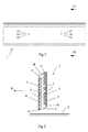
- a wearing element also referred to as wearing cutting element or cutting edge, is illustrated, designed to be mounted to the lower part of a plow blade 12 by suitable securing means (not shown).
- the plow blade 12 is attached to any suitable vehicle 13 such as a lorry, truck, tractor or the like.
- the cutting side (front side) of the wearing element is the side facing the direction of travel D, when the vehicle 13 fitted with the plow blade 12 drives in the forward direction.
- Fig. 2 illustrates the front side of the wearing element 1, and compressing means 7 also being standardized fastening means, are located on the element 1 in a standardized mutual relationship, as further elucidated below.
- Fig. 3 illustrates a front plate 3 on the cutting side of the wearing element 1, and the lower part 8 of the front plate 3 interacts with a road, runway or any ground surface G that should be cleared from, for example, snow, slush, ice, mud, soil, stones or debris.
- the forward direction of travel is indicated by the arrow D.
- the elastomeric element 4 is permanently bonded to the plates 2, 3, typically by vulcanization, and provides a resilient relationship between the plates 2, 3.
- the plates 2, 3 and the elastomeric element 4 are rectangular in shape when seen from the direction of travel D. It should be noted that the level of resilience may be varied, but preferably the elastomeric element 4 provides rather firm damping between the plates 2, 3 in order to efficiently absorb shock and impacts.
- the side of the mounting plate 2 opposite the elastomer element 4 is preferably covered with a resilient layer 5, and the side of the front plate 3 opposite the elastomeric element 4 is preferably covered with a similar resilient layer 6.
- the wearing element 1 has parallelogram-shaped cross-section (see Fig. 3) with two parallel outer surfaces and two inclined edge surfaces one of which is positioned near the ground surface G in operation.
- the plates 5, 6 are offset in a direction of height of the wearing element 1, as is clearly illustrated in Fig. 3.
- the lower part 9 of the elastomeric element 4 is preferably upwardly slanted as seen from the front plate 3, and as illustrated in Fig. 3, but the lower part 9 may have any suitable profile, such as a concave, convex or straight profile.
- the wearing element 1 is turnable and has a symmetrical shape, and compressing/mounting means 7 are symmetrically arranged on both the front plate 3 and the mounting plate 2, respectively.
- a user dismounts the wearing element 1, flips it, and mounts it with the front plate 3 in the direction of the plow blade.
- the mounting plate 2 is facing the direction of travel D and provides the same functionality as the front plate 3 did when the front plate 3 was facing the direction D of travel.
- the upper part 11 of the mounting plate 2 has the former position of the lower part 8 of the front plate 3, as seen in a relationship to plow blade and ground surface G.
- the front plate 3 is preferably similar to the mounting plate, and may advantageously be identical.
- the word "similar” reflects the fact that the plates 2, 3 may be of different thicknesses or heights, while still providing the turnable functionality described above.
- the wearing element 1 may have the elastomeric element 4 made of polyurethane, rubber, any other polymer material or a combination thereof, and preferably, the resilient layers 5, 6 also are made of any of these materials.
- the wearing element 1 may have the mounting plate 2 and the front plate 3 made of ceramics, metallic material such as steel, polymeric material or any other hard material, or a combination thereof.
- the mounting plate 2 and the front plate 3 may advantageously be made of a material less wear-resistant than the material of the elastomeric element 4. This feature results in a hydroplaning effect between the elastomeric element 4 and the roadway G when snow, slush and ice are removed, which decreases friction and hence wear on the wearing element 1.
- the compressing means 7 preferably comprise through holes in the wearing element 1, machine screws (not shown) inserted in the respective holes and nuts (not shown) screwed onto the screws and tightened for compressing the plates 2, 3, but any technique for moving the plates 2, 3 closer to each other may be used.
- the diameter of the screws is preferably smaller than the diameter of the through holes in order avoid interference of the resilient relationship between the plates 2, 3.
- the compressing means are also mounting means for attaching the wearing element 1 to the plow blade 12, and in this case, when the wearing element 1 is mounted, the machine screws also pass through holes (not shown) arranged in the blade 12.
- One set of compressing/mounting means 7 per wearing element 1 is sufficient, but for optimum result a plurality of sets should be provided.
- the through holes in the wearing element 1 are preferably also arranged with a diameter and a mutual relationship according to plow blade standards, in consideration of a slightly greater diameter of the wearing element through holes.
- the mounting means 7 of the wearing element 1 are arranged in the center of the wearing element 1, or at least close to the center of the wearing element 1. This provides further damping when the lower part 8 of the front plate 3 is subjected to impacts from the ground surface G along the direction of driving D. Since the lower parts 8, 10 of the plates 3, 2, are brought closer by the impact, the elastomeric element 4 is compressed at its lower part 9. When the lower part 9 of the elastomeric element 4 is compressed, the part 9 bulges towards the ground surface G, thereby lifting the wearing element 1 from the ground G, which provides better damping and reduces friction between the ground G and the wearing element 1. Due to constant volume characteristics of the elastomeric element 4, its lower part 9 regains its original shape after absorption of the impact.
- the upper (opposite the lower) parts of the plates 3, 2 may be spaced further apart as the upper part of the elastomeric element 4 is extended.
- the lower part 9 of the elastomeric element 4 may be compressed without the upper (opposite the lower) part of the elastomeric element 4 being extended.
- the mounting means 7 of the wearing element 1 must not comprise through holes, but may also be any means for attaching the wearing element 1 to the plow blade 12.
- the lower and/or the upper parts of the plates 2, 3 may also be serrated, jagged or toothed in order to provide a serrated ground surface G during operation.
Landscapes
- Engineering & Computer Science (AREA)
- Architecture (AREA)
- Civil Engineering (AREA)
- Structural Engineering (AREA)
- Cleaning Of Streets, Tracks, Or Beaches (AREA)
Priority Applications (1)
| Application Number | Priority Date | Filing Date | Title |
|---|---|---|---|
| EP05110266A EP1783280A1 (de) | 2005-11-02 | 2005-11-02 | Verschleißleiste für den Räumschild eines Schneepfluges |
Applications Claiming Priority (1)
| Application Number | Priority Date | Filing Date | Title |
|---|---|---|---|
| EP05110266A EP1783280A1 (de) | 2005-11-02 | 2005-11-02 | Verschleißleiste für den Räumschild eines Schneepfluges |
Publications (1)
| Publication Number | Publication Date |
|---|---|
| EP1783280A1 true EP1783280A1 (de) | 2007-05-09 |
Family
ID=36095898
Family Applications (1)
| Application Number | Title | Priority Date | Filing Date |
|---|---|---|---|
| EP05110266A Withdrawn EP1783280A1 (de) | 2005-11-02 | 2005-11-02 | Verschleißleiste für den Räumschild eines Schneepfluges |
Country Status (1)
| Country | Link |
|---|---|
| EP (1) | EP1783280A1 (de) |
Citations (5)
| Publication number | Priority date | Publication date | Assignee | Title |
|---|---|---|---|---|
| DE7702414U1 (de) * | 1977-01-28 | 1977-05-12 | Gummi Kueper Kg, 4630 Bochum | Räumleiste für einen Schneepflug |
| US4347677A (en) * | 1979-02-05 | 1982-09-07 | Gummi Kuper Gmbh & Co. Kg | Snow removal bar for the snow removal plate of a snow plow |
| DE3239518C1 (de) * | 1982-10-26 | 1984-04-05 | Hopp, Hans-Jochen, 5800 Hagen | Räumleiste für Schneepflüge |
| DE8707182U1 (de) * | 1987-05-19 | 1987-08-06 | Gummi-Küper GmbH & Co KG, 4630 Bochum | Auswechselbare Schneeräumleiste |
| US5743032A (en) * | 1993-01-22 | 1998-04-28 | Vauhkonen; Pertti | Plough blade arrangement |
-
2005
- 2005-11-02 EP EP05110266A patent/EP1783280A1/de not_active Withdrawn
Patent Citations (5)
| Publication number | Priority date | Publication date | Assignee | Title |
|---|---|---|---|---|
| DE7702414U1 (de) * | 1977-01-28 | 1977-05-12 | Gummi Kueper Kg, 4630 Bochum | Räumleiste für einen Schneepflug |
| US4347677A (en) * | 1979-02-05 | 1982-09-07 | Gummi Kuper Gmbh & Co. Kg | Snow removal bar for the snow removal plate of a snow plow |
| DE3239518C1 (de) * | 1982-10-26 | 1984-04-05 | Hopp, Hans-Jochen, 5800 Hagen | Räumleiste für Schneepflüge |
| DE8707182U1 (de) * | 1987-05-19 | 1987-08-06 | Gummi-Küper GmbH & Co KG, 4630 Bochum | Auswechselbare Schneeräumleiste |
| US5743032A (en) * | 1993-01-22 | 1998-04-28 | Vauhkonen; Pertti | Plough blade arrangement |
Similar Documents
| Publication | Publication Date | Title |
|---|---|---|
| CA2965426C (en) | Adjustable sweeping blade device and sweeping blade assembly | |
| US5743032A (en) | Plough blade arrangement | |
| US10865534B2 (en) | Snowplow with ground contour following cutting edge and impact absorption | |
| CA2975113A1 (en) | Elastomeric plow edge | |
| US20130174452A1 (en) | Plow Blade Assembly | |
| EP3408454B1 (de) | Kehrschaufelvorrichtung mit verstellbaren schaufeln | |
| US10113282B2 (en) | Cutting edge attachment for snow plow | |
| US20240426068A1 (en) | Plow guard | |
| CA2995291C (en) | Snow plow blade | |
| EP1783280A1 (de) | Verschleißleiste für den Räumschild eines Schneepfluges | |
| EP3940145B1 (de) | Kehrschaufelvorrichtung und kehrschaufelanordnung für ein fahrzeug | |
| CN105696513B (zh) | 一种适用于被车辆压实的雪后路面松雪铲 | |
| CA3113187C (en) | Sweeping blade and sweeping blade assembly for a vehicle | |
| US11795641B2 (en) | Sweeping blade and sweeping blade assembly for a vehicle | |
| RU2316627C2 (ru) | Держатель ножа для снегоуборочного устройства | |
| CA2784493C (en) | Elastomeric plow edge |
Legal Events
| Date | Code | Title | Description |
|---|---|---|---|
| PUAI | Public reference made under article 153(3) epc to a published international application that has entered the european phase |
Free format text: ORIGINAL CODE: 0009012 |
|
| AK | Designated contracting states |
Kind code of ref document: A1 Designated state(s): AT BE BG CH CY CZ DE DK EE ES FI FR GB GR HU IE IS IT LI LT LU LV MC NL PL PT RO SE SI SK TR |
|
| AX | Request for extension of the european patent |
Extension state: AL BA HR MK YU |
|
| AKX | Designation fees paid | ||
| REG | Reference to a national code |
Ref country code: DE Ref legal event code: 8566 |
|
| STAA | Information on the status of an ep patent application or granted ep patent |
Free format text: STATUS: THE APPLICATION IS DEEMED TO BE WITHDRAWN |
|
| 18D | Application deemed to be withdrawn |
Effective date: 20071110 |