EP1783301B1 - Stützvorrichtung für ein Gerät zum Heben und Manipulieren von Platten oder Paneelen - Google Patents
Stützvorrichtung für ein Gerät zum Heben und Manipulieren von Platten oder Paneelen Download PDFInfo
- Publication number
- EP1783301B1 EP1783301B1 EP06301056A EP06301056A EP1783301B1 EP 1783301 B1 EP1783301 B1 EP 1783301B1 EP 06301056 A EP06301056 A EP 06301056A EP 06301056 A EP06301056 A EP 06301056A EP 1783301 B1 EP1783301 B1 EP 1783301B1
- Authority
- EP
- European Patent Office
- Prior art keywords
- support
- pin
- support base
- pawl
- head
- Prior art date
- Legal status (The legal status is an assumption and is not a legal conclusion. Google has not performed a legal analysis and makes no representation as to the accuracy of the status listed.)
- Not-in-force
Links
- 238000009826 distribution Methods 0.000 claims abstract description 4
- NJPPVKZQTLUDBO-UHFFFAOYSA-N novaluron Chemical compound C1=C(Cl)C(OC(F)(F)C(OC(F)(F)F)F)=CC=C1NC(=O)NC(=O)C1=C(F)C=CC=C1F NJPPVKZQTLUDBO-UHFFFAOYSA-N 0.000 abstract 2
- 230000000295 complement effect Effects 0.000 description 5
- 238000004519 manufacturing process Methods 0.000 description 4
- 238000003466 welding Methods 0.000 description 4
- 238000009434 installation Methods 0.000 description 3
- 230000006978 adaptation Effects 0.000 description 2
- 239000000463 material Substances 0.000 description 2
- 238000005457 optimization Methods 0.000 description 2
- 241000897276 Termes Species 0.000 description 1
- 240000008042 Zea mays Species 0.000 description 1
- 239000000470 constituent Substances 0.000 description 1
- 230000009193 crawling Effects 0.000 description 1
- 230000001419 dependent effect Effects 0.000 description 1
- 238000011065 in-situ storage Methods 0.000 description 1
- 238000005192 partition Methods 0.000 description 1
- 230000000284 resting effect Effects 0.000 description 1
- 238000005096 rolling process Methods 0.000 description 1
Images


Classifications
-
- E—FIXED CONSTRUCTIONS
- E04—BUILDING
- E04F—FINISHING WORK ON BUILDINGS, e.g. STAIRS, FLOORS
- E04F21/00—Implements for finishing work on buildings
- E04F21/18—Implements for finishing work on buildings for setting wall or ceiling slabs or plates
- E04F21/1805—Ceiling panel lifting devices
- E04F21/1822—Ceiling panel lifting devices with pivotally mounted arms
Definitions
- the invention relates to the technical sector of lifting and handling devices used in the building for the presentation of plates of any material to form false ceilings or development under crawling and partitions.
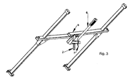
- FIG. 1 to 3 there is described a device for articulating the support of plates or panels, articulated with respect to a fixed section (1) horizontal secured to the upper end of the mast (2) of the device.
- This device comprises a support base (3) having a flat top wall of large width with a U-shaped stirrup (4) serving as a support position and fixing to the frame (5) of the panel door and / or plate holder .
- An operating arm (6) is secured to the support base and controls the articulation and positioning of the device relative to the mast.
- Locking means with operating handle (7) and lock bolt (8) lock in position and release the tilting of the support base.
- the support base has an opening (3a) for passage of a finger (9) for positioning and stopping the plate or panel in the stop position.
- the locking device for bolt according to a conventional configuration of lock, is to be mounted and generates additional costs and interventions and manipulations.
- the applicant has also been interested in the optimization and manufacture of the hoisting and handling equipment by offering other functions that meet a need for on-site handling of equipment. Indeed, it has been found that the loading of the support frame of the plates on the orientation device of the plates and panels was done in a rather empirical way. Indeed, the support frame of the plates is threaded and guided on the U shaped profiled stirrup disposed on the upper face of the articulating support base. To do this, it is common that the operator, to set up the panel plate support frame, put the operating lever of the device in support on his shoulder to view the establishment of it. This support is therefore inclined, the operator then has both hands free to ensure positioning. This approach and manipulation is therefore impractical.
- the support device for lifting apparatus and handling of plates or panels comprising a mast and a support frame carries plates or panel doors, comprises a support base and a support base articulated on said support base, said base support being intended to be disposed at the end of said mast, the support frame being positioned on said support base in the mounted position, the device being characterized in that said support base is a U-shaped section receiving, between its wings, a first axis ensuring the articulation of said support base and a second axis on which is freely pivotally disposed a locking pawl swinging in the locking position by its mass distribution, said pawl having a hook head intended to cooperate and adjust around a third axis forming a finger disposed overflow from the support base, a right rear face intended to form a stop end for the support frame when the pawl is locked and a lever arm and maneuver having, at the end, an unbalanced form.
- the lifting and handling apparatus for plates or panels intended to be laid in ceilings or against the walls is referenced as a whole by (A) and is arranged in any appropriate way at its base with rolling means (R ), gripping means (B) and cable control for putting in position telescopic or not the constituent elements of the mast (2).
- the mast receives the device (D) of the invention to which is applied and fixed, either removably or fixedly by welding, the support frame (5) door plates or door panels.
- the mast may also allow the attachment of the receptacle (P) for the positioning of power tools or other equipment necessary for the operator.
- the device plate or door panels applies to any design of lifting and handling devices for this purpose and the representation of the figure 4 is given to facilitate the understanding of it.
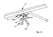
- the device (D) plate support has been designed and arranged to meet different functions that will be discussed below. More particularly, the device comprises, from the end of the mast, a U-shaped support base (10) secured to the mast by its bottom (10a), by welding or otherwise, and is horizontal with its free face oriented. to the top. Between its parallel and vertical lateral wings (10b-10c), two hinge pins (11-12) are arranged, one (11) disposed rearwardly and the other (12) in the front part of the base.
- the axis (11) allows, in a conventional manner, the articulation of the support base (13) on which is positioned directly or indirectly the support frame (5) plate holder or panel door.
- the support base is arranged on its upper face with a stirrup shape (4) forming a slide insert and fixed in any appropriate manner and delimiting a slot (4a) and sliding of the support base (5) whose lower profile is arranged in a complementary manner.
- the stirrup can receive the base of the support (5) in two different positions of 90 °, one allowing the installation so-called horizontal under ceiling and the other the so-called inclined creeping installation.
- the support base receives the support frame which is permanently fixed by welding or equivalent.
- the support base (13) is, according to the invention, made in the form of a U-shaped profile with wings (13a-13b) mounted on the axis (11) and inserted into the interior volume between the wings ( 10b - 10c) of the support base (10). Said base also receives a fixed axis (14) projecting from one side, mounted between said wings (13a - 13b), the projecting portion (14a) acting as a finger.
- An L-shaped operating handle (15) is fixed at one end (15a) to said support base by welding or the like, while the gripping portion (15b) is in a plane perpendicular to and facing the operator.
- the support base (10) receives, in its front part, an axis (12) on which is freely articulated a pawl (16) having a very particular profile.
- This ratchet is first mounted on the axis (12) with a slight eccentricity creating an imbalance, so that it is animated by a rocking movement.
- Said pawl has, on the inner side of the support base (10), a hook-shaped head (16a) disposed inwardly facing its other end (16c).
- the rear face (16d) of the head is straight and is located in a plane perpendicular to the horizontal bottom of the support base and the horizontal bottom face of the support base when it is in a lowered position.
- the head (16a) of the pawl is sufficiently high to protrude from the horizontal plane of the support base when the pawl is hooked on the finger (14a) to constitute a bearing abutment face to the support frame of the panels or free-standing plates, regardless of the orientation of the support base (5) in the passage slot (4a) of the stirrup (4).
- the head (16a) has, beyond its rear face, a curvilinear profiled upper portion (16e) constituting a bearing face in the circumstances which will be specified thereafter.
- the pawl has an opening (16f) for engagement on the shaft (12).
- This ratchet has, at its other end, beyond the hinge axis, a form of operating lever with an unbalance or ballast profile (16g) resulting, in case of non-solicitation, the tilting of the ratchet forward because of its mass distribution by counteracting weight.
- the bottom face of the support base has an opening or clearance (10d) allowing the articulation of the lever and its tilting and its passage through said bottom face.
- the loading of plates or panels on the support frame can be carried out safely, either after tilting of the support base to the horizontal and locking in position, or by the support of the finger (14a) on the profiled head of the pawl.
- the pawl is tilted backwards to allow the hooking of the finger (14a).
- the pawl returns to the locking position by unbalance.
- the installation of the panels or plates is performed very easily and quickly by a double action of the operator on the one hand unlocking the pawl by its lifting by its gripping portion, then by the orientation of the associated maneuvering arm at the base support.
- the orientation of the device makes it possible to present the plate or panels to be positioned safely. There is no longer need for the operator to position, as it did previously, the operating arm resting on the shoulder to ensure the establishment of the support frame plate or panels.
- the pawl ensures, by its different positions, the locking functions of the support base, non-return stop of the plate support frame, support, if necessary, in an inclined position of the support base on the upper part. the ratchet by having a seat or allow oblique loading.
Landscapes
- Engineering & Computer Science (AREA)
- Architecture (AREA)
- Civil Engineering (AREA)
- Structural Engineering (AREA)
- Conveying And Assembling Of Building Elements In Situ (AREA)
- Load-Engaging Elements For Cranes (AREA)
- Forklifts And Lifting Vehicles (AREA)
- Supports Or Holders For Household Use (AREA)
- Elevator Door Apparatuses (AREA)
- Hinges (AREA)
- Window Of Vehicle (AREA)
Claims (7)
- Auflagevorrichtung (D) für ein Hebe- und Fördergerät (A) von Platten mit einem Mast (2) und einem Plattentragegerüst (5), wobei diese Vorrichtung (D) einen Tragesockel (10) und eine an diesem Tragesockel (10) angelenkte Auflagebasis (13) umfasst, wobei der Tragesockel (10) zur Befestigung am Ende des besagten Mastes (2) bestimmt ist, während das Tragegerüst (5) in montierter Stellung auf der besagten Auflagebasis (13) positioniert ist, dadurch gekennzeichnet, dass der Tragesockel (10) ein U-förmiges Profil aufweist, das zwischen den Flügelstücken (11) eine erste Achse (11) für die gelenkige Lagerung der Auflagebasis (13) und eine zweite Achse (12) aufnimmt, an der eine freie schwenkbare Sperrklinke (16) angeordnet ist, die durch ihre Masseverteilung auf die Verriegelungsposition kippt, wobei diese Klinke einen hakenförmigen (16b) Kopfteil (16a) besitzt, der dazu bestimmt ist, sich im Zusammenwirken um eine dritte Achse (14) herum einzupassen, die einen aus der Auflagebasis (13) vorspringenden Stift (14a) bildet, und außerdem eine gerade Rückseite (16d) am Kopfteil, die bei verriegelter Klinke einen Anschlag für das Tragegerüst (5) bilden soll, sowie einen Hebel- und Betätigungsarm, der am Ende als Unwucht ausgebildet ist (16g), aufweist.
- Vorrichtung nach Anspruch 1, dadurch gekennzeichnet, dass der besagte Tragesockel (10) dazu bestimmt ist, an seinem Bodenteil (10a) fest mit dem Mast verbunden zu werden, und sich in Gebrauchsstellung mit seiner nach oben gerichtete freien Fläche in horizontaler Lage befindet, wobei die beiden Gelenkachsen (11, 12) zwischen den parallel und senkrecht am Tragesockel (10) verlaufenden Seitenflügeln (10b, 10c) angeordnet sind, wobei sich die erste Achse (11) hinten und die zweite Achse (12) im vorderen Teil des Sockels befindet und die besagte Auflagebasis (13) als U-förmiges Profil mit Flügelteilen (13a, 13b), die auf der ersten Achse (11) angebracht und in das Innenvolumen zwischen den beiden Seitenflügeln (10b, 10c) des Tragesockels (10) eingepasst werden, ausgebildet ist, wobei die Auflagebasis (13) die dritte ortsfeste Achse aufnimmt (14), die auf einer Seite vorsteht und zwischen den besagten Seitenflügeln (13a, 13b) der Auflagebasis (13) angebracht ist, wobei der vorspringende Teil (14a) der dritten Achse (14) als Stift dient.
- Vorrichtung nach einem der Ansprüche 1 und 2, dadurch gekennzeichnet, dass sie einen L-förmig profilierten Handgriff (15) umfasst, der an einem Ende (15a) an der besagten Auflagebasis (13) befestigt ist, während sich der Griffteil (15b) senkrecht dazu und dem Bediener zugewandt befindet.
- Vorrichtung nach Anspruch 1, dadurch gekennzeichnet, dass der Tragesockel (10) an seinem vorderen Teil die besagte zweite Achse aufnimmt (12), an der die Klinke (16) mit einer ein Ungleichgewicht schaffenden Mittelpunktsverschiebung angelenkt ist, so dass eine Kippbewegung entsteht, wobei die besagte Klinke innen im Tragesockel (10) einen Kopf (16a) in Form eines Hakens (16b) aufweist, der innen dem anderen Klinkenende (16c) zugewandt ist, und die Rückseite (16d) des Kopfstücks gerade und in einer senkrechten Ebene zu dem waagrechten Boden des Tragesockels (10) und zur waagrechten Bodenfläche der Auflagebasis (13) angeordnet ist, wobei der Kopf (16a) der Klinke hoch genug ist, um aus der waagrechten Ebene der Auflagebasis (13) vorzuragen, wenn die Klinke am Stift (14a) der dritten Achse (14) eingehakt wird, um eine Anschlagfläche für das Tragegerüst (5) zu bilden.
- Vorrichtung nach Anspruch 4, dadurch gekennzeichnet, dass der Kopf (16a) über seine Rückseite hinaus einen kurvenförmig profilierten oberen Teil (16e) aufweist, der eine Auflagefläche bildet.
- Vorrichtung nach Anspruch 4, dadurch gekennzeichnet, dass die Klinke eine Öffnung (16f) zum Einführen auf die besagte zweite Achse (12) aufweist.
- Vorrichtung nach Anspruch 2, dadurch gekennzeichnet, dass die Bodenfläche des Tragesockels (10) eine Öffnung bzw. Aussparung (10d) für die gelenkige Lagerung des Hebels und sein Kippen durch die besagte Bodenfläche hindurch aufweist.
Applications Claiming Priority (1)
| Application Number | Priority Date | Filing Date | Title |
|---|---|---|---|
| FR0553341A FR2893056B1 (fr) | 2005-11-04 | 2005-11-04 | Dispositif support de porte plaques de materiau pour appareil de levage et de manutention |
Publications (2)
| Publication Number | Publication Date |
|---|---|
| EP1783301A1 EP1783301A1 (de) | 2007-05-09 |
| EP1783301B1 true EP1783301B1 (de) | 2010-07-14 |
Family
ID=36677178
Family Applications (1)
| Application Number | Title | Priority Date | Filing Date |
|---|---|---|---|
| EP06301056A Not-in-force EP1783301B1 (de) | 2005-11-04 | 2006-10-17 | Stützvorrichtung für ein Gerät zum Heben und Manipulieren von Platten oder Paneelen |
Country Status (10)
| Country | Link |
|---|---|
| US (1) | US20070104558A1 (de) |
| EP (1) | EP1783301B1 (de) |
| AT (1) | ATE474110T1 (de) |
| DE (1) | DE602006015411D1 (de) |
| DK (1) | DK1783301T3 (de) |
| ES (1) | ES2347935T3 (de) |
| FR (1) | FR2893056B1 (de) |
| NO (1) | NO20064938L (de) |
| RU (1) | RU2412316C2 (de) |
| UA (1) | UA90472C2 (de) |
Families Citing this family (10)
| Publication number | Priority date | Publication date | Assignee | Title |
|---|---|---|---|---|
| FR2946376B1 (fr) * | 2009-06-04 | 2015-05-29 | Roger Modelin Sas | Dispositif de verrouillage d'une rallonge integree au support porte-plaques de materiau pour appareils de levage et de manutention |
| FR2967180B1 (fr) * | 2010-11-10 | 2012-11-02 | Zhuhai Quan Da Industry & Commerce | Appareil leve-plaques pour la pose de plaques dans le domaine du batiment |
| RU2509850C1 (ru) * | 2013-03-06 | 2014-03-20 | Александр Иванович Худолий | Устройство для установки листа на потолок |
| US9321615B2 (en) | 2013-04-02 | 2016-04-26 | Snap-On Incorporated | Panel hoist |
| FR3028279B1 (fr) * | 2014-11-06 | 2017-03-31 | Grehal Pierre Ets Cie Sa | Mecanisme de fixation pivotante d’un porte-plaque sur un mat telescopique d’un appareil de levage de plaques, et appareil de levage de plaque muni d’un tel mecanisme |
| US9758974B1 (en) * | 2016-06-09 | 2017-09-12 | Dewell Reeves | Sheetrock lifting device |
| FR3061919B1 (fr) * | 2017-01-18 | 2019-11-22 | Mob Mondelin Sas | Dispositif porte plaque de materiau pour appareil de levage et de manutention permettant la pose de plaque a l'horizontale, sous rampant et a la verticale |
| US10240354B2 (en) * | 2017-07-28 | 2019-03-26 | Alfredo RODRIGUES | Drywall lifting apparatus |
| USD974692S1 (en) | 2020-08-10 | 2023-01-03 | John D. Cullinan | Vehicle hardtop lift |
| US12448258B1 (en) | 2020-10-28 | 2025-10-21 | John D. Cullinan | Apparatus and method for removal of vehicle hardtop |
Family Cites Families (15)
| Publication number | Priority date | Publication date | Assignee | Title |
|---|---|---|---|---|
| SU94280A1 (ru) * | 1951-01-09 | 1951-11-30 | В.Г. Измайлов | Подъемное устройство, преимущественно дл подвода к потолку листов сухой штукатурки |
| US3040922A (en) * | 1958-09-30 | 1962-06-26 | Kappen John William | Articulated arm structure |
| US3083948A (en) * | 1962-01-15 | 1963-04-02 | Goldfader Sol | Electro-lift |
| US3425365A (en) * | 1966-09-13 | 1969-02-04 | Thoreson Mccosh Inc | Tilt table |
| US6234501B1 (en) * | 1970-02-23 | 2001-05-22 | Chih-Liang Chen | Foldable scooter with head tube assembly, brake and suspension |
| FR2552478B2 (fr) * | 1983-09-28 | 1985-11-08 | Chatellerault Armes Cycles | Appareil pour elever et poser les plaques au plafond |
| US5322403A (en) * | 1992-03-11 | 1994-06-21 | Herde Robert A | Versatile, movable panel and utility support lift |
| FR2741901B1 (fr) * | 1995-12-01 | 1998-02-27 | Tradition De L Outil A Main T | Appareil pour la mise en place de plaques de plafond |
| FR2758150B1 (fr) * | 1997-01-03 | 1999-03-12 | Roger Mondelin Sa | Dispositif de securite applique aux appareils de levage de materiaux au niveau des plafonds |
| US5893283A (en) * | 1997-05-07 | 1999-04-13 | Mas-Hamilton Group | Solenoid controlled bolt control for an electronic lock |
| US6164611A (en) * | 1997-09-18 | 2000-12-26 | Gamber Johnson | Quad-motion device |
| FR2780428B1 (fr) * | 1998-06-30 | 2000-08-25 | Roger Mondelin Sa | Appareil de levage et de manutention de plaques de materiau destinees notamment a la couverture de plafond |
| US6192808B1 (en) * | 1999-05-20 | 2001-02-27 | Sico Incorporated | Folding table with latching linkage |
| US6244810B1 (en) * | 2000-02-18 | 2001-06-12 | Guadalupe Reyes | Drywall handyman |
| FR2862682B1 (fr) * | 2003-11-26 | 2006-03-31 | Roger Mondelin Sa | Dispositif d'orientation de porte-plaques de materiau pour appareil de levage et de manutention |
-
2005
- 2005-11-04 FR FR0553341A patent/FR2893056B1/fr not_active Expired - Fee Related
-
2006
- 2006-10-17 DK DK06301056.5T patent/DK1783301T3/da active
- 2006-10-17 ES ES06301056T patent/ES2347935T3/es active Active
- 2006-10-17 DE DE602006015411T patent/DE602006015411D1/de active Active
- 2006-10-17 AT AT06301056T patent/ATE474110T1/de not_active IP Right Cessation
- 2006-10-17 EP EP06301056A patent/EP1783301B1/de not_active Not-in-force
- 2006-10-26 US US11/553,359 patent/US20070104558A1/en not_active Abandoned
- 2006-10-27 NO NO20064938A patent/NO20064938L/no not_active Application Discontinuation
- 2006-11-03 UA UAA200611608A patent/UA90472C2/ru unknown
- 2006-11-03 RU RU2006139013/03A patent/RU2412316C2/ru not_active IP Right Cessation
Also Published As
| Publication number | Publication date |
|---|---|
| US20070104558A1 (en) | 2007-05-10 |
| FR2893056B1 (fr) | 2009-11-13 |
| ATE474110T1 (de) | 2010-07-15 |
| UA90472C2 (ru) | 2010-05-11 |
| DE602006015411D1 (de) | 2010-08-26 |
| ES2347935T3 (es) | 2010-11-25 |
| DK1783301T3 (da) | 2010-11-08 |
| RU2412316C2 (ru) | 2011-02-20 |
| FR2893056A1 (fr) | 2007-05-11 |
| EP1783301A1 (de) | 2007-05-09 |
| RU2006139013A (ru) | 2008-05-10 |
| NO20064938L (no) | 2007-05-07 |
Similar Documents
| Publication | Publication Date | Title |
|---|---|---|
| EP1783301B1 (de) | Stützvorrichtung für ein Gerät zum Heben und Manipulieren von Platten oder Paneelen | |
| EP1927707B1 (de) | Sicherheitsvorrichtung an Maschinen zum Heben von Wand- und Deckenplatten | |
| EP1640531B1 (de) | Hebe- und Fördergerät mit Vorrichtung zum Ausrichten einer Materialtragschale | |
| EP0737782A1 (de) | Beidseitige bedienbare Verriegelungsvorrichtung für eine Schachtabdeckung | |
| CA1297135C (fr) | Ferrure de verrouillage notamment pour ouvrant coulissant | |
| FR2540168A1 (fr) | Appareils montes sur colonne | |
| EP1911906A1 (de) | Haltevorrichtung zur bündigen Verlegung von Gipskartonplatten unterschiedlicher Breite mit Hebe- und Transportgeräten für diese Platten | |
| EP1536084B1 (de) | Vorrichtung zum Ausrichten eines Plattenträgers für ein Hebe- und Haltegerät | |
| EP2003271A1 (de) | Notwerkzeug, wie beispielsweise eine Axt, das zum Auslösen einer Sicherungsvorrichtung geeignet ist, die den Notzugang zu einer öffentlichen Infrastruktureinrichtung sichert | |
| FR2529937A1 (fr) | Dispositif de fermeture a pene profile enveloppant rotatif et a gache rentrante | |
| EP1698513A1 (de) | Wechselbehälter mit eingebautem Leiter zur Aufnahme und zum Transport von Materialien | |
| EP1098049A1 (de) | Revisionsschacht mit verstärkter Dichtung für ein Wand- oder Bodenteil | |
| FR2817902A1 (fr) | Dispositif de condamnation securisee de l'acces a une echelle a crinoline | |
| EP1110649B1 (de) | Apparatus for cutting workpieces such as tiles | |
| EP0754920B1 (de) | Vorrichtung zum Öffnen oder Schliessen einer Tür für einen Raum und Backofen mit einer solchen Vorrichtung | |
| EP3351704B1 (de) | Halterungsvorrichtung für werkstoffplatte für ein hub- und fördergerät, das eine plattenverlegung sowohl horizontal, unter schrägen und auch vertikal ermöglicht | |
| EP0269473A1 (de) | Verriegelung eines Riegels in der verriegelten Stellung | |
| FR2672115A3 (fr) | Poignee interne de commande d'une porte coulissante pour chambres frigorifiques. | |
| EP1908901B1 (de) | Griff zum Öffnen und Schließen von Öffnungsflügeln | |
| FR2711175A1 (fr) | Dispositif d'ouverture-fermeture de portes de garages et similaires avec opérateur de fonctionnement. | |
| FR2493896A1 (fr) | Serrure de porte a sens de montage indifferent | |
| EP3512742A1 (de) | Vorrichtung zur befestigung einer leiter an einem fahrzeugdachträger oder dergleichen | |
| EP1149973B1 (de) | Verschlussvorrichtung für eine zweiflügelige Tür | |
| FR3106150A3 (fr) | Chariot de support pour panneaux coulissants | |
| FR2757366A1 (fr) | Trappe a volet pivotant et amovible utilisee notamment dans les habillages de baignoires et pour la visite d'autres elements encastres |
Legal Events
| Date | Code | Title | Description |
|---|---|---|---|
| PUAI | Public reference made under article 153(3) epc to a published international application that has entered the european phase |
Free format text: ORIGINAL CODE: 0009012 |
|
| AK | Designated contracting states |
Kind code of ref document: A1 Designated state(s): AT BE BG CH CY CZ DE DK EE ES FI FR GB GR HU IE IS IT LI LT LU LV MC NL PL PT RO SE SI SK TR |
|
| AX | Request for extension of the european patent |
Extension state: AL BA HR MK YU |
|
| 17P | Request for examination filed |
Effective date: 20070618 |
|
| 17Q | First examination report despatched |
Effective date: 20070725 |
|
| RAP1 | Party data changed (applicant data changed or rights of an application transferred) |
Owner name: ROGER MONDELIN SAS |
|
| AKX | Designation fees paid |
Designated state(s): AT BE BG CH CY CZ DE DK EE ES FI FR GB GR HU IE IS IT LI LT LU LV MC NL PL PT RO SE SI SK TR |
|
| GRAP | Despatch of communication of intention to grant a patent |
Free format text: ORIGINAL CODE: EPIDOSNIGR1 |
|
| GRAS | Grant fee paid |
Free format text: ORIGINAL CODE: EPIDOSNIGR3 |
|
| GRAA | (expected) grant |
Free format text: ORIGINAL CODE: 0009210 |
|
| AK | Designated contracting states |
Kind code of ref document: B1 Designated state(s): AT BE BG CH CY CZ DE DK EE ES FI FR GB GR HU IE IS IT LI LT LU LV MC NL PL PT RO SE SI SK TR |
|
| REG | Reference to a national code |
Ref country code: GB Ref legal event code: FG4D Free format text: NOT ENGLISH |
|
| REG | Reference to a national code |
Ref country code: CH Ref legal event code: EP |
|
| REG | Reference to a national code |
Ref country code: IE Ref legal event code: FG4D |
|
| REF | Corresponds to: |
Ref document number: 602006015411 Country of ref document: DE Date of ref document: 20100826 Kind code of ref document: P |
|
| REG | Reference to a national code |
Ref country code: NL Ref legal event code: T3 |
|
| REG | Reference to a national code |
Ref country code: DK Ref legal event code: T3 |
|
| LTIE | Lt: invalidation of european patent or patent extension |
Effective date: 20100714 |
|
| PG25 | Lapsed in a contracting state [announced via postgrant information from national office to epo] |
Ref country code: LT Free format text: LAPSE BECAUSE OF FAILURE TO SUBMIT A TRANSLATION OF THE DESCRIPTION OR TO PAY THE FEE WITHIN THE PRESCRIBED TIME-LIMIT Effective date: 20100714 Ref country code: FI Free format text: LAPSE BECAUSE OF FAILURE TO SUBMIT A TRANSLATION OF THE DESCRIPTION OR TO PAY THE FEE WITHIN THE PRESCRIBED TIME-LIMIT Effective date: 20100714 Ref country code: AT Free format text: LAPSE BECAUSE OF FAILURE TO SUBMIT A TRANSLATION OF THE DESCRIPTION OR TO PAY THE FEE WITHIN THE PRESCRIBED TIME-LIMIT Effective date: 20100714 |
|
| REG | Reference to a national code |
Ref country code: IE Ref legal event code: FD4D |
|
| PG25 | Lapsed in a contracting state [announced via postgrant information from national office to epo] |
Ref country code: CY Free format text: LAPSE BECAUSE OF FAILURE TO SUBMIT A TRANSLATION OF THE DESCRIPTION OR TO PAY THE FEE WITHIN THE PRESCRIBED TIME-LIMIT Effective date: 20100714 Ref country code: PL Free format text: LAPSE BECAUSE OF FAILURE TO SUBMIT A TRANSLATION OF THE DESCRIPTION OR TO PAY THE FEE WITHIN THE PRESCRIBED TIME-LIMIT Effective date: 20100714 Ref country code: PT Free format text: LAPSE BECAUSE OF FAILURE TO SUBMIT A TRANSLATION OF THE DESCRIPTION OR TO PAY THE FEE WITHIN THE PRESCRIBED TIME-LIMIT Effective date: 20101115 Ref country code: SI Free format text: LAPSE BECAUSE OF FAILURE TO SUBMIT A TRANSLATION OF THE DESCRIPTION OR TO PAY THE FEE WITHIN THE PRESCRIBED TIME-LIMIT Effective date: 20100714 Ref country code: BG Free format text: LAPSE BECAUSE OF FAILURE TO SUBMIT A TRANSLATION OF THE DESCRIPTION OR TO PAY THE FEE WITHIN THE PRESCRIBED TIME-LIMIT Effective date: 20101014 Ref country code: IS Free format text: LAPSE BECAUSE OF FAILURE TO SUBMIT A TRANSLATION OF THE DESCRIPTION OR TO PAY THE FEE WITHIN THE PRESCRIBED TIME-LIMIT Effective date: 20101114 |
|
| PG25 | Lapsed in a contracting state [announced via postgrant information from national office to epo] |
Ref country code: LV Free format text: LAPSE BECAUSE OF FAILURE TO SUBMIT A TRANSLATION OF THE DESCRIPTION OR TO PAY THE FEE WITHIN THE PRESCRIBED TIME-LIMIT Effective date: 20100714 Ref country code: GR Free format text: LAPSE BECAUSE OF FAILURE TO SUBMIT A TRANSLATION OF THE DESCRIPTION OR TO PAY THE FEE WITHIN THE PRESCRIBED TIME-LIMIT Effective date: 20101015 Ref country code: SE Free format text: LAPSE BECAUSE OF FAILURE TO SUBMIT A TRANSLATION OF THE DESCRIPTION OR TO PAY THE FEE WITHIN THE PRESCRIBED TIME-LIMIT Effective date: 20100714 |
|
| PG25 | Lapsed in a contracting state [announced via postgrant information from national office to epo] |
Ref country code: IE Free format text: LAPSE BECAUSE OF FAILURE TO SUBMIT A TRANSLATION OF THE DESCRIPTION OR TO PAY THE FEE WITHIN THE PRESCRIBED TIME-LIMIT Effective date: 20100714 |
|
| PLBE | No opposition filed within time limit |
Free format text: ORIGINAL CODE: 0009261 |
|
| STAA | Information on the status of an ep patent application or granted ep patent |
Free format text: STATUS: NO OPPOSITION FILED WITHIN TIME LIMIT |
|
| PG25 | Lapsed in a contracting state [announced via postgrant information from national office to epo] |
Ref country code: MC Free format text: LAPSE BECAUSE OF NON-PAYMENT OF DUE FEES Effective date: 20101031 Ref country code: EE Free format text: LAPSE BECAUSE OF FAILURE TO SUBMIT A TRANSLATION OF THE DESCRIPTION OR TO PAY THE FEE WITHIN THE PRESCRIBED TIME-LIMIT Effective date: 20100714 Ref country code: CZ Free format text: LAPSE BECAUSE OF FAILURE TO SUBMIT A TRANSLATION OF THE DESCRIPTION OR TO PAY THE FEE WITHIN THE PRESCRIBED TIME-LIMIT Effective date: 20100714 Ref country code: RO Free format text: LAPSE BECAUSE OF FAILURE TO SUBMIT A TRANSLATION OF THE DESCRIPTION OR TO PAY THE FEE WITHIN THE PRESCRIBED TIME-LIMIT Effective date: 20100714 Ref country code: SK Free format text: LAPSE BECAUSE OF FAILURE TO SUBMIT A TRANSLATION OF THE DESCRIPTION OR TO PAY THE FEE WITHIN THE PRESCRIBED TIME-LIMIT Effective date: 20100714 |
|
| REG | Reference to a national code |
Ref country code: CH Ref legal event code: PL |
|
| 26N | No opposition filed |
Effective date: 20110415 |
|
| REG | Reference to a national code |
Ref country code: DE Ref legal event code: R097 Ref document number: 602006015411 Country of ref document: DE Effective date: 20110415 |
|
| PG25 | Lapsed in a contracting state [announced via postgrant information from national office to epo] |
Ref country code: LI Free format text: LAPSE BECAUSE OF NON-PAYMENT OF DUE FEES Effective date: 20101031 Ref country code: CH Free format text: LAPSE BECAUSE OF NON-PAYMENT OF DUE FEES Effective date: 20101031 |
|
| PG25 | Lapsed in a contracting state [announced via postgrant information from national office to epo] |
Ref country code: LU Free format text: LAPSE BECAUSE OF NON-PAYMENT OF DUE FEES Effective date: 20101017 Ref country code: HU Free format text: LAPSE BECAUSE OF FAILURE TO SUBMIT A TRANSLATION OF THE DESCRIPTION OR TO PAY THE FEE WITHIN THE PRESCRIBED TIME-LIMIT Effective date: 20110115 |
|
| PG25 | Lapsed in a contracting state [announced via postgrant information from national office to epo] |
Ref country code: TR Free format text: LAPSE BECAUSE OF FAILURE TO SUBMIT A TRANSLATION OF THE DESCRIPTION OR TO PAY THE FEE WITHIN THE PRESCRIBED TIME-LIMIT Effective date: 20100714 |
|
| PGFP | Annual fee paid to national office [announced via postgrant information from national office to epo] |
Ref country code: GB Payment date: 20141015 Year of fee payment: 9 |
|
| PGFP | Annual fee paid to national office [announced via postgrant information from national office to epo] |
Ref country code: NL Payment date: 20141024 Year of fee payment: 9 |
|
| PGFP | Annual fee paid to national office [announced via postgrant information from national office to epo] |
Ref country code: IT Payment date: 20141021 Year of fee payment: 9 |
|
| REG | Reference to a national code |
Ref country code: FR Ref legal event code: PLFP Year of fee payment: 10 |
|
| GBPC | Gb: european patent ceased through non-payment of renewal fee |
Effective date: 20151017 |
|
| REG | Reference to a national code |
Ref country code: NL Ref legal event code: MM Effective date: 20151101 |
|
| PG25 | Lapsed in a contracting state [announced via postgrant information from national office to epo] |
Ref country code: IT Free format text: LAPSE BECAUSE OF NON-PAYMENT OF DUE FEES Effective date: 20151017 Ref country code: GB Free format text: LAPSE BECAUSE OF NON-PAYMENT OF DUE FEES Effective date: 20151017 |
|
| PG25 | Lapsed in a contracting state [announced via postgrant information from national office to epo] |
Ref country code: NL Free format text: LAPSE BECAUSE OF NON-PAYMENT OF DUE FEES Effective date: 20151101 |
|
| REG | Reference to a national code |
Ref country code: DE Ref legal event code: R082 Ref document number: 602006015411 Country of ref document: DE Representative=s name: DREISS PATENTANWAELTE PARTG MBB, DE Ref country code: DE Ref legal event code: R081 Ref document number: 602006015411 Country of ref document: DE Owner name: MOB MONDELIN S.A.S., FR Free format text: FORMER OWNER: ROGER MONDELIN SAS, AMBIERLE, FR |
|
| REG | Reference to a national code |
Ref country code: FR Ref legal event code: PLFP Year of fee payment: 11 |
|
| PGFP | Annual fee paid to national office [announced via postgrant information from national office to epo] |
Ref country code: DK Payment date: 20160921 Year of fee payment: 11 |
|
| REG | Reference to a national code |
Ref country code: FR Ref legal event code: TP Owner name: MOB MONDELIN SAS, FR Effective date: 20161124 |
|
| PGFP | Annual fee paid to national office [announced via postgrant information from national office to epo] |
Ref country code: ES Payment date: 20161027 Year of fee payment: 11 |
|
| REG | Reference to a national code |
Ref country code: FR Ref legal event code: PLFP Year of fee payment: 12 |
|
| REG | Reference to a national code |
Ref country code: DK Ref legal event code: EBP Effective date: 20171031 |
|
| REG | Reference to a national code |
Ref country code: FR Ref legal event code: PLFP Year of fee payment: 13 |
|
| PG25 | Lapsed in a contracting state [announced via postgrant information from national office to epo] |
Ref country code: DK Free format text: LAPSE BECAUSE OF NON-PAYMENT OF DUE FEES Effective date: 20171031 |
|
| REG | Reference to a national code |
Ref country code: ES Ref legal event code: FD2A Effective date: 20181221 |
|
| PGFP | Annual fee paid to national office [announced via postgrant information from national office to epo] |
Ref country code: DE Payment date: 20181009 Year of fee payment: 13 |
|
| PG25 | Lapsed in a contracting state [announced via postgrant information from national office to epo] |
Ref country code: ES Free format text: LAPSE BECAUSE OF NON-PAYMENT OF DUE FEES Effective date: 20171018 |
|
| PGFP | Annual fee paid to national office [announced via postgrant information from national office to epo] |
Ref country code: CH Payment date: 20181120 Year of fee payment: 16 |
|
| REG | Reference to a national code |
Ref country code: DE Ref legal event code: R119 Ref document number: 602006015411 Country of ref document: DE |
|
| PG25 | Lapsed in a contracting state [announced via postgrant information from national office to epo] |
Ref country code: DE Free format text: LAPSE BECAUSE OF NON-PAYMENT OF DUE FEES Effective date: 20200501 |
|
| REG | Reference to a national code |
Ref country code: BE Ref legal event code: MM Effective date: 20191031 |
|
| PG25 | Lapsed in a contracting state [announced via postgrant information from national office to epo] |
Ref country code: BE Free format text: LAPSE BECAUSE OF NON-PAYMENT OF DUE FEES Effective date: 20191031 |
|
| PGFP | Annual fee paid to national office [announced via postgrant information from national office to epo] |
Ref country code: FR Payment date: 20201029 Year of fee payment: 15 |
|
| PG25 | Lapsed in a contracting state [announced via postgrant information from national office to epo] |
Ref country code: FR Free format text: LAPSE BECAUSE OF NON-PAYMENT OF DUE FEES Effective date: 20211031 |