EP1783321A2 - Stopp für Rollo - Google Patents
Stopp für Rollo Download PDFInfo
- Publication number
- EP1783321A2 EP1783321A2 EP06255137A EP06255137A EP1783321A2 EP 1783321 A2 EP1783321 A2 EP 1783321A2 EP 06255137 A EP06255137 A EP 06255137A EP 06255137 A EP06255137 A EP 06255137A EP 1783321 A2 EP1783321 A2 EP 1783321A2
- Authority
- EP
- European Patent Office
- Prior art keywords
- roller
- main body
- secondary body
- component
- plate
- Prior art date
- Legal status (The legal status is an assumption and is not a legal conclusion. Google has not performed a legal analysis and makes no representation as to the accuracy of the status listed.)
- Granted
Links
Images


Classifications
-
- E—FIXED CONSTRUCTIONS
- E06—DOORS, WINDOWS, SHUTTERS, OR ROLLER BLINDS IN GENERAL; LADDERS
- E06B—FIXED OR MOVABLE CLOSURES FOR OPENINGS IN BUILDINGS, VEHICLES, FENCES OR LIKE ENCLOSURES IN GENERAL, e.g. DOORS, WINDOWS, BLINDS, GATES
- E06B9/00—Screening or protective devices for wall or similar openings, with or without operating or securing mechanisms; Closures of similar construction
- E06B9/24—Screens or other constructions affording protection against light, especially against sunshine; Similar screens for privacy or appearance; Slat blinds
- E06B9/40—Roller blinds
- E06B9/42—Parts or details of roller blinds, e.g. suspension devices, blind boxes
-
- E—FIXED CONSTRUCTIONS
- E06—DOORS, WINDOWS, SHUTTERS, OR ROLLER BLINDS IN GENERAL; LADDERS
- E06B—FIXED OR MOVABLE CLOSURES FOR OPENINGS IN BUILDINGS, VEHICLES, FENCES OR LIKE ENCLOSURES IN GENERAL, e.g. DOORS, WINDOWS, BLINDS, GATES
- E06B9/00—Screening or protective devices for wall or similar openings, with or without operating or securing mechanisms; Closures of similar construction
- E06B9/24—Screens or other constructions affording protection against light, especially against sunshine; Similar screens for privacy or appearance; Slat blinds
- E06B2009/2423—Combinations of at least two screens
- E06B2009/2435—Two vertical sheets and slats in-between
-
- E—FIXED CONSTRUCTIONS
- E06—DOORS, WINDOWS, SHUTTERS, OR ROLLER BLINDS IN GENERAL; LADDERS
- E06B—FIXED OR MOVABLE CLOSURES FOR OPENINGS IN BUILDINGS, VEHICLES, FENCES OR LIKE ENCLOSURES IN GENERAL, e.g. DOORS, WINDOWS, BLINDS, GATES
- E06B9/00—Screening or protective devices for wall or similar openings, with or without operating or securing mechanisms; Closures of similar construction
- E06B9/56—Operating, guiding or securing devices or arrangements for roll-type closures; Spring drums; Tape drums; Counterweighting arrangements therefor
- E06B9/80—Safety measures against dropping or unauthorised opening; Braking or immobilising devices; Devices for limiting unrolling
- E06B2009/801—Locking arrangements
- E06B2009/802—Locking arrangements located in or close to shutter box
Definitions
- the present invention relates generally to coverings for architectural openings and more specifically to a roller stop adapted to limit the retracting rotation of a roller on which a shade material is mounted in an architectural opening.
- window coverings have various mechanical means for controlling the upper and lower positions of the fabric sheeting materials used in the covering.
- Such mechanical means is commonly referred to as a limit stop and when the sheeting material is mounted on a roller a "roller stop.”
- the rotter stop ensures that the fabric material of the window covering does not traverse into the head rail more than intended.
- window shade products generally use a ratchet and pawl device to stop the fabric from winding too far into the upper portion of the window.
- a ball stop may be attached to the operating cord to prevent the cord from traveling into the operating system beyond its design, thus preventing the fabric from wedging into the head rail.
- a bottom rail may be provided with extensions to its width to prevent it from entering the head rail.
- first and second pivotally connected elements are utilized wherein the first element is attached to the rear edge of the head rail and the second element is pivotally connected to the first element so as to ride along the shade material wrapped about a roller.
- Such a roller stop has not been without problems inasmuch as the hinge connection of the two elements has an objectionable noise factor and the constant contact of the second element with the shade material, as well as the repetitive raising and lowering of the shade, causes soiling of the fabric where the limit stop contacts the fabric.
- roller stop designed to overcome the aforenoted issues is disclosed in pending U.S. application Number 11/021,921 ( U.S. publication No. 2005/0139329 A1 ) entitled "Limit Stop for Coverings for Architectural Openings" which is of common ownership with the present application.
- the roller stop disclosed in this application has pivotal components and a fairly complex locking system so that one component can be disposed closely adjacent to but spaced from the shade material so as not to soil the fabric.
- the roller stop of the present invention comprises a main body and a secondary body that are made of a substantially rigid material, but wherein the secondary body is pivotal relative to the main body.
- One of the main and secondary bodies includes a plurality of vertically disposed serrated teeth while the other of the main body and secondary body has a catch adapted to be selectively engaged between individual ones of the serrated teeth.
- the selected engagement of the catch with the serrated teeth determines the angular relationship of the main body relative to the secondary body thereby positively, but selectively positioning an abutment edge of the secondary body in closely adjacent but spaced relationship from the fabric when the fabric is fully wrapped on the roller for the covering.
- the abutment edge is adapted to engage a bottom rail connected to the lower edge of the fabric when the fabric is fully wrapped on the roller so as to prevent further rotation of the roller.
- a pair of roller stops 12 in accordance with the present invention is seen in Figs. 1 and 2 mounted on a conventional covering 14 for an architectural opening wherein the covering is a roll-up cellular shade including a shade material 16 and a roller 18 (Figs. 3, 3A, 4 and 4A) on which the shade material can be wrapped or unwrapped in a retracted or extended position of the covering respectively.
- a conventional head rail 20 overlies the roller and shade material wrapped thereabout for aesthetic purposes and the head rail and roller are mounted on brackets not shown in as much as they are not pertinent to an understanding of the present invention.
- the shade material would not need to be a cellular shade material, but any shade material that is flexible and can be wrapped about a roller in a rollup shade.
- the head rail for the covering is important to an understanding of the present invention only in that the roller stops 12 are mountable on the head rail.
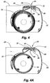
- the head rail 20 as seen best in Figs. 4 and 4A includes an arcuate main body 22 that depends downwardly from the front edge of an upper horizontal arm 24 with the arcuate main body lying in front of the roller 18 as viewed from the interior of a room in which the covering is mounted.
- the horizontal arm has a longitunally extending notch 26 formed in the back thereof defined by an upper ledge 28 and a lower ledge 30 with the upper ledge being slightly longer than the lower ledge so as to overlap the lower ledge along the rear edge of the head rail.
- the notch 26 in the rear edge of the head rail is adapted to cooperate with the roller stops 12 in releasably mounting the roller stops on the head rail as will be described in more detail hereafter.
- the shade material 16 illustrated has a bottom rail 32 affixed to the bottom edge thereof which becomes tangentially related to the roller 18 when the shade material is wrapped circumferentially about the roller as best seen in Figs. 4 and 4A.
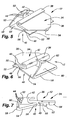
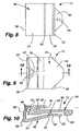
- the roller stop 12 is probably seen best in Figs. 5-10 to include a main body 34 having a plate like component 36 of generally trapezoidal configuration and a raised reverse turned upper lip 38 defining a recess 40 therebetween.
- the rear edge of the plate like component, or the edge having the reverse turned upper lip, has a rearwardly projecting vertically oriented tab 42 with vertically spaced serrated teeth 44 along its rear edge.
- a secondary body 46 of the roller stop is spaced beneath the main body 34 by a transverse web 48 of the main body with the secondary body having a forwardly projecting lower lip 50 spaced beneath in generally parallel relationship with the plate like component 36 of the main body.
- the forward most edge of the lower lip is beveled and defines a latch finger 52 for a purpose to be described hereafter.
- Projecting rearwardly from the transverse web 48 in generally co-planar relationship with the lower lip is a plate like component 54 of the secondary body which is connected to the transverse web of the main body with a pivot or hinge 56.
- An abutment edge 58 is defined at the rear edge of the plate like component 54 of the secondary body with the abutment edge being parallel to the pivot or hinge 56.
- a plate like catch arm 60 projects substantially perpendicularly upwardly from the plate like portion of the secondary body but in reality at an obtuse angle approaching 90°.
- the catch arm has a catch lip 62 projecting forwardly from its upper edge immediately adjacent to the serrated teeth 44 on the main body.
- the hinge 56 permits the plate like component 54 of the secondary body and the catch arm 60 to pivot in a vertical plane about the hinge 56 and relative to the main body 34 in a manner such that the catch lip 62 can be removably positioned between selected ones of the serrated teeth thereby establishing a predetermined angle between the plate like component of the secondary body and the plate like component of the main body.
- the abutment edge of the secondary body is thereby moveable upwardly or downwardly to adjust the vertical spacing between the abutment edge and the plate like component of the main body.
- the plate like component 36 of the main body also has a downwardly projecting finger 64-that is transversely centered at the front edge of the plate like component, the function of which will be described hereafter.
- the plate like component 36 of the main body and the forwardly projecting lower lip 50 of the secondary body as well as the forwardly projecting upper lip 38 of the main body are designed to cooperate with the upper 28 and lower 30 ledges of the head rail 20 to releasably connect the roller stop 12 to the head rail in a position for limiting rotation of the roller 18 when the covering is fully retracted.
- the rear edge of the upper ledge 28 of the head rail is insertable into the recess 40 between the upper lip and the plate like component 36 of the main body as the main body is simultaneously inserted into the notch 26 between the upper and lower ledges of the head rail.
- the lower ledge has an upturned lip 66 along its rear edge adapted to cooperate with the latch finger 52 of the secondary body at a location rearwardly spaced from a raised bead 68 on the lower ledge.
- the raised bead on the lower ledge is vertically aligned with a depending bead 70 from the upper ledge such that the downwardly projecting finger 64 at the front edge of the main body can be pinched and thereby captured between the upper and lower beads.
- roller stop 12 is positively but releasably connected to the head rail 20 and can be positioned at any location along the length of the head rail. Any number of roller stops can be utilized depending upon the width of the covering on which the roller stops are mounted, but in the illustrated embodiment, two of the roller stops are used and mounted at locations spaced inwardly from opposite ends of the head rail.
- the roller stop 12 can be made of any suitable material, but in the preferred embodiment, the roller stop is made of a somewhat rigid plastic material having some flexibility depending upon the thickness of the material. In other words, at the locations where it is desired that the plastic material be more rigid, it is made relatively thick, but where it is desired to flex it is made relatively thin.
- the pivot or hinge 56 is defined by a relatively thin segment of the roller stop 12 so that the relatively thin material at the pivot defines a living hinge permitting the plate like component 54 of the secondary body to pivot about the living hinge.
- pivotal movement of the plate like component of the secondary body permits the catch lip 62 to be positioned between any desirable pair of serrated teeth 44 so the plate like component of the secondary body is selectively retained at an angle relative to the main body which positions the abutment edge 58 of the secondary body at a desired vertical spacing from the main body.
- the desired positioning of the plate like component 54 of the secondary body is determined by the thickness of the wrap of shade material 16 on the roller which of course is determined by the length or vertical extent of the shade material when extended as shown in Fig. 1.
- the bottom rail 32 of the shade material is shown engaged with the abutment edge 58 of the roller stop.
- the abutment edge is thus positioned through the interaction of the catch lip 62 with the serrated teeth 44 so that it is closely adjacent to but spaced from the shade material when the covering is fully retracted.
- the abutment edge is positioned, however, close enough to the shade material so as to engage the bottom rail and prevent further rotation of the roller.
- Figs. 4 and 4A are illustrative of two different positions of the abutment edge of the secondary body to accommodate a relatively thick wrap (Fig. 4) or a relatively thin wrap (Fig. 4A).
- the roller stop 12 can be easily removed from a head rail by simply pushing upwardly on the lower lip 50 of the secondary body to release the latch finger 52 from the upturned lip 66 and the angular positioning of the plate like component 54 of the secondary body is easily movable simply by flexing the catch arm 60 and repositioning the catch arm between a different selected pair of serrated teeth 40.
- roller stop of the present invention can be very inexpensively manufactured in a one piece construction and easily mounted on or removed from the head rail of a covering for architectural openings. It is further easily and dependably adjustable to accommodate rolled fabrics of different dimensions.
Landscapes
- Engineering & Computer Science (AREA)
- Structural Engineering (AREA)
- Architecture (AREA)
- Civil Engineering (AREA)
- Operating, Guiding And Securing Of Roll- Type Closing Members (AREA)
- Blinds (AREA)
- Bag Frames (AREA)
Applications Claiming Priority (2)
| Application Number | Priority Date | Filing Date | Title |
|---|---|---|---|
| US72502605P | 2005-10-07 | 2005-10-07 | |
| US11/537,079 US7500505B2 (en) | 2005-10-07 | 2006-09-29 | Roller stop for coverings for architectural openings |
Publications (3)
| Publication Number | Publication Date |
|---|---|
| EP1783321A2 true EP1783321A2 (de) | 2007-05-09 |
| EP1783321A3 EP1783321A3 (de) | 2010-02-17 |
| EP1783321B1 EP1783321B1 (de) | 2011-11-23 |
Family
ID=37888015
Family Applications (1)
| Application Number | Title | Priority Date | Filing Date |
|---|---|---|---|
| EP06255137A Not-in-force EP1783321B1 (de) | 2005-10-07 | 2006-10-05 | Stopp für Rollo |
Country Status (6)
| Country | Link |
|---|---|
| US (1) | US7500505B2 (de) |
| EP (1) | EP1783321B1 (de) |
| AT (1) | ATE534794T1 (de) |
| AU (1) | AU2006225202B2 (de) |
| CA (1) | CA2562383C (de) |
| DK (1) | DK1783321T3 (de) |
Families Citing this family (32)
| Publication number | Priority date | Publication date | Assignee | Title |
|---|---|---|---|---|
| USD632493S1 (en) | 2003-08-20 | 2011-02-15 | Hunter Douglas Inc. | Retractable cellular fabric with cells of a drooped configuration |
| US7549455B2 (en) * | 2003-08-20 | 2009-06-23 | Hunter Douglas Inc. | Retractable shade with collapsible vanes |
| DK1664471T3 (en) | 2003-08-20 | 2019-03-18 | Hunter Douglas | Retractable roller blind with folding slats |
| US8393080B2 (en) | 2003-08-20 | 2013-03-12 | Hunter Douglas Inc. | Method for making a window covering having operable vanes |
| KR20140071489A (ko) * | 2004-08-20 | 2014-06-11 | 헌터더글라스인코포레이티드 | 작동가능한 베인을 갖는 윈도우 커버링 제조 장치 및 방법 |
| USD622964S1 (en) | 2004-08-20 | 2010-09-07 | Hunter Douglas Inc. | Retractable cellular fabric with right angle triangular cells having arcuate vanes |
| US7617858B2 (en) * | 2006-05-23 | 2009-11-17 | Hunter Douglas Inc. | Skew adjustment device for coverings for architectural openings |
| US7740044B2 (en) * | 2006-08-31 | 2010-06-22 | Dometic, LLC | Awning assembly including drop-down shade |
| KR100699769B1 (ko) * | 2006-11-24 | 2007-03-28 | 차기철 | 경사 및 위사의 연결방법으로 재직되는 블라인드 |
| US8261807B2 (en) | 2008-04-28 | 2012-09-11 | Hunter Douglas Inc. | Dual fabric covering for architectural openings |
| ES2766261T3 (es) * | 2009-05-18 | 2020-06-12 | Youil Corp Co Ltd | Tejido tridimensional con estructura de tres capas |
| CA2722375C (en) | 2009-12-02 | 2019-06-11 | Hunter Douglas Inc. | Collapsible vane structure and related method for a shade for an architectural opening |
| WO2011119333A1 (en) | 2010-03-23 | 2011-09-29 | Hunter Douglas Inc. | System for biasing fabric to gather in predetermined direction |
| CN105818366B (zh) | 2010-04-16 | 2018-06-15 | 亨特道格拉斯公司 | 用于制造卷帘的工序和系统 |
| CA2801901C (en) | 2010-06-08 | 2019-04-23 | Hunter Douglas Inc. | A unitary assembly for an architectural fenestration, providing dynamic solar heat gain control |
| USD748409S1 (en) * | 2011-05-16 | 2016-02-02 | Mario M. Marocco | Double blind |
| CA2844513C (en) | 2011-08-26 | 2019-10-29 | Hunter Douglas Inc. | Double pleat cellular shade with vanes |
| US8684062B2 (en) * | 2012-08-16 | 2014-04-01 | Philip Ng | Roller blind control mechanism |
| US9567802B2 (en) | 2013-03-15 | 2017-02-14 | Hunter Douglas Inc. | Covering for an architectural opening having nested rollers |
| US9963935B2 (en) | 2013-03-15 | 2018-05-08 | Hunter Douglas Inc. | Position lock for roller supported architectural coverings |
| US9945177B2 (en) | 2013-03-15 | 2018-04-17 | Hunter Douglas Inc. | Covering for an architectural opening having nested rollers |
| WO2015017842A2 (en) | 2013-08-02 | 2015-02-05 | Lutron Electronics Co., Inc. | Motorized sheer shading system |
| US9347261B2 (en) * | 2013-08-02 | 2016-05-24 | Lutron Electronics Co., Inc. | Adjustment mechanisms for shades |
| US9322210B2 (en) * | 2013-08-19 | 2016-04-26 | Comfortex Window Fashions | Cordless fabric venetian window shade assembly |
| KR101359513B1 (ko) | 2013-08-27 | 2014-02-07 | 곽재석 | 이중원단 블라인드의 원단 각도 조절장치 |
| US9702187B2 (en) | 2015-02-13 | 2017-07-11 | Hunter Douglas Inc. | Covering for an architectural opening having nested tubes |
| AU360867S (en) * | 2015-02-20 | 2015-03-31 | Acmeda Pty Ltd | Cassette assembly for a blind system |
| JP6550273B2 (ja) * | 2015-04-14 | 2019-07-24 | 立川ブラインド工業株式会社 | ロールスクリーン |
| JP6678398B2 (ja) * | 2015-04-28 | 2020-04-08 | 立川ブラインド工業株式会社 | ロールスクリーン |
| US10648229B2 (en) | 2016-06-30 | 2020-05-12 | Hunter Douglas Inc. | Architectural covering and method of manufacturing |
| AU2019204071B2 (en) | 2018-06-12 | 2025-04-03 | Hunter Douglas Inc. | Limited stop assembly for an architectural-structure covering |
| US12480345B1 (en) | 2025-08-15 | 2025-11-25 | Cltc Llc | Integrated bracket assembly with head stop for overhead doors |
Family Cites Families (12)
| Publication number | Priority date | Publication date | Assignee | Title |
|---|---|---|---|---|
| US588848A (en) * | 1897-08-24 | Bag-fastener | ||
| US4881707A (en) * | 1989-02-23 | 1989-11-21 | Clamp Swing Pricing Co. | Sign holder device |
| US5131616A (en) * | 1990-10-22 | 1992-07-21 | Graber Industries, Inc. | Bracket for adjustably supporting a headrail |
| NL9300531A (nl) * | 1993-03-24 | 1994-10-17 | Forest Group Nederland Bv | Glijder voor een gordijnrail. |
| US5383739A (en) * | 1993-06-15 | 1995-01-24 | Haglund; Vernon | Variable angle post for coupling fence segments |
| GB9604530D0 (en) * | 1996-03-02 | 1996-05-01 | Watson Paul L | Safety devices for doors |
| US5918842A (en) * | 1996-09-05 | 1999-07-06 | Garfinkle; Benjamin L. | Fixture tag molding adapter |
| US5697589A (en) * | 1996-09-05 | 1997-12-16 | Garfinkle; Benjamin L. | Fixture tag molding adapter |
| US6027091A (en) * | 1998-02-17 | 2000-02-22 | Johnson; Scott A. | Curtain clip |
| CA2276071C (en) * | 1998-06-22 | 2007-09-04 | Hunter Douglas Inc. | Remote control operating system and support structure for a retractable covering for an architectural opening |
| TWI260363B (en) * | 2003-12-09 | 2006-08-21 | Nien Made Entpr Co Ltd | Window shades control mechanism and control method thereof |
| US7240715B2 (en) * | 2003-12-24 | 2007-07-10 | Hunter Douglas Inc. | Limit stop for coverings for architectural openings |
-
2006
- 2006-09-29 US US11/537,079 patent/US7500505B2/en active Active
- 2006-10-03 AU AU2006225202A patent/AU2006225202B2/en not_active Ceased
- 2006-10-03 CA CA2562383A patent/CA2562383C/en not_active Expired - Fee Related
- 2006-10-05 DK DK06255137.9T patent/DK1783321T3/da active
- 2006-10-05 EP EP06255137A patent/EP1783321B1/de not_active Not-in-force
- 2006-10-05 AT AT06255137T patent/ATE534794T1/de active
Also Published As
| Publication number | Publication date |
|---|---|
| DK1783321T3 (da) | 2012-03-19 |
| CA2562383C (en) | 2013-07-23 |
| ATE534794T1 (de) | 2011-12-15 |
| US7500505B2 (en) | 2009-03-10 |
| EP1783321A3 (de) | 2010-02-17 |
| AU2006225202B2 (en) | 2011-03-10 |
| US20070079943A1 (en) | 2007-04-12 |
| AU2006225202A1 (en) | 2007-04-26 |
| EP1783321B1 (de) | 2011-11-23 |
| CA2562383A1 (en) | 2007-04-07 |
Similar Documents
| Publication | Publication Date | Title |
|---|---|---|
| EP1783321B1 (de) | Stopp für Rollo | |
| CA2677906C (en) | Lock lever mounting bracket for headrails on coverings for architectural openings | |
| US7134469B2 (en) | Headrail mounting system | |
| CA2174917C (en) | Control and suspension system for a vertical vane covering for architectural openings | |
| US7617858B2 (en) | Skew adjustment device for coverings for architectural openings | |
| US20170022757A1 (en) | Light Blocking Slatted Blind | |
| JP2005511928A (ja) | スライドスクリーンの縁部シール | |
| US7240715B2 (en) | Limit stop for coverings for architectural openings | |
| US4651795A (en) | Pleated fabric window covering cord lock | |
| US6499709B1 (en) | Bracket for supporting a powered window shade | |
| AU597863B2 (en) | Support for an operating element of a venetian blind assembly | |
| US6659154B2 (en) | Valance with adjustable mounting features | |
| US20070175594A1 (en) | Coverings for architectural openings with cord lock | |
| EP0775243B1 (de) | Verbessertes steuer- und aufhängungssystem für eine vertikallamellen-abdeckung für gebäudeöffnungen | |
| WO1996035855A9 (en) | A control and suspension system for a vertical vane covering for architectural openings | |
| TWI436751B (zh) | 捲簾 | |
| US7513294B2 (en) | System for suspending non-retractable shades in architectural openings | |
| CN215761423U (zh) | 一种窗帘升降系统以及窗帘 | |
| US20040226667A1 (en) | Mounting bracket and headrail for a window covering | |
| JPH0519023Y2 (de) |
Legal Events
| Date | Code | Title | Description |
|---|---|---|---|
| PUAI | Public reference made under article 153(3) epc to a published international application that has entered the european phase |
Free format text: ORIGINAL CODE: 0009012 |
|
| AK | Designated contracting states |
Kind code of ref document: A2 Designated state(s): AT BE BG CH CY CZ DE DK EE ES FI FR GB GR HU IE IS IT LI LT LU LV MC NL PL PT RO SE SI SK TR |
|
| AX | Request for extension of the european patent |
Extension state: AL BA HR MK YU |
|
| PUAL | Search report despatched |
Free format text: ORIGINAL CODE: 0009013 |
|
| AK | Designated contracting states |
Kind code of ref document: A3 Designated state(s): AT BE BG CH CY CZ DE DK EE ES FI FR GB GR HU IE IS IT LI LT LU LV MC NL PL PT RO SE SI SK TR |
|
| AX | Request for extension of the european patent |
Extension state: AL BA HR MK RS |
|
| 17P | Request for examination filed |
Effective date: 20100816 |
|
| AKX | Designation fees paid |
Designated state(s): AT BE BG CH CY CZ DE DK EE ES FI FR GB GR HU IE IS IT LI LT LU LV MC NL PL PT RO SE SI SK TR |
|
| GRAP | Despatch of communication of intention to grant a patent |
Free format text: ORIGINAL CODE: EPIDOSNIGR1 |
|
| GRAS | Grant fee paid |
Free format text: ORIGINAL CODE: EPIDOSNIGR3 |
|
| GRAA | (expected) grant |
Free format text: ORIGINAL CODE: 0009210 |
|
| AK | Designated contracting states |
Kind code of ref document: B1 Designated state(s): AT BE BG CH CY CZ DE DK EE ES FI FR GB GR HU IE IS IT LI LT LU LV MC NL PL PT RO SE SI SK TR |
|
| REG | Reference to a national code |
Ref country code: GB Ref legal event code: FG4D |
|
| REG | Reference to a national code |
Ref country code: CH Ref legal event code: EP |
|
| REG | Reference to a national code |
Ref country code: IE Ref legal event code: FG4D |
|
| REG | Reference to a national code |
Ref country code: NL Ref legal event code: T3 |
|
| REG | Reference to a national code |
Ref country code: DE Ref legal event code: R096 Ref document number: 602006025985 Country of ref document: DE Effective date: 20120209 |
|
| REG | Reference to a national code |
Ref country code: DK Ref legal event code: T3 |
|
| LTIE | Lt: invalidation of european patent or patent extension |
Effective date: 20111123 |
|
| PG25 | Lapsed in a contracting state [announced via postgrant information from national office to epo] |
Ref country code: IS Free format text: LAPSE BECAUSE OF FAILURE TO SUBMIT A TRANSLATION OF THE DESCRIPTION OR TO PAY THE FEE WITHIN THE PRESCRIBED TIME-LIMIT Effective date: 20120323 Ref country code: LT Free format text: LAPSE BECAUSE OF FAILURE TO SUBMIT A TRANSLATION OF THE DESCRIPTION OR TO PAY THE FEE WITHIN THE PRESCRIBED TIME-LIMIT Effective date: 20111123 |
|
| PG25 | Lapsed in a contracting state [announced via postgrant information from national office to epo] |
Ref country code: SI Free format text: LAPSE BECAUSE OF FAILURE TO SUBMIT A TRANSLATION OF THE DESCRIPTION OR TO PAY THE FEE WITHIN THE PRESCRIBED TIME-LIMIT Effective date: 20111123 Ref country code: GR Free format text: LAPSE BECAUSE OF FAILURE TO SUBMIT A TRANSLATION OF THE DESCRIPTION OR TO PAY THE FEE WITHIN THE PRESCRIBED TIME-LIMIT Effective date: 20120224 Ref country code: SE Free format text: LAPSE BECAUSE OF FAILURE TO SUBMIT A TRANSLATION OF THE DESCRIPTION OR TO PAY THE FEE WITHIN THE PRESCRIBED TIME-LIMIT Effective date: 20111123 Ref country code: PT Free format text: LAPSE BECAUSE OF FAILURE TO SUBMIT A TRANSLATION OF THE DESCRIPTION OR TO PAY THE FEE WITHIN THE PRESCRIBED TIME-LIMIT Effective date: 20120323 Ref country code: LV Free format text: LAPSE BECAUSE OF FAILURE TO SUBMIT A TRANSLATION OF THE DESCRIPTION OR TO PAY THE FEE WITHIN THE PRESCRIBED TIME-LIMIT Effective date: 20111123 |
|
| PG25 | Lapsed in a contracting state [announced via postgrant information from national office to epo] |
Ref country code: CY Free format text: LAPSE BECAUSE OF FAILURE TO SUBMIT A TRANSLATION OF THE DESCRIPTION OR TO PAY THE FEE WITHIN THE PRESCRIBED TIME-LIMIT Effective date: 20111123 |
|
| PG25 | Lapsed in a contracting state [announced via postgrant information from national office to epo] |
Ref country code: BG Free format text: LAPSE BECAUSE OF FAILURE TO SUBMIT A TRANSLATION OF THE DESCRIPTION OR TO PAY THE FEE WITHIN THE PRESCRIBED TIME-LIMIT Effective date: 20120223 Ref country code: CZ Free format text: LAPSE BECAUSE OF FAILURE TO SUBMIT A TRANSLATION OF THE DESCRIPTION OR TO PAY THE FEE WITHIN THE PRESCRIBED TIME-LIMIT Effective date: 20111123 Ref country code: EE Free format text: LAPSE BECAUSE OF FAILURE TO SUBMIT A TRANSLATION OF THE DESCRIPTION OR TO PAY THE FEE WITHIN THE PRESCRIBED TIME-LIMIT Effective date: 20111123 Ref country code: SK Free format text: LAPSE BECAUSE OF FAILURE TO SUBMIT A TRANSLATION OF THE DESCRIPTION OR TO PAY THE FEE WITHIN THE PRESCRIBED TIME-LIMIT Effective date: 20111123 |
|
| PG25 | Lapsed in a contracting state [announced via postgrant information from national office to epo] |
Ref country code: RO Free format text: LAPSE BECAUSE OF FAILURE TO SUBMIT A TRANSLATION OF THE DESCRIPTION OR TO PAY THE FEE WITHIN THE PRESCRIBED TIME-LIMIT Effective date: 20111123 Ref country code: IT Free format text: LAPSE BECAUSE OF FAILURE TO SUBMIT A TRANSLATION OF THE DESCRIPTION OR TO PAY THE FEE WITHIN THE PRESCRIBED TIME-LIMIT Effective date: 20111123 Ref country code: PL Free format text: LAPSE BECAUSE OF FAILURE TO SUBMIT A TRANSLATION OF THE DESCRIPTION OR TO PAY THE FEE WITHIN THE PRESCRIBED TIME-LIMIT Effective date: 20111123 |
|
| REG | Reference to a national code |
Ref country code: AT Ref legal event code: MK05 Ref document number: 534794 Country of ref document: AT Kind code of ref document: T Effective date: 20111123 |
|
| PLBE | No opposition filed within time limit |
Free format text: ORIGINAL CODE: 0009261 |
|
| STAA | Information on the status of an ep patent application or granted ep patent |
Free format text: STATUS: NO OPPOSITION FILED WITHIN TIME LIMIT |
|
| 26N | No opposition filed |
Effective date: 20120824 |
|
| REG | Reference to a national code |
Ref country code: DE Ref legal event code: R097 Ref document number: 602006025985 Country of ref document: DE Effective date: 20120824 |
|
| PG25 | Lapsed in a contracting state [announced via postgrant information from national office to epo] |
Ref country code: AT Free format text: LAPSE BECAUSE OF FAILURE TO SUBMIT A TRANSLATION OF THE DESCRIPTION OR TO PAY THE FEE WITHIN THE PRESCRIBED TIME-LIMIT Effective date: 20111123 |
|
| PG25 | Lapsed in a contracting state [announced via postgrant information from national office to epo] |
Ref country code: MC Free format text: LAPSE BECAUSE OF NON-PAYMENT OF DUE FEES Effective date: 20121031 |
|
| REG | Reference to a national code |
Ref country code: CH Ref legal event code: PL |
|
| PG25 | Lapsed in a contracting state [announced via postgrant information from national office to epo] |
Ref country code: FI Free format text: LAPSE BECAUSE OF FAILURE TO SUBMIT A TRANSLATION OF THE DESCRIPTION OR TO PAY THE FEE WITHIN THE PRESCRIBED TIME-LIMIT Effective date: 20111123 |
|
| REG | Reference to a national code |
Ref country code: IE Ref legal event code: MM4A |
|
| PG25 | Lapsed in a contracting state [announced via postgrant information from national office to epo] |
Ref country code: IE Free format text: LAPSE BECAUSE OF NON-PAYMENT OF DUE FEES Effective date: 20121005 Ref country code: LI Free format text: LAPSE BECAUSE OF NON-PAYMENT OF DUE FEES Effective date: 20121031 Ref country code: CH Free format text: LAPSE BECAUSE OF NON-PAYMENT OF DUE FEES Effective date: 20121031 |
|
| PG25 | Lapsed in a contracting state [announced via postgrant information from national office to epo] |
Ref country code: ES Free format text: LAPSE BECAUSE OF FAILURE TO SUBMIT A TRANSLATION OF THE DESCRIPTION OR TO PAY THE FEE WITHIN THE PRESCRIBED TIME-LIMIT Effective date: 20120305 |
|
| PG25 | Lapsed in a contracting state [announced via postgrant information from national office to epo] |
Ref country code: TR Free format text: LAPSE BECAUSE OF FAILURE TO SUBMIT A TRANSLATION OF THE DESCRIPTION OR TO PAY THE FEE WITHIN THE PRESCRIBED TIME-LIMIT Effective date: 20111123 |
|
| PG25 | Lapsed in a contracting state [announced via postgrant information from national office to epo] |
Ref country code: LU Free format text: LAPSE BECAUSE OF NON-PAYMENT OF DUE FEES Effective date: 20121005 |
|
| PG25 | Lapsed in a contracting state [announced via postgrant information from national office to epo] |
Ref country code: HU Free format text: LAPSE BECAUSE OF FAILURE TO SUBMIT A TRANSLATION OF THE DESCRIPTION OR TO PAY THE FEE WITHIN THE PRESCRIBED TIME-LIMIT Effective date: 20061005 |
|
| REG | Reference to a national code |
Ref country code: FR Ref legal event code: PLFP Year of fee payment: 11 |
|
| REG | Reference to a national code |
Ref country code: FR Ref legal event code: PLFP Year of fee payment: 12 |
|
| REG | Reference to a national code |
Ref country code: FR Ref legal event code: PLFP Year of fee payment: 13 |
|
| PGFP | Annual fee paid to national office [announced via postgrant information from national office to epo] |
Ref country code: FR Payment date: 20200914 Year of fee payment: 15 Ref country code: GB Payment date: 20200923 Year of fee payment: 15 |
|
| PGFP | Annual fee paid to national office [announced via postgrant information from national office to epo] |
Ref country code: BE Payment date: 20200916 Year of fee payment: 15 |
|
| PGFP | Annual fee paid to national office [announced via postgrant information from national office to epo] |
Ref country code: NL Payment date: 20201015 Year of fee payment: 15 |
|
| PGFP | Annual fee paid to national office [announced via postgrant information from national office to epo] |
Ref country code: DK Payment date: 20201012 Year of fee payment: 15 Ref country code: DE Payment date: 20200922 Year of fee payment: 15 |
|
| REG | Reference to a national code |
Ref country code: DE Ref legal event code: R119 Ref document number: 602006025985 Country of ref document: DE |
|
| REG | Reference to a national code |
Ref country code: DK Ref legal event code: EBP Effective date: 20211031 |
|
| REG | Reference to a national code |
Ref country code: NL Ref legal event code: MM Effective date: 20211101 |
|
| REG | Reference to a national code |
Ref country code: BE Ref legal event code: MM Effective date: 20211031 |
|
| GBPC | Gb: european patent ceased through non-payment of renewal fee |
Effective date: 20211005 |
|
| PG25 | Lapsed in a contracting state [announced via postgrant information from national office to epo] |
Ref country code: NL Free format text: LAPSE BECAUSE OF NON-PAYMENT OF DUE FEES Effective date: 20211101 Ref country code: GB Free format text: LAPSE BECAUSE OF NON-PAYMENT OF DUE FEES Effective date: 20211005 Ref country code: DE Free format text: LAPSE BECAUSE OF NON-PAYMENT OF DUE FEES Effective date: 20220503 Ref country code: BE Free format text: LAPSE BECAUSE OF NON-PAYMENT OF DUE FEES Effective date: 20211031 |
|
| PG25 | Lapsed in a contracting state [announced via postgrant information from national office to epo] |
Ref country code: FR Free format text: LAPSE BECAUSE OF NON-PAYMENT OF DUE FEES Effective date: 20211031 |
|
| PG25 | Lapsed in a contracting state [announced via postgrant information from national office to epo] |
Ref country code: DK Free format text: LAPSE BECAUSE OF NON-PAYMENT OF DUE FEES Effective date: 20211031 |