EP1783327A2 - Refroidissement avec microcanaux périphériques en serpentin pour aube de turbine - Google Patents
Refroidissement avec microcanaux périphériques en serpentin pour aube de turbine Download PDFInfo
- Publication number
- EP1783327A2 EP1783327A2 EP06255628A EP06255628A EP1783327A2 EP 1783327 A2 EP1783327 A2 EP 1783327A2 EP 06255628 A EP06255628 A EP 06255628A EP 06255628 A EP06255628 A EP 06255628A EP 1783327 A2 EP1783327 A2 EP 1783327A2
- Authority
- EP
- European Patent Office
- Prior art keywords
- cooling
- leg
- serpentine
- turbine engine
- engine component
- Prior art date
- Legal status (The legal status is an assumption and is not a legal conclusion. Google has not performed a legal analysis and makes no representation as to the accuracy of the status listed.)
- Granted
Links
Images

Classifications
-
- F—MECHANICAL ENGINEERING; LIGHTING; HEATING; WEAPONS; BLASTING
- F01—MACHINES OR ENGINES IN GENERAL; ENGINE PLANTS IN GENERAL; STEAM ENGINES
- F01D—NON-POSITIVE DISPLACEMENT MACHINES OR ENGINES, e.g. STEAM TURBINES
- F01D5/00—Blades; Blade-carrying members; Heating, heat-insulating, cooling or antivibration means on the blades or the members
- F01D5/12—Blades
- F01D5/14—Form or construction
- F01D5/18—Hollow blades, i.e. blades with cooling or heating channels or cavities; Heating, heat-insulating or cooling means on blades
-
- F—MECHANICAL ENGINEERING; LIGHTING; HEATING; WEAPONS; BLASTING
- F01—MACHINES OR ENGINES IN GENERAL; ENGINE PLANTS IN GENERAL; STEAM ENGINES
- F01D—NON-POSITIVE DISPLACEMENT MACHINES OR ENGINES, e.g. STEAM TURBINES
- F01D5/00—Blades; Blade-carrying members; Heating, heat-insulating, cooling or antivibration means on the blades or the members
- F01D5/12—Blades
- F01D5/14—Form or construction
- F01D5/18—Hollow blades, i.e. blades with cooling or heating channels or cavities; Heating, heat-insulating or cooling means on blades
- F01D5/187—Convection cooling
-
- B—PERFORMING OPERATIONS; TRANSPORTING
- B22—CASTING; POWDER METALLURGY
- B22C—FOUNDRY MOULDING
- B22C9/00—Moulds or cores; Moulding processes
- B22C9/02—Sand moulds or like moulds for shaped castings
- B22C9/04—Use of lost patterns
-
- B—PERFORMING OPERATIONS; TRANSPORTING
- B22—CASTING; POWDER METALLURGY
- B22C—FOUNDRY MOULDING
- B22C9/00—Moulds or cores; Moulding processes
- B22C9/10—Cores; Manufacture or installation of cores
- B22C9/103—Multipart cores
-
- F—MECHANICAL ENGINEERING; LIGHTING; HEATING; WEAPONS; BLASTING
- F01—MACHINES OR ENGINES IN GENERAL; ENGINE PLANTS IN GENERAL; STEAM ENGINES
- F01D—NON-POSITIVE DISPLACEMENT MACHINES OR ENGINES, e.g. STEAM TURBINES
- F01D5/00—Blades; Blade-carrying members; Heating, heat-insulating, cooling or antivibration means on the blades or the members
-
- F—MECHANICAL ENGINEERING; LIGHTING; HEATING; WEAPONS; BLASTING
- F01—MACHINES OR ENGINES IN GENERAL; ENGINE PLANTS IN GENERAL; STEAM ENGINES
- F01D—NON-POSITIVE DISPLACEMENT MACHINES OR ENGINES, e.g. STEAM TURBINES
- F01D5/00—Blades; Blade-carrying members; Heating, heat-insulating, cooling or antivibration means on the blades or the members
- F01D5/12—Blades
- F01D5/14—Form or construction
-
- F—MECHANICAL ENGINEERING; LIGHTING; HEATING; WEAPONS; BLASTING
- F05—INDEXING SCHEMES RELATING TO ENGINES OR PUMPS IN VARIOUS SUBCLASSES OF CLASSES F01-F04
- F05D—INDEXING SCHEME FOR ASPECTS RELATING TO NON-POSITIVE-DISPLACEMENT MACHINES OR ENGINES, GAS-TURBINES OR JET-PROPULSION PLANTS
- F05D2230/00—Manufacture
- F05D2230/20—Manufacture essentially without removing material
- F05D2230/21—Manufacture essentially without removing material by casting
- F05D2230/211—Manufacture essentially without removing material by casting by precision casting, e.g. microfusing or investment casting
-
- F—MECHANICAL ENGINEERING; LIGHTING; HEATING; WEAPONS; BLASTING
- F05—INDEXING SCHEMES RELATING TO ENGINES OR PUMPS IN VARIOUS SUBCLASSES OF CLASSES F01-F04
- F05D—INDEXING SCHEME FOR ASPECTS RELATING TO NON-POSITIVE-DISPLACEMENT MACHINES OR ENGINES, GAS-TURBINES OR JET-PROPULSION PLANTS
- F05D2250/00—Geometry
- F05D2250/10—Two-dimensional
- F05D2250/18—Two-dimensional patterned
- F05D2250/185—Two-dimensional patterned serpentine-like
-
- F—MECHANICAL ENGINEERING; LIGHTING; HEATING; WEAPONS; BLASTING
- F28—HEAT EXCHANGE IN GENERAL
- F28F—DETAILS OF HEAT-EXCHANGE AND HEAT-TRANSFER APPARATUS, OF GENERAL APPLICATION
- F28F13/00—Arrangements for modifying heat-transfer, e.g. increasing, decreasing
- F28F13/06—Arrangements for modifying heat-transfer, e.g. increasing, decreasing by affecting the pattern of flow of the heat-exchange media
-
- F—MECHANICAL ENGINEERING; LIGHTING; HEATING; WEAPONS; BLASTING
- F28—HEAT EXCHANGE IN GENERAL
- F28F—DETAILS OF HEAT-EXCHANGE AND HEAT-TRANSFER APPARATUS, OF GENERAL APPLICATION
- F28F3/00—Plate-like or laminated elements; Assemblies of plate-like or laminated elements
- F28F3/02—Elements or assemblies thereof with means for increasing heat-transfer area, e.g. with fins, with recesses, with corrugations
- F28F3/022—Elements or assemblies thereof with means for increasing heat-transfer area, e.g. with fins, with recesses, with corrugations the means being wires or pins
-
- F—MECHANICAL ENGINEERING; LIGHTING; HEATING; WEAPONS; BLASTING
- F28—HEAT EXCHANGE IN GENERAL
- F28F—DETAILS OF HEAT-EXCHANGE AND HEAT-TRANSFER APPARATUS, OF GENERAL APPLICATION
- F28F3/00—Plate-like or laminated elements; Assemblies of plate-like or laminated elements
- F28F3/12—Elements constructed in the shape of a hollow panel, e.g. with channels
-
- Y—GENERAL TAGGING OF NEW TECHNOLOGICAL DEVELOPMENTS; GENERAL TAGGING OF CROSS-SECTIONAL TECHNOLOGIES SPANNING OVER SEVERAL SECTIONS OF THE IPC; TECHNICAL SUBJECTS COVERED BY FORMER USPC CROSS-REFERENCE ART COLLECTIONS [XRACs] AND DIGESTS
- Y02—TECHNOLOGIES OR APPLICATIONS FOR MITIGATION OR ADAPTATION AGAINST CLIMATE CHANGE
- Y02T—CLIMATE CHANGE MITIGATION TECHNOLOGIES RELATED TO TRANSPORTATION
- Y02T50/00—Aeronautics or air transport
- Y02T50/60—Efficient propulsion technologies, e.g. for aircraft
-
- Y—GENERAL TAGGING OF NEW TECHNOLOGICAL DEVELOPMENTS; GENERAL TAGGING OF CROSS-SECTIONAL TECHNOLOGIES SPANNING OVER SEVERAL SECTIONS OF THE IPC; TECHNICAL SUBJECTS COVERED BY FORMER USPC CROSS-REFERENCE ART COLLECTIONS [XRACs] AND DIGESTS
- Y10—TECHNICAL SUBJECTS COVERED BY FORMER USPC
- Y10T—TECHNICAL SUBJECTS COVERED BY FORMER US CLASSIFICATION
- Y10T29/00—Metal working
- Y10T29/49—Method of mechanical manufacture
- Y10T29/49316—Impeller making
- Y10T29/49336—Blade making
- Y10T29/49339—Hollow blade
- Y10T29/49341—Hollow blade with cooling passage
- Y10T29/49343—Passage contains tubular insert
Definitions
- the present invention relates to a peripheral microcircuit serpentine cooling scheme for use in airfoil portions of turbine engine components, particularly high pressure turbine blade airfoils.
- Gas turbine engines are frequently used for small military applications and helicopter applications.
- the gas turbine engines used in these applications have high pressure turbine blades whose airfoil portions require the use of cooling fluids due to the temperatures at which these engines are asked to perform.
- operating temperatures have increased to values above 3100 degrees Fahrenheit (1704°C).
- the airfoil portions require an improved cooling strategy.
- a turbine engine component has an airfoil portion which is provided with a cooling scheme which minimizes the use of cooling flow but increases the cooling efficiency.
- a turbine engine component in accordance with the present invention broadly comprises an airfoil portion having at least one central core element, a pressure side wall, and a suction side wall, and a serpentine cooling passageway in at least one of the walls.
- a serpentine cooling passageway is provided in each of the pressure and suction side walls.
- a refractory metal core for forming a cooling passageway in an airfoil portion of a turbine engine component is also provided in accordance with the present invention.
- the refractory metal core has a serpentine configuration.
- a process for forming an airfoil portion of a turbine engine component broadly comprises the steps of placing at least one silica core for forming a central core element in a die, placing at least one refractory metal core element for forming at least one serpentine cooling passageway in the die, and forming the turbine engine component by introducing a molten metal material into the die so that the metal material flows around the at least one silica core and the at least one refractory metal core element so as to form an airfoil portion having a pair of peripheral skin walls and at least one serpentine cooling passageway in one of the peripheral skin walls.
- peripheral microcircuit serpentine cooling for turbine airfoils are set forth in the following detailed description and the accompanying drawings wherein like reference numerals depict like elements.
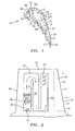
- FIG. 1 is a cross sectional view of an airfoil portion 10 of a turbine engine component such as a high pressure turbine blade or vane.
- the airfoil portion has a leading edge 60, a trailing edge 16, a pressure side 18, and a suction side 24.
- the airfoil portion 10 may be provided with three microcircuits for cooling.
- a first microcircuit 14 may be used to cool the trailing edge 16 with one or more ejection slots 17 being located on the pressure side 18 of the airfoil portion 10.
- a second microcircuit 20 may be located on the pressure side 18 of the airfoil portion 10.
- a third microcircuit 22 may be located on the suction side 24 of the airfoil portion 10.
- the airfoil portion 10 has one or more central core elements 12.
- Each of the central core elements 12 communicates with a source (not shown) of cooling fluid, such as engine bleed air, via inlets (not shown).
- Peripheral skin walls 13 and 15 extend between the central core elements 12 and the external surface forming the pressure side 18 and the external surface forming the suction side 24.
- the second and third microcircuits 20 and 22 are each located in a respective one of the peripheral skin walls 13 and 15.
- each of the microcircuits 20 and 22 preferably has a serpentine type of arrangement with at least three legs through which a cooling fluid flows.
- the microcircuits 20 and 22 each may have any number of legs.
- cooling fluid may enter an inlet leg 30 through one or more inlets 31, flow through an intermediate leg 32, and exit outward from an outlet leg 34 via one or more cooling film holes or slots 33.
- the intermediate leg 32 may also be provided with cooling film slots (not shown) if desired.
- the inlet leg 30 may be provided with one or more internal features 36, such as rounded pedestals, to enhance the heat transfer characteristics of the microcircuit 20.
- the internal features 36 may be formed using any suitable technique known in the art.
- Each inlet 31 is preferably designed so as to force cooling air to flow into the inlet leg 30 in a direction at an angle of less than 25 degrees, preferably substantially normal, to the main cooling flow direction Y in the inlet leg 30.
- Each inlet 31 is in fluid communication with one of the core elements 12. Causing the inlet flow of cooling fluid to flow in a direction normal to the flow direction Y is particularly important to prevent sand or foreign matter from flowing into the cooling microcircuit 20.
- the cooling fluid enters an inlet leg 40 via one or more inlets 41, flows through an intermediate leg 42, and exits outwardly from an outlet leg 44 via film holes 45.
- the cooling film holes 45 are located ahead of the airfoil gauge external point 47. It has been found that by providing the cooling film holes 45 in this location, the film of cooling fluid better hugs the suction side external surface and thereby increases the effectiveness of the cooling caused by the serpentine passageway microcircuit 22.
- the inlet leg 40 may be provided with internal features 46, such as rounded pedestals, to enhance the heat transfer characteristics of the microcircuit 22.
- the internal features 46 may be fabricated using any suitable technique known in the art.
- the internal features 46 may be formed using a laser technique.
- Each inlet 41 is preferably designed so as to force cooling air to enter the inlet leg 40 in a direction at an angle of less than 25 degrees, preferably substantially normal, to the cooling flow direction Y in the inlet leg 40. As previously noted, this is particularly significant in preventing sand or foreign matter from being introduced into the cooling microcircuit 22.
- Each inlet 41 communicates with and receives cooling air from one of the central core elements 12.
- the central core element 12 feeding inlet 41 may be the same one as that feeding the inlet 31. In a preferred embodiment though, the inlet 31 and 41 are fed from different core elements 12. By doing this, the microcircuits 20 and 22 are independent of each other.
- the trailing edge microcircuit 14 may have its own supply of cooling fluid from one of the central core elements 12 or may share a supply cavity such as one of the central core elements 12 with the suction side microcircuit 22.
- the microcircuit 14 may be provided with an inlet (not shown) which causes the cooling fluid flow to turn to enter the cooling microcircuit. As a result, sand and debris will centrifuge out in the central core elements 12.
- the leading edge 60 of the airfoil portion 10 may be provided with a cooling microcircuit 62 which has a plurality of cooling film holes 64.
- the leading edge cooling microcircuit 62 may be supplied with its own cooling flow from its own supply cavity.
- the flow of cooling fluid in the microcircuit 20 may be in a first direction, such as toward the trailing edge 16 of the airfoil portion 10, while the flow of cooling fluid in the microcircuit 22 may be in a second direction toward the leading edge 60 of the airfoil portion. If desired, the flow of cooling fluid in both microcircuits 20 and 22 may be in a single direction.
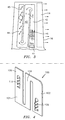
- Each of the microcircuits 20 and 22 are preferably formed using serpentine shaped refractory metal cores 100 such as that shown in FIG. 4.
- Each refractory metal core 100 may be formed from any suitable refractory metal known in the art such as a metal selected from the group consisting of molybdenum, tantalum, titanium, niobium, and alloys thereof.
- Each refractory metal core 100 is a sheet 101 of the refractory metal having portions bent out of the sheets to form structures such as the cooling fluid inlets and the film cooling holes.
- the exits of the refractory metal core 100 on the suction side has to be placed ahead of the airfoil gauge external point 47 for better performance of the microcircuit to be formed.
- the refractory metal core 100 may be placed close to the trailing edge 16 to protect the trailing edge microcircuit.
- Each metal core 100 used to form the microcircuits 20 and 22 may have a first section 102 for forming the inlet leg of the microcircuit, a second section 104 for forming the intermediate leg(s) of the microcircuit, and a third section 106 for forming the outlet leg of the microcircuit.
- the first section 102 may have one or more inwardly directed tabs 108 for forming one or more inlets.
- the third section 106 may have one or more outwardly directed tabs 110 for forming the cooling film holes.
- one or more silica cores 120 are positioned within a die 122. Also positioned within the die 122 are the refractory metal cores 100 with one on a suction side of the silica core(s) 120 and the other on a pressure side of the silica core(s). Appropriate core structures (not shown) may be used to form the leading edge and trailing edge microcircuits 62 and 14 respectively.
- molten metal material such as a molten nickel-based superalloy is introduced into the die 122 to form the airfoil portion 10 with the various ribs 124 separating the central core elements 12 and the peripheral skin walls 13 and 15.
- the silica core(s) 120 and the refractory metal cores 100 may be removed using any suitable technique known in the art. The remaining airfoil portion 10 is that shown in FIG. 1.
- silica cores 120 there are two silica cores 120 positioned within the die 122 separated by a rib to provide each of the refractory metal core circuits to independently avoid pressure biases between the refractory core metal core sink pressures.
- the silica cores 120 may be split further with communicating ribs.
- the microcircuits 20 and 22 are preferably formed with cooling passage legs which have a minimal cross sectional area.
- the cooling scheme of the present invention may reduce the flow of cooling fluid by 40%. That is, for this application, existing cooling configurations generally require 5.5% flow; whereas, with the configuration of the present invention, the cooling fluid flow could attain values as low as 3.3%. Other advantages to the present invention include increased convective efficiency and large film coverage leading to high overall cooling effectiveness of 75%.
Landscapes
- Engineering & Computer Science (AREA)
- Mechanical Engineering (AREA)
- General Engineering & Computer Science (AREA)
- Turbine Rotor Nozzle Sealing (AREA)
- Molds, Cores, And Manufacturing Methods Thereof (AREA)
Priority Applications (1)
| Application Number | Priority Date | Filing Date | Title |
|---|---|---|---|
| EP12185164A EP2543822A1 (fr) | 2005-11-08 | 2006-11-01 | Aube de turbine avec des microcanaux périphériques de refroidissement à serpentin |
Applications Claiming Priority (1)
| Application Number | Priority Date | Filing Date | Title |
|---|---|---|---|
| US11/269,030 US7744347B2 (en) | 2005-11-08 | 2005-11-08 | Peripheral microcircuit serpentine cooling for turbine airfoils |
Related Child Applications (1)
| Application Number | Title | Priority Date | Filing Date |
|---|---|---|---|
| EP12185164A Division-Into EP2543822A1 (fr) | 2005-11-08 | 2006-11-01 | Aube de turbine avec des microcanaux périphériques de refroidissement à serpentin |
Publications (3)
| Publication Number | Publication Date |
|---|---|
| EP1783327A2 true EP1783327A2 (fr) | 2007-05-09 |
| EP1783327A3 EP1783327A3 (fr) | 2010-11-03 |
| EP1783327B1 EP1783327B1 (fr) | 2018-02-28 |
Family
ID=37685205
Family Applications (2)
| Application Number | Title | Priority Date | Filing Date |
|---|---|---|---|
| EP12185164A Withdrawn EP2543822A1 (fr) | 2005-11-08 | 2006-11-01 | Aube de turbine avec des microcanaux périphériques de refroidissement à serpentin |
| EP06255628.7A Active EP1783327B1 (fr) | 2005-11-08 | 2006-11-01 | Noyau métallique réfractaire et procédé de fabrication pour aubes de turbine |
Family Applications Before (1)
| Application Number | Title | Priority Date | Filing Date |
|---|---|---|---|
| EP12185164A Withdrawn EP2543822A1 (fr) | 2005-11-08 | 2006-11-01 | Aube de turbine avec des microcanaux périphériques de refroidissement à serpentin |
Country Status (7)
| Country | Link |
|---|---|
| US (3) | US7744347B2 (fr) |
| EP (2) | EP2543822A1 (fr) |
| JP (1) | JP2007132342A (fr) |
| KR (1) | KR20070049552A (fr) |
| CN (1) | CN1963157A (fr) |
| SG (1) | SG132578A1 (fr) |
| TW (1) | TW200718859A (fr) |
Cited By (7)
| Publication number | Priority date | Publication date | Assignee | Title |
|---|---|---|---|---|
| EP1884621A2 (fr) | 2006-07-28 | 2008-02-06 | United Technologies Corporation | Refroidissement par microcircuit à serpentin avec des caractéristiques côtés pression |
| US8662825B2 (en) | 2009-09-09 | 2014-03-04 | Rolls-Royce Plc | Cooled aerofoil blade or vane |
| EP3067520A1 (fr) * | 2015-03-05 | 2016-09-14 | United Technologies Corporation | Composant de turbine à gaz comprenant un refroidissement en serpentin |
| EP3106616A1 (fr) * | 2015-05-08 | 2016-12-21 | United Technologies Corporation | Passage de refroidissement du noyau de peau axial d'un composant de moteur à turbine |
| US10502066B2 (en) | 2015-05-08 | 2019-12-10 | United Technologies Corporation | Turbine engine component including an axially aligned skin core passage interrupted by a pedestal |
| EP2876257B1 (fr) * | 2013-11-22 | 2020-01-01 | General Electric Company | Composant de turbine modifié et procédé de fabrication |
| EP3832069A1 (fr) | 2019-12-06 | 2021-06-09 | Siemens Aktiengesellschaft | Aube de turbine pour turbine à gaz fixe |
Families Citing this family (39)
| Publication number | Priority date | Publication date | Assignee | Title |
|---|---|---|---|---|
| US7744347B2 (en) * | 2005-11-08 | 2010-06-29 | United Technologies Corporation | Peripheral microcircuit serpentine cooling for turbine airfoils |
| US7364405B2 (en) * | 2005-11-23 | 2008-04-29 | United Technologies Corporation | Microcircuit cooling for vanes |
| CA126844S (en) | 2008-04-03 | 2009-06-22 | Adm 21 Co Ltd | Universal fit wiper blade |
| CA127205S (en) | 2008-05-07 | 2009-09-29 | Adm 21 Co Ltd | Windshield wiper blade |
| CA127208S (en) | 2008-05-07 | 2009-09-29 | Adm 21 Co Ltd | Windshield wiper blade |
| CA127207S (en) | 2008-05-07 | 2009-09-29 | Adm 21 Co Ltd | Windshield wiper blade |
| US8157527B2 (en) | 2008-07-03 | 2012-04-17 | United Technologies Corporation | Airfoil with tapered radial cooling passage |
| CA127703S (en) | 2008-07-28 | 2009-09-29 | Adm 21 Co Ltd | Windshield wiper blade |
| USD593023S1 (en) | 2008-07-28 | 2009-05-26 | Kim In-Kyu | Windshield wiper blade |
| CA127704S (en) | 2008-07-28 | 2009-09-29 | Adm 21 Co Ltd | Windshield wiper blade |
| US8572844B2 (en) | 2008-08-29 | 2013-11-05 | United Technologies Corporation | Airfoil with leading edge cooling passage |
| US8303252B2 (en) | 2008-10-16 | 2012-11-06 | United Technologies Corporation | Airfoil with cooling passage providing variable heat transfer rate |
| US8109725B2 (en) | 2008-12-15 | 2012-02-07 | United Technologies Corporation | Airfoil with wrapped leading edge cooling passage |
| US8371815B2 (en) * | 2010-03-17 | 2013-02-12 | General Electric Company | Apparatus for cooling an airfoil |
| US8562286B2 (en) * | 2010-04-06 | 2013-10-22 | United Technologies Corporation | Dead ended bulbed rib geometry for a gas turbine engine |
| US8535006B2 (en) | 2010-07-14 | 2013-09-17 | Siemens Energy, Inc. | Near-wall serpentine cooled turbine airfoil |
| US9022736B2 (en) | 2011-02-15 | 2015-05-05 | Siemens Energy, Inc. | Integrated axial and tangential serpentine cooling circuit in a turbine airfoil |
| US9017025B2 (en) | 2011-04-22 | 2015-04-28 | Siemens Energy, Inc. | Serpentine cooling circuit with T-shaped partitions in a turbine airfoil |
| US9879546B2 (en) | 2012-06-21 | 2018-01-30 | United Technologies Corporation | Airfoil cooling circuits |
| US10100646B2 (en) * | 2012-08-03 | 2018-10-16 | United Technologies Corporation | Gas turbine engine component cooling circuit |
| US9486854B2 (en) | 2012-09-10 | 2016-11-08 | United Technologies Corporation | Ceramic and refractory metal core assembly |
| ITCO20120061A1 (it) * | 2012-12-13 | 2014-06-14 | Nuovo Pignone Srl | Metodi per produrre pale di turbomacchina con canali sagomati mediante produzione additiva, pale di turbomacchina e turbomacchine |
| US9551228B2 (en) * | 2013-01-09 | 2017-01-24 | United Technologies Corporation | Airfoil and method of making |
| WO2014197061A2 (fr) * | 2013-03-15 | 2014-12-11 | United Technologies Corporation | Trou de refroidissement de film formé de turbine à gaz |
| US9797258B2 (en) * | 2013-10-23 | 2017-10-24 | General Electric Company | Turbine bucket including cooling passage with turn |
| US20150184538A1 (en) * | 2013-12-30 | 2015-07-02 | General Electric Company | Interior cooling circuits in turbine blades |
| US9897006B2 (en) * | 2015-06-15 | 2018-02-20 | General Electric Company | Hot gas path component cooling system having a particle collection chamber |
| US10801407B2 (en) | 2015-06-24 | 2020-10-13 | Raytheon Technologies Corporation | Core assembly for gas turbine engine |
| US10370978B2 (en) * | 2015-10-15 | 2019-08-06 | General Electric Company | Turbine blade |
| US20170306764A1 (en) * | 2016-04-26 | 2017-10-26 | General Electric Company | Airfoil for a turbine engine |
| US10605090B2 (en) * | 2016-05-12 | 2020-03-31 | General Electric Company | Intermediate central passage spanning outer walls aft of airfoil leading edge passage |
| US10119406B2 (en) * | 2016-05-12 | 2018-11-06 | General Electric Company | Blade with stress-reducing bulbous projection at turn opening of coolant passages |
| US10808571B2 (en) * | 2017-06-22 | 2020-10-20 | Raytheon Technologies Corporation | Gaspath component including minicore plenums |
| US10759539B2 (en) * | 2018-03-30 | 2020-09-01 | The Boeing Company | Heat exchanger for mitigating ice formation on an aircraft |
| US10808572B2 (en) * | 2018-04-02 | 2020-10-20 | General Electric Company | Cooling structure for a turbomachinery component |
| US10753210B2 (en) * | 2018-05-02 | 2020-08-25 | Raytheon Technologies Corporation | Airfoil having improved cooling scheme |
| DE102019125779B4 (de) * | 2019-09-25 | 2024-03-21 | Man Energy Solutions Se | Schaufel einer Strömungsmaschine |
| CN112469243B (zh) * | 2020-11-13 | 2023-05-23 | 郑州航空工业管理学院 | 一种用于大数据的信息采集装置 |
| KR102791087B1 (ko) | 2022-11-10 | 2025-04-02 | 두산에너빌리티 주식회사 | 에어포일, 이를 포함하는 터빈 블레이드 및 가스 터빈 |
Citations (2)
| Publication number | Priority date | Publication date | Assignee | Title |
|---|---|---|---|---|
| WO2003042503A1 (fr) | 2001-11-14 | 2003-05-22 | Honeywell International Inc. | Aube ou pale de turbine a gaz refroidi interne |
| EP1543896A2 (fr) | 2003-12-19 | 2005-06-22 | United Technologies Corporation | Noyaux pour la coulée de précision |
Family Cites Families (16)
| Publication number | Priority date | Publication date | Assignee | Title |
|---|---|---|---|---|
| US3191908A (en) * | 1961-05-02 | 1965-06-29 | Rolls Royce | Blades for fluid flow machines |
| US3849025A (en) * | 1973-03-28 | 1974-11-19 | Gen Electric | Serpentine cooling channel construction for open-circuit liquid cooled turbine buckets |
| JPH06102963B2 (ja) * | 1983-12-22 | 1994-12-14 | 株式会社東芝 | ガスタ−ビン空冷翼 |
| JPS62271902A (ja) * | 1986-01-20 | 1987-11-26 | Hitachi Ltd | ガスタ−ビン冷却翼 |
| JPS62282102A (ja) * | 1986-05-29 | 1987-12-08 | Toshiba Corp | ガスタ−ビン動翼の冷却構造 |
| US5484258A (en) * | 1994-03-01 | 1996-01-16 | General Electric Company | Turbine airfoil with convectively cooled double shell outer wall |
| US6247896B1 (en) * | 1999-06-23 | 2001-06-19 | United Technologies Corporation | Method and apparatus for cooling an airfoil |
| US6402470B1 (en) * | 1999-10-05 | 2002-06-11 | United Technologies Corporation | Method and apparatus for cooling a wall within a gas turbine engine |
| DE10001109B4 (de) * | 2000-01-13 | 2012-01-19 | Alstom Technology Ltd. | Gekühlte Schaufel für eine Gasturbine |
| FR2829174B1 (fr) * | 2001-08-28 | 2006-01-20 | Snecma Moteurs | Perfectionnement apportes aux circuits de refroidissement pour aube de turbine a gaz |
| US6637500B2 (en) * | 2001-10-24 | 2003-10-28 | United Technologies Corporation | Cores for use in precision investment casting |
| US6668906B2 (en) * | 2002-04-29 | 2003-12-30 | United Technologies Corporation | Shaped core for cast cooling passages and enhanced part definition |
| US6705831B2 (en) * | 2002-06-19 | 2004-03-16 | United Technologies Corporation | Linked, manufacturable, non-plugging microcircuits |
| US7172012B1 (en) * | 2004-07-14 | 2007-02-06 | United Technologies Corporation | Investment casting |
| US7108045B2 (en) * | 2004-09-09 | 2006-09-19 | United Technologies Corporation | Composite core for use in precision investment casting |
| US7744347B2 (en) * | 2005-11-08 | 2010-06-29 | United Technologies Corporation | Peripheral microcircuit serpentine cooling for turbine airfoils |
-
2005
- 2005-11-08 US US11/269,030 patent/US7744347B2/en not_active Expired - Lifetime
-
2006
- 2006-09-13 SG SG200606338-2A patent/SG132578A1/en unknown
- 2006-09-28 TW TW095136048A patent/TW200718859A/zh unknown
- 2006-10-20 KR KR1020060102126A patent/KR20070049552A/ko not_active Ceased
- 2006-10-24 JP JP2006288199A patent/JP2007132342A/ja active Pending
- 2006-11-01 EP EP12185164A patent/EP2543822A1/fr not_active Withdrawn
- 2006-11-01 EP EP06255628.7A patent/EP1783327B1/fr active Active
- 2006-11-07 CN CNA2006101439933A patent/CN1963157A/zh active Pending
-
2010
- 2010-05-14 US US12/780,016 patent/US8215374B2/en not_active Expired - Fee Related
-
2011
- 2011-10-06 US US13/267,055 patent/US8220522B2/en not_active Expired - Fee Related
Patent Citations (2)
| Publication number | Priority date | Publication date | Assignee | Title |
|---|---|---|---|---|
| WO2003042503A1 (fr) | 2001-11-14 | 2003-05-22 | Honeywell International Inc. | Aube ou pale de turbine a gaz refroidi interne |
| EP1543896A2 (fr) | 2003-12-19 | 2005-06-22 | United Technologies Corporation | Noyaux pour la coulée de précision |
Cited By (14)
| Publication number | Priority date | Publication date | Assignee | Title |
|---|---|---|---|---|
| EP1884621A3 (fr) * | 2006-07-28 | 2009-11-18 | United Technologies Corporation | Refroidissement par microcircuit à serpentin avec des caractéristiques côtés pression |
| EP1884621A2 (fr) | 2006-07-28 | 2008-02-06 | United Technologies Corporation | Refroidissement par microcircuit à serpentin avec des caractéristiques côtés pression |
| US8662825B2 (en) | 2009-09-09 | 2014-03-04 | Rolls-Royce Plc | Cooled aerofoil blade or vane |
| EP2876257B1 (fr) * | 2013-11-22 | 2020-01-01 | General Electric Company | Composant de turbine modifié et procédé de fabrication |
| EP3067520A1 (fr) * | 2015-03-05 | 2016-09-14 | United Technologies Corporation | Composant de turbine à gaz comprenant un refroidissement en serpentin |
| US9957815B2 (en) | 2015-03-05 | 2018-05-01 | United Technologies Corporation | Gas powered turbine component including serpentine cooling |
| EP3106616B1 (fr) | 2015-05-08 | 2018-04-18 | United Technologies Corporation | Passage de refroidissement du noyau de peau axial d'un composant de moteur à turbine |
| US10323524B2 (en) | 2015-05-08 | 2019-06-18 | United Technologies Corporation | Axial skin core cooling passage for a turbine engine component |
| US10502066B2 (en) | 2015-05-08 | 2019-12-10 | United Technologies Corporation | Turbine engine component including an axially aligned skin core passage interrupted by a pedestal |
| EP3106616A1 (fr) * | 2015-05-08 | 2016-12-21 | United Technologies Corporation | Passage de refroidissement du noyau de peau axial d'un composant de moteur à turbine |
| US11143039B2 (en) | 2015-05-08 | 2021-10-12 | Raytheon Technologies Corporation | Turbine engine component including an axially aligned skin core passage interrupted by a pedestal |
| EP3832069A1 (fr) | 2019-12-06 | 2021-06-09 | Siemens Aktiengesellschaft | Aube de turbine pour turbine à gaz fixe |
| WO2021110899A1 (fr) | 2019-12-06 | 2021-06-10 | Siemens Aktiengesellschaft | Aube de turbine pour turbine à gaz stationnaire |
| US12006838B2 (en) | 2019-12-06 | 2024-06-11 | Siemens Energy Global GmbH & Co. KG | Turbine blade for a stationary gas turbine |
Also Published As
| Publication number | Publication date |
|---|---|
| US7744347B2 (en) | 2010-06-29 |
| US20070104576A1 (en) | 2007-05-10 |
| EP1783327B1 (fr) | 2018-02-28 |
| US20120152484A1 (en) | 2012-06-21 |
| EP2543822A1 (fr) | 2013-01-09 |
| US20100221098A1 (en) | 2010-09-02 |
| CN1963157A (zh) | 2007-05-16 |
| TW200718859A (en) | 2007-05-16 |
| JP2007132342A (ja) | 2007-05-31 |
| SG132578A1 (en) | 2007-06-28 |
| EP1783327A3 (fr) | 2010-11-03 |
| US8215374B2 (en) | 2012-07-10 |
| US8220522B2 (en) | 2012-07-17 |
| KR20070049552A (ko) | 2007-05-11 |
Similar Documents
| Publication | Publication Date | Title |
|---|---|---|
| EP1783327B1 (fr) | Noyau métallique réfractaire et procédé de fabrication pour aubes de turbine | |
| EP1878874B1 (fr) | Microcanaux intégrés pour aubes | |
| US10808551B2 (en) | Airfoil cooling circuits | |
| EP1055800B1 (fr) | Aube de turbine avec refroidissement interne | |
| EP1790823B1 (fr) | Refroidissement avec microcanaux pour aube de turbine | |
| EP1813776B1 (fr) | Microcircuits pour le refroidissement des aubes d'un moteur de turbine à gaz de petite taille | |
| EP1070829B1 (fr) | Aube de turbomachine refroidie intérieurement | |
| EP1865151A2 (fr) | Refroidissement de microcircuit pour pales | |
| EP1813774A2 (fr) | Refroidissement d'une pièce d'une turbine | |
| EP2022941B1 (fr) | Aube de turbine d'un moteur à turbine à gaz | |
| EP2565383A2 (fr) | Aube munie de canaux de refroidissement non-linéaires | |
| EP2159375B1 (fr) | Refroidissement par convection d'un profil d'aube de moteur à turbine, modèle de cire perdue et procédé de fabrication correspondant | |
| JP2007170379A (ja) | タービンエンジンブレードおよびその冷却方法 | |
| JP2008144760A (ja) | タービンエンジン構成要素およびそのエアフォイル部を形成する方法 | |
| EP1790822B1 (fr) | Refroidissement de microcircuit pour pales | |
| EP2917494B1 (fr) | Pale pour turbomachine | |
| EP2752554A1 (fr) | Pale pour turbomachine | |
| WO2013154621A2 (fr) | Ailette dotée d'un ou plusieurs circuits de refroidissement de paroi latérale | |
| WO2019245546A1 (fr) | Ensemble aube de turbine refroidi, procédés correspondants de refroidissement et de fabrication |
Legal Events
| Date | Code | Title | Description |
|---|---|---|---|
| PUAI | Public reference made under article 153(3) epc to a published international application that has entered the european phase |
Free format text: ORIGINAL CODE: 0009012 |
|
| AK | Designated contracting states |
Kind code of ref document: A2 Designated state(s): AT BE BG CH CY CZ DE DK EE ES FI FR GB GR HU IE IS IT LI LT LU LV MC NL PL PT RO SE SI SK TR |
|
| AX | Request for extension of the european patent |
Extension state: AL BA HR MK YU |
|
| PUAL | Search report despatched |
Free format text: ORIGINAL CODE: 0009013 |
|
| AK | Designated contracting states |
Kind code of ref document: A3 Designated state(s): AT BE BG CH CY CZ DE DK EE ES FI FR GB GR HU IE IS IT LI LT LU LV MC NL PL PT RO SE SI SK TR |
|
| AX | Request for extension of the european patent |
Extension state: AL BA HR MK RS |
|
| RIC1 | Information provided on ipc code assigned before grant |
Ipc: F01D 5/18 20060101AFI20070209BHEP Ipc: B22C 9/10 20060101ALI20100928BHEP |
|
| 17P | Request for examination filed |
Effective date: 20110428 |
|
| REG | Reference to a national code |
Ref country code: DE Ref legal event code: R108 |
|
| AKX | Designation fees paid |
Designated state(s): AT BE |
|
| RBV | Designated contracting states (corrected) |
Designated state(s): DE GB |
|
| REG | Reference to a national code |
Ref country code: DE Ref legal event code: R108 Effective date: 20110701 |
|
| 17Q | First examination report despatched |
Effective date: 20120412 |
|
| RAP1 | Party data changed (applicant data changed or rights of an application transferred) |
Owner name: UNITED TECHNOLOGIES CORPORATION |
|
| STAA | Information on the status of an ep patent application or granted ep patent |
Free format text: STATUS: EXAMINATION IS IN PROGRESS |
|
| GRAP | Despatch of communication of intention to grant a patent |
Free format text: ORIGINAL CODE: EPIDOSNIGR1 |
|
| STAA | Information on the status of an ep patent application or granted ep patent |
Free format text: STATUS: GRANT OF PATENT IS INTENDED |
|
| INTG | Intention to grant announced |
Effective date: 20170714 |
|
| GRAS | Grant fee paid |
Free format text: ORIGINAL CODE: EPIDOSNIGR3 |
|
| GRAA | (expected) grant |
Free format text: ORIGINAL CODE: 0009210 |
|
| STAA | Information on the status of an ep patent application or granted ep patent |
Free format text: STATUS: THE PATENT HAS BEEN GRANTED |
|
| AK | Designated contracting states |
Kind code of ref document: B1 Designated state(s): DE GB |
|
| D18D | Application deemed to be withdrawn (deleted) | ||
| REG | Reference to a national code |
Ref country code: GB Ref legal event code: FG4D |
|
| REG | Reference to a national code |
Ref country code: DE Ref legal event code: R096 Ref document number: 602006054800 Country of ref document: DE |
|
| REG | Reference to a national code |
Ref country code: DE Ref legal event code: R097 Ref document number: 602006054800 Country of ref document: DE |
|
| PLBE | No opposition filed within time limit |
Free format text: ORIGINAL CODE: 0009261 |
|
| STAA | Information on the status of an ep patent application or granted ep patent |
Free format text: STATUS: NO OPPOSITION FILED WITHIN TIME LIMIT |
|
| 26N | No opposition filed |
Effective date: 20181129 |
|
| PGFP | Annual fee paid to national office [announced via postgrant information from national office to epo] |
Ref country code: DE Payment date: 20191021 Year of fee payment: 14 |
|
| REG | Reference to a national code |
Ref country code: DE Ref legal event code: R119 Ref document number: 602006054800 Country of ref document: DE |
|
| PG25 | Lapsed in a contracting state [announced via postgrant information from national office to epo] |
Ref country code: DE Free format text: LAPSE BECAUSE OF NON-PAYMENT OF DUE FEES Effective date: 20210601 |
|
| PGFP | Annual fee paid to national office [announced via postgrant information from national office to epo] |
Ref country code: GB Payment date: 20251023 Year of fee payment: 20 |