EP1783329A2 - Garniture d'étanchéité carénée - Google Patents
Garniture d'étanchéité carénée Download PDFInfo
- Publication number
- EP1783329A2 EP1783329A2 EP06255681A EP06255681A EP1783329A2 EP 1783329 A2 EP1783329 A2 EP 1783329A2 EP 06255681 A EP06255681 A EP 06255681A EP 06255681 A EP06255681 A EP 06255681A EP 1783329 A2 EP1783329 A2 EP 1783329A2
- Authority
- EP
- European Patent Office
- Prior art keywords
- seal
- shroud
- blank
- tip
- face seal
- Prior art date
- Legal status (The legal status is an assumption and is not a legal conclusion. Google has not performed a legal analysis and makes no representation as to the accuracy of the status listed.)
- Granted
Links
Images


Classifications
-
- F—MECHANICAL ENGINEERING; LIGHTING; HEATING; WEAPONS; BLASTING
- F16—ENGINEERING ELEMENTS AND UNITS; GENERAL MEASURES FOR PRODUCING AND MAINTAINING EFFECTIVE FUNCTIONING OF MACHINES OR INSTALLATIONS; THERMAL INSULATION IN GENERAL
- F16J—PISTONS; CYLINDERS; SEALINGS
- F16J15/00—Sealings
- F16J15/16—Sealings between relatively-moving surfaces
- F16J15/34—Sealings between relatively-moving surfaces with slip-ring pressed against a more or less radial face on one member
- F16J15/3464—Mounting of the seal
- F16J15/3468—Means for controlling the deformations of the contacting faces
-
- F—MECHANICAL ENGINEERING; LIGHTING; HEATING; WEAPONS; BLASTING
- F01—MACHINES OR ENGINES IN GENERAL; ENGINE PLANTS IN GENERAL; STEAM ENGINES
- F01D—NON-POSITIVE DISPLACEMENT MACHINES OR ENGINES, e.g. STEAM TURBINES
- F01D11/00—Preventing or minimising internal leakage of working-fluid, e.g. between stages
- F01D11/003—Preventing or minimising internal leakage of working-fluid, e.g. between stages by packing rings; Mechanical seals
-
- F—MECHANICAL ENGINEERING; LIGHTING; HEATING; WEAPONS; BLASTING
- F05—INDEXING SCHEMES RELATING TO ENGINES OR PUMPS IN VARIOUS SUBCLASSES OF CLASSES F01-F04
- F05D—INDEXING SCHEME FOR ASPECTS RELATING TO NON-POSITIVE-DISPLACEMENT MACHINES OR ENGINES, GAS-TURBINES OR JET-PROPULSION PLANTS
- F05D2240/00—Components
- F05D2240/55—Seals
Definitions
- This invention relates to face seals and particularly to a carbon face seal whose performance deteriorates in a relatively benign way in comparison to conventional seals.
- Carbon face seals are used in machinery, such as turbine engines, to effect a fluid seal between regions of high and low fluid pressure.
- carbon seals are used to prevent hot, high pressure air from entering a bearing compartment operating at a lower pressure.
- a typical carbon seal for a turbine engine includes an annular carbon ring secured to an annular, nonrotatable, axially translatable seal housing.
- the seal also includes a seal seat affixed to a rotatable shaft and positioned axially adjacent to the carbon ring.
- the carbon ring comprises a base (or blank) and a nose projecting axially from the base.
- the nose is urged into contact with the seal seat by a combination of spring forces acting on the seal housing and the net resultant of axially opposing fluid pressure forces acting on the seal housing and the carbon ring.
- the contact area between the carbon ring and the seal seat equals the annular area of the nose. The contact between the nose and the seal seat resists fluid leakage across the seal in the radial direction, i.e. toward or away from the axis of rotation of the seal seat.
- the nose gradually wears away. Ordinarily, the seal is replaced or refurbished before the nose is completely worn away. Occasionally, however, accelerated seal wear can result in complete wear of the nose so that the base of the carbon ring contacts the seal seat. As a result, the contact area between the carbon ring and the seal seat equals the annular area of the base, which is larger than the contact area of the nose. This affects the resultant of the axially opposing fluid pressure forces such that the net pressure force is less favorable for maintaining reliable, positive contact between the carbon ring and the seal seat. Unfortunately, the transition between the normal condition in which the nose contacts the seal seat, and the highly deteriorated condition in which the base contacts the seal seat, although it occurs very infrequently, can occur with little warning. In addition, more abrupt failure or deterioration of the carbon ring can have a similar adverse effect on the resultant of the fluid pressure forces. As a result there may be an unanticipated period of engine operation during which fluid leaks past the seal.
- One aspect of the invention provides a face seal comprising a seal seat and a seal element carried by a seal housing.
- the seal element cooperates with the seal seat to establish a seal.
- the housing includes a seal element support and a shroud.
- Another aspect of the invention provides a seal housing as claimed in claim 15.
- Another aspect of the invention provides a seal element as claimed in claim 17.
- One variant of the seal features a shroud having a tip whose properties differ in lubricity, hardness or abradability relative to other portions of the seal housing.
- Another aspect of the invention provides a seal element as claimed in claim 20.
- a shaft 20 for a rotary machine such as a turbine engine, is rotatable about an axis 22.
- a seal seat in the form of an annular ring 24 is secured against a shoulder on the shaft by a nut 26.
- the seal seat extends radially outwardly from the shaft and circumscribes the axis.
- the seal seat is one component of a face seal assembly.
- the face seal assembly also includes an annular, nonrotatable seal support 28 and a pair of annular seal housings 32.
- Each seal housing includes a base 34 and a grooved secondary seal holder 36 at one end of the base.
- the secondary seal holder holds a secondary seal 38 in contact with a cylindrical bore of the seal support.
- the other end of the seal housing includes an axially extending shroud 42 and an axially extending support lip 44 that serves as a seal element support.
- the shroud 42 is radially offset from the lip 44 to define an annular space 46 for receiving a seal element.
- the shroud is also axially elongated relative to the lip.
- An annular flange 48 with circumferentially distributed slots 50 projects radially outwardly from the lip 44.
- the face seal assembly also includes a seal element 52 residing in the space 46 and secured to the lip 44 by an interference fit.
- the seal element includes a base or blank 54 and a nose 56 extending axially from the blank.
- the blank is double stepped such that a first, radially inboard region 58 of the blank extends axially beyond a second radially outboard region 60 of the blank to define a first or radially inner step 61 and a second or radially outer step 63.
- inner step 61 resides axially beyond the tip of shroud 42 whereas outer step 63 does not reside axially beyond the shroud tip. In other words, the tip of the shroud is axially between the steps 61, 63.
- the seal element is typically made of a graphitic carbon material and is often referred to as a carbon element even though it is not made of pure carbon. In the illustrated application, the carbon element is annular and therefore can be referred to as a carbon ring.
- a set of circumferentially distributed support pins such as representative pin 64, each projects axially from the seal support 28 and passes through a corresponding slot 50 in the flange 48.
- Springs 66 (depicted in FIGS. 5-8) are circumferentially offset from the pins 64. The springs are compressed between the flange 48 of housing 32 and the support 28 so that they exert a force on the flange 48 to urge the nose of the carbon ring into contact with the seal seat 24.
- the interface between the nose and the seal seat may be unlubricated or "dry” as seen at the left side of the illustration, or it may be lubricated or "wet” as seen at the right side of the illustration. In a wet seal, lubricant flows to the interface by way of circumferentially distributed lubricant passages 68 in the seal seat.
- FIG. 2 shows the conventional seal in a normal or substantially undeteriorated condition.
- FIG. 2 also suffices to show the seal in a normally deteriorated condition, i.e. with the nose only partially worn away.
- the arrow F s represents the force exerted on the seal housing 32 by the springs 66.
- Force graphs f o and f c show the axially opposing, radially distributed forces F o , F c acting on the seal housing, carbon ring and secondary seal as result of the disparate pressures in cavity 70 and compartment 72.
- FIG. 3 shows the conventional seal in a highly deteriorated condition in which the nose has been entirely worn away.
- F c is the same as in FIG 2.
- the base portion 54 of the carbon ring throttles the high pressure down to the low pressure across a radial transition region that is relatively wide in comparison to the transition region of FIG 2.
- the aggregate force F o acting on the highly deteriorated seal of FIG. 3 exceeds the aggregate force F o acting on the normal or normally deteriorated seal of FIG. 2.
- F s is slightly smaller than it is in FIG.
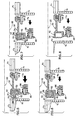
- FIG. 5 corresponds to FIG. 2, but shows the improved, double stepped shrouded seal in an undeteriorated or normally deteriorated condition. As is evident, the forces are substantially the same as those of FIG. 2, with the result that the seal is urged closed.
- FIG. 6 shows the improved, double stepped shrouded seal in a highly deteriorated condition similar to the condition of the conventional seal in FIG. 3.
- the blank of the carbon ring of FIG. 6 includes the first radial region 58 and its associated step 61 extending axially beyond the second radial region 60 and its associated step 63.
- the seal of FIG. 5 includes the shroud 42 on the seal housing.
- the axially extended first region 58 throttles the high pressure across a radial transition region that is radially narrower than the transition region of FIG. 3. Accordingly, the aggregate force F o of FIG. 6 is less than the aggregate force F o of FIG. 3.
- the carbon ring 52 of FIG. 6 is less likely to separate from the seal seat 24 than is the carbon ring of FIG. 3.
- FIG. 7 shows the improved, shrouded seal in a more severely deteriorated condition.
- FIG. 7 shows the carbon ring 52 worn back essentially to the shroud 42 and therefore shows a throttling effect attributable to the shroud.
- the shroud and the axially extended first region 58 of the carbon ring throttle the high pressure across a radial transition region that is radially narrower than the transition region of FIG. 3. Accordingly, the force magnitude F o of FIG. 7 is less than the force magnitude F o of FIG. 3.
- the carbon ring of FIG. 7 is less likely than the carbon ring of FIG. 3 to separate from the seal seat 24 and permit leakage.
- the shroud tip will eventually contact the seal seat 24 resulting in a more pronounced throttling effect.
- FIG. 8 shows the improved, shrouded seal in a damaged condition in which the carbon ring has been broken away over all or part of its circumference.
- the shroud 42 contacts the seal element and throttles the high pressure across a radially narrow transition so that the seal remains closed and resists leakage.
- the improved, shrouded seal deteriorates more gradually than a conventional unshrouded seal.
- the gradual deterioration is desirable because it manifests itself as noticeable but minor anomalies in engine performance. These minor anomalies make the engine operator aware that seal replacement or repair is required. Such replacement or repair may then be effected before the seal deteriorates enough to cause more significant problems.
- FIG. 9 shows a seal like that of FIGS. 1 and 5-8 in which the housing 32 is made of a selected material.
- the shroud has a tip 74 at its axial extremity remote from the housing base 34.
- the tip is made of the same material as the rest of the housing.
- FIG. 10 shows a seal in which the housing 32 is made of a parent material and the shroud has a tip 74 which is a region of the shroud impregnated with a second material.
- the shroud tip may be a feature made of or impregnated with a second material and bonded to the rest of the shroud or may be a coating.
- the second material may be any material having characteristics that are desirable when the tip contacts the seal seat 24. These include materials more lubricious than the parent material, materials harder than the parent material and materials more abradable than the parent material.
- FIGS. 11-13 show a seal in which the shroud comprises a stem 76 and a tip in the form of an insert or attachment 78 affixed to the stem.
- the insert is affixed with a radially outer snap 82.
- the insert is affixed with a radially inner snap 84.
- the insert is a molded tip secured to the stem 76 through a set of circumferentially distributed countersunk holes 86.
- the tip insert may be made of a material having characteristics that are desirable when the tip contacts the seal ring 24 . These include materials more lubricious than the parent material, materials harder than the parent material and materials more abradable than the parent material.
Landscapes
- Engineering & Computer Science (AREA)
- General Engineering & Computer Science (AREA)
- Mechanical Engineering (AREA)
- Turbine Rotor Nozzle Sealing (AREA)
- Mechanical Sealing (AREA)
- Sealing Of Bearings (AREA)
Priority Applications (1)
| Application Number | Priority Date | Filing Date | Title |
|---|---|---|---|
| EP13184397.1A EP2674578A1 (fr) | 2005-11-03 | 2006-11-03 | Élément d'étanchéité |
Applications Claiming Priority (1)
| Application Number | Priority Date | Filing Date | Title |
|---|---|---|---|
| US11/266,454 US7837199B2 (en) | 2005-11-03 | 2005-11-03 | Shrouded face seal and components thereof |
Publications (3)
| Publication Number | Publication Date |
|---|---|
| EP1783329A2 true EP1783329A2 (fr) | 2007-05-09 |
| EP1783329A3 EP1783329A3 (fr) | 2010-08-04 |
| EP1783329B1 EP1783329B1 (fr) | 2013-09-18 |
Family
ID=37885923
Family Applications (2)
| Application Number | Title | Priority Date | Filing Date |
|---|---|---|---|
| EP13184397.1A Withdrawn EP2674578A1 (fr) | 2005-11-03 | 2006-11-03 | Élément d'étanchéité |
| EP20060255681 Active EP1783329B1 (fr) | 2005-11-03 | 2006-11-03 | Garniture d'étanchéité carénée |
Family Applications Before (1)
| Application Number | Title | Priority Date | Filing Date |
|---|---|---|---|
| EP13184397.1A Withdrawn EP2674578A1 (fr) | 2005-11-03 | 2006-11-03 | Élément d'étanchéité |
Country Status (4)
| Country | Link |
|---|---|
| US (4) | US7837199B2 (fr) |
| EP (2) | EP2674578A1 (fr) |
| JP (1) | JP2007127276A (fr) |
| CA (1) | CA2562434A1 (fr) |
Cited By (4)
| Publication number | Priority date | Publication date | Assignee | Title |
|---|---|---|---|---|
| EP2058565A1 (fr) * | 2007-11-08 | 2009-05-13 | Schunk Kohlenstofftechnik GmbH | Elément d'étanchéité dynamique |
| EP2060742A2 (fr) | 2007-11-13 | 2009-05-20 | United Technologies Corporation | Ensemble de joint à double configuration pour ensemble rotatif |
| EP2570612A1 (fr) * | 2011-09-15 | 2013-03-20 | United Technologies Corporation | Assemblage de joints secondaires de turbomachine |
| EP3118418A1 (fr) * | 2015-07-15 | 2017-01-18 | United Technologies Corporation | Patin de joint avec régulation de la lubrification par huile |
Families Citing this family (34)
| Publication number | Priority date | Publication date | Assignee | Title |
|---|---|---|---|---|
| EP2088327B1 (fr) * | 2008-02-11 | 2011-08-31 | Agilent Technologies Italia S.p.A. | Support de roulement à rouleaux |
| US20100109250A1 (en) * | 2008-11-04 | 2010-05-06 | Werner Hueck | Dynamic sealing element |
| IT1400729B1 (it) * | 2010-07-08 | 2013-07-02 | Turboden Srl | Dispositivo di tenuta di fluido per macchine rotanti. |
| US8915421B2 (en) * | 2010-08-13 | 2014-12-23 | Lear Sirous Lavi | Transfer, link, bind, specimen tube barcode information to RFID specimen transport puck in a continuous moving binding process method |
| FR2989116B1 (fr) * | 2012-04-05 | 2014-04-25 | Snecma | Dispositif d'etancheite inter-arbres coaxiaux d'une turbomachine |
| CN108240335B (zh) * | 2012-07-23 | 2019-09-20 | 艾默生环境优化技术有限公司 | 用于压缩机的注入模制密封件 |
| US9605677B2 (en) | 2012-07-23 | 2017-03-28 | Emerson Climate Technologies, Inc. | Anti-wear coatings for scroll compressor wear surfaces |
| US9683451B2 (en) | 2013-01-04 | 2017-06-20 | United Technologies Corporation | Seal assembly for arranging between a stator and a rotor |
| US9156310B2 (en) * | 2013-01-11 | 2015-10-13 | Siemens Industry, Inc | Controlled lubricant volume seal housing |
| US10024241B2 (en) | 2013-03-15 | 2018-07-17 | United Technologies Corporation | Turbine engine face seal arrangement including anti-rotation features |
| EP3060782B1 (fr) | 2013-10-22 | 2019-04-03 | United Technologies Corporation | Agencement de garniture mécanique avec plaque de retenue |
| EP3066368B1 (fr) | 2013-11-06 | 2019-04-17 | United Technologies Corporation | Plaque d'étanchéité à cuillère axiale |
| US9587501B2 (en) * | 2013-11-11 | 2017-03-07 | General Electric Company | Rotary machine secondary sealing assembly and method of assembling the same |
| US10030528B2 (en) | 2014-01-08 | 2018-07-24 | United Technologies Corporation | Flanged spring guide for a face seal arrangement |
| US9395000B2 (en) * | 2014-08-19 | 2016-07-19 | Flowserve Management Company | Apparatus for excluding particle contaminants from a gas lift off mechanical seal |
| ES2922769T3 (es) * | 2015-06-26 | 2022-09-20 | Danfoss As | Máquina hidráulica |
| US10125625B2 (en) * | 2015-08-03 | 2018-11-13 | Siemens Energy, Inc. | Gas turbine engine component with performance feature |
| US10563530B2 (en) * | 2015-10-12 | 2020-02-18 | General Electric Company | Intershaft seal with dual opposing carbon seal rings |
| US10012315B2 (en) | 2016-05-23 | 2018-07-03 | United Technologies Corporation | Seal assembly |
| GB2553565B (en) * | 2016-09-09 | 2019-04-10 | Rolls Royce Plc | Air riding seal arrangement |
| US10788131B2 (en) * | 2017-08-01 | 2020-09-29 | Raytheon Technologies Corporation | Face seal arrangement |
| US10619741B2 (en) | 2017-09-12 | 2020-04-14 | United Technologies Corporation | Contacting dry face seal with tapered carbon nose |
| US20190178381A1 (en) * | 2017-12-13 | 2019-06-13 | United Technologies Corporation | Face seal arrangement with air load force balance recovery for improved failure mitigation strategies |
| US10669877B2 (en) * | 2017-12-21 | 2020-06-02 | United Technologies Corporation | Air seal attachment |
| US10851664B2 (en) | 2018-08-02 | 2020-12-01 | Pratt & Whitney Canada Corp. | Sealing assembly for a gas turbine engine |
| US11193384B2 (en) * | 2018-09-19 | 2021-12-07 | Raytheon Technologies Corporation | Low friction, wear resistant dry face carbon seal—seal seat assembly |
| US11719114B2 (en) * | 2018-09-19 | 2023-08-08 | Raytheon Technologies Corporation | Low friction carbon—carbon seal assembly |
| US11035253B2 (en) * | 2019-02-05 | 2021-06-15 | Raytheon Technologies Corporation | Face seal with damper |
| US11313471B2 (en) | 2020-05-05 | 2022-04-26 | Raytheon Technologies Corporation | Shrouded aircraft engine seal carrier |
| US11454324B2 (en) * | 2020-08-26 | 2022-09-27 | Raytheon Technologies Corporation | Face seal carrier arrester |
| US11401832B2 (en) * | 2021-01-05 | 2022-08-02 | Raytheon Technologies Corporation | Gas turbine engine including seal plate with separable tabs |
| US11608751B2 (en) * | 2021-03-19 | 2023-03-21 | Raytheon Technologies Corporation | Self-guiding carbon seal system |
| US12060798B2 (en) | 2022-05-27 | 2024-08-13 | General Electric Company | Surface treatment for seal assemblies |
| US11891898B2 (en) * | 2022-06-10 | 2024-02-06 | General Electric Company | Seal assemblies for turbine engines |
Family Cites Families (29)
| Publication number | Priority date | Publication date | Assignee | Title |
|---|---|---|---|---|
| US2554406A (en) * | 1946-12-13 | 1951-05-22 | Crane Packing Co | Rotary fluid seal with "o" ring |
| US2592728A (en) * | 1948-12-04 | 1952-04-15 | Crane Packing Co | Rotary mechanical seal |
| US2882076A (en) * | 1956-08-23 | 1959-04-14 | City Nat Bank And Trust Compan | Rotary seal |
| US3024048A (en) * | 1960-01-29 | 1962-03-06 | Microtite Corp | Shaft seal |
| US3356377A (en) * | 1965-08-13 | 1967-12-05 | Continental Illinois Nat Bank | Fluid sealing assembly with resilient sealing rings |
| US3536333A (en) * | 1968-03-18 | 1970-10-27 | Pac Seal Inc | Rotary seals |
| US3841642A (en) * | 1971-05-28 | 1974-10-15 | Sealol | Rotary mechanical fluid seal |
| US3784213A (en) * | 1972-06-20 | 1974-01-08 | Innovatex Corp | Rotary face seal assembly |
| DE2545917A1 (de) * | 1974-10-17 | 1976-04-29 | Fenner Co Ltd J H | Wellendichtung |
| JPS5810616B2 (ja) * | 1979-04-04 | 1983-02-26 | 株式会社日立製作所 | メカニカルシ−ル |
| US4600318A (en) * | 1985-08-01 | 1986-07-15 | Sundstrand Corporation | Thrust bearing and seal assembly |
| US4715260A (en) * | 1986-12-22 | 1987-12-29 | General Electric Company | Seal |
| US4768790A (en) * | 1987-05-22 | 1988-09-06 | John Crane-Houdaille, Inc. | Mechanical face seal having centering means |
| US4997191A (en) * | 1989-10-17 | 1991-03-05 | Gits Bros. Mfg. Co. | Adjustable shaft seal and method of adjustment |
| JP3555683B2 (ja) * | 1992-08-11 | 2004-08-18 | ユナイテッド・テクノロジーズ・コーポレイション | 回転機用シールアセンブリ |
| BE1008503A3 (nl) * | 1994-07-18 | 1996-05-07 | Agfa Gevaert Nv | Initiatie van de delaminatie van een droog verwerkbaar beeld. |
| US6213472B1 (en) * | 1994-11-16 | 2001-04-10 | Dresser-Rand Company | Shaft seal |
| US5567132A (en) * | 1994-12-06 | 1996-10-22 | Endura Pumps International, Inc. | Seal for pump having an internal gas pump |
| US5658127A (en) * | 1996-01-26 | 1997-08-19 | Sundstrand Corporation | Seal element cooling in high speed mechanical face seals |
| JP3650954B2 (ja) * | 1998-09-18 | 2005-05-25 | イーグル工業株式会社 | 高速用非接触型メカニカルシール |
| US6196790B1 (en) * | 1998-12-17 | 2001-03-06 | United Technologies Corporation | Seal assembly for an intershaft seal in a gas turbine engine |
| US6132168A (en) | 1998-12-23 | 2000-10-17 | United Technologies Corporation | Balancing a pressure drop across ring seals in gas turbine engines |
| DE29908918U1 (de) * | 1999-05-20 | 1999-07-29 | Feodor Burgmann Dichtungswerke GmbH & Co, 82515 Wolfratshausen | Gleitringdichtungsanordnung |
| CA2382996C (fr) * | 1999-07-27 | 2008-12-02 | Northeast Equipment, Inc. D/B/A Delta Mechanical Seals | Joint fendu mecanique |
| US6494458B2 (en) * | 2000-12-19 | 2002-12-17 | Karl E. Uth | Rotary sealing assembly |
| US6679678B2 (en) * | 2002-05-31 | 2004-01-20 | Honeywell International, Inc. | Increased wear-life mechanical face seal anti-rotation system |
| US20040026868A1 (en) * | 2002-08-02 | 2004-02-12 | Dahlheimer John C. | Face seal with secondary seal |
| JP4481690B2 (ja) * | 2004-03-19 | 2010-06-16 | イーグル工業株式会社 | メカニカルシール装置 |
| US7377518B2 (en) * | 2004-05-28 | 2008-05-27 | John Crane Inc. | Mechanical seal ring assembly with hydrodynamic pumping mechanism |
-
2005
- 2005-11-03 US US11/266,454 patent/US7837199B2/en not_active Expired - Lifetime
-
2006
- 2006-10-03 CA CA 2562434 patent/CA2562434A1/fr not_active Abandoned
- 2006-10-27 JP JP2006291909A patent/JP2007127276A/ja active Pending
- 2006-11-03 EP EP13184397.1A patent/EP2674578A1/fr not_active Withdrawn
- 2006-11-03 EP EP20060255681 patent/EP1783329B1/fr active Active
-
2010
- 2010-06-29 US US12/826,629 patent/US9004492B2/en active Active
-
2015
- 2015-03-23 US US14/665,068 patent/US9194499B2/en not_active Expired - Lifetime
- 2015-09-11 US US14/851,679 patent/US9239117B1/en not_active Expired - Lifetime
Non-Patent Citations (1)
| Title |
|---|
| None |
Cited By (6)
| Publication number | Priority date | Publication date | Assignee | Title |
|---|---|---|---|---|
| EP2058565A1 (fr) * | 2007-11-08 | 2009-05-13 | Schunk Kohlenstofftechnik GmbH | Elément d'étanchéité dynamique |
| EP2060742A2 (fr) | 2007-11-13 | 2009-05-20 | United Technologies Corporation | Ensemble de joint à double configuration pour ensemble rotatif |
| EP2060742A3 (fr) * | 2007-11-13 | 2013-03-20 | United Technologies Corporation | Ensemble de joint à double configuration pour ensemble rotatif |
| EP2570612A1 (fr) * | 2011-09-15 | 2013-03-20 | United Technologies Corporation | Assemblage de joints secondaires de turbomachine |
| US9316119B2 (en) | 2011-09-15 | 2016-04-19 | United Technologies Corporation | Turbomachine secondary seal assembly |
| EP3118418A1 (fr) * | 2015-07-15 | 2017-01-18 | United Technologies Corporation | Patin de joint avec régulation de la lubrification par huile |
Also Published As
| Publication number | Publication date |
|---|---|
| US9194499B2 (en) | 2015-11-24 |
| US9004492B2 (en) | 2015-04-14 |
| US9239117B1 (en) | 2016-01-19 |
| CA2562434A1 (fr) | 2007-05-03 |
| US7837199B2 (en) | 2010-11-23 |
| US20150198253A1 (en) | 2015-07-16 |
| EP1783329A3 (fr) | 2010-08-04 |
| US20070108704A1 (en) | 2007-05-17 |
| US20150377361A1 (en) | 2015-12-31 |
| EP1783329B1 (fr) | 2013-09-18 |
| US20100264601A1 (en) | 2010-10-21 |
| JP2007127276A (ja) | 2007-05-24 |
| EP2674578A1 (fr) | 2013-12-18 |
Similar Documents
| Publication | Publication Date | Title |
|---|---|---|
| US9194499B2 (en) | Shrouded face seal and components thereof | |
| US11028927B2 (en) | Wide differential pressure range air riding carbon seal | |
| US5244215A (en) | Rotary shaft seal with retractable excluder lip | |
| US7984911B2 (en) | Face seal for gas turbine engine | |
| US8109716B2 (en) | Gas turbine engine systems involving hydrostatic face seals with anti-fouling provisioning | |
| US6142729A (en) | Sealing device for a turbomachine bearing chamber | |
| EP1777376A2 (fr) | Joint d'étanchéité inter-arbres tandem en graphite | |
| EP1963622B1 (fr) | Joint d'étanchéité à brosse flottant et auto-centrant, ensemble et procédé de modernisation associés | |
| EP1577504B1 (fr) | Joint d'étanchéité pour palier muni d'un dispositif de sécurité | |
| US11085540B2 (en) | Circumferential air riding carbon seal on ceramic runner | |
| KR101355715B1 (ko) | 특히 휠 허브용 환상 밀봉 조립체 | |
| US11255436B2 (en) | Circumferential archbound carbon seal on ceramic runner | |
| US10215289B2 (en) | High temperature shaft seal for bleed valve with roller bearings | |
| US11287043B2 (en) | High clearance seal assembly | |
| US9097347B2 (en) | Carbon seal assembly | |
| JP2002122243A (ja) | 分割型シール | |
| CN115095429B (zh) | 一种用于航空发动机转子间滑油腔密封的石墨密封结构 | |
| US20020041070A1 (en) | Contactless axial carbon seal for a bearing chamber | |
| CN114321389A (zh) | 平衡型涨圈密封装置 | |
| JP2010025137A (ja) | 回転用オイルシール | |
| EP0995917A2 (fr) | Dispositif d'étanchéité pour deux éléments mécaniques connectés en rotation relative, particulièrement pour deux bagues d'un palier à roulement | |
| CN218407614U (zh) | 涡喷发动机及其封严结构 | |
| JPH075324Y2 (ja) | シャットダウンシール機構を備えたメカニカルシール | |
| CA3105202A1 (fr) | Ensemble rotor et logement de rotor d'un moteur a turbine | |
| JP2006046549A (ja) | 密封装置 |
Legal Events
| Date | Code | Title | Description |
|---|---|---|---|
| PUAI | Public reference made under article 153(3) epc to a published international application that has entered the european phase |
Free format text: ORIGINAL CODE: 0009012 |
|
| AK | Designated contracting states |
Kind code of ref document: A2 Designated state(s): AT BE BG CH CY CZ DE DK EE ES FI FR GB GR HU IE IS IT LI LT LU LV MC NL PL PT RO SE SI SK TR |
|
| AX | Request for extension of the european patent |
Extension state: AL BA HR MK YU |
|
| PUAL | Search report despatched |
Free format text: ORIGINAL CODE: 0009013 |
|
| AK | Designated contracting states |
Kind code of ref document: A3 Designated state(s): AT BE BG CH CY CZ DE DK EE ES FI FR GB GR HU IE IS IT LI LT LU LV MC NL PL PT RO SE SI SK TR |
|
| AX | Request for extension of the european patent |
Extension state: AL BA HR MK RS |
|
| 17P | Request for examination filed |
Effective date: 20110203 |
|
| AKX | Designation fees paid |
Designated state(s): DE GB |
|
| GRAP | Despatch of communication of intention to grant a patent |
Free format text: ORIGINAL CODE: EPIDOSNIGR1 |
|
| GRAP | Despatch of communication of intention to grant a patent |
Free format text: ORIGINAL CODE: EPIDOSNIGR1 |
|
| INTG | Intention to grant announced |
Effective date: 20130328 |
|
| GRAS | Grant fee paid |
Free format text: ORIGINAL CODE: EPIDOSNIGR3 |
|
| GRAA | (expected) grant |
Free format text: ORIGINAL CODE: 0009210 |
|
| AK | Designated contracting states |
Kind code of ref document: B1 Designated state(s): DE GB |
|
| REG | Reference to a national code |
Ref country code: GB Ref legal event code: FG4D |
|
| REG | Reference to a national code |
Ref country code: DE Ref legal event code: R081 Ref document number: 602006038449 Country of ref document: DE Owner name: UNITED TECHNOLOGIES CORP. (N.D.GES.D. STAATES , US Free format text: FORMER OWNER: UNITED TECHNOLOGIES CORP. (N.D.GES.D. STAATES DELAWARE), HARTFORD, CONN., US |
|
| REG | Reference to a national code |
Ref country code: DE Ref legal event code: R096 Ref document number: 602006038449 Country of ref document: DE Effective date: 20131114 |
|
| REG | Reference to a national code |
Ref country code: DE Ref legal event code: R097 Ref document number: 602006038449 Country of ref document: DE |
|
| PLBE | No opposition filed within time limit |
Free format text: ORIGINAL CODE: 0009261 |
|
| STAA | Information on the status of an ep patent application or granted ep patent |
Free format text: STATUS: NO OPPOSITION FILED WITHIN TIME LIMIT |
|
| 26N | No opposition filed |
Effective date: 20140619 |
|
| REG | Reference to a national code |
Ref country code: DE Ref legal event code: R097 Ref document number: 602006038449 Country of ref document: DE Effective date: 20140619 |
|
| REG | Reference to a national code |
Ref country code: DE Ref legal event code: R082 Ref document number: 602006038449 Country of ref document: DE Representative=s name: SCHMITT-NILSON SCHRAUD WAIBEL WOHLFROM PATENTA, DE |
|
| REG | Reference to a national code |
Ref country code: DE Ref legal event code: R082 Ref document number: 602006038449 Country of ref document: DE Representative=s name: SCHMITT-NILSON SCHRAUD WAIBEL WOHLFROM PATENTA, DE Ref country code: DE Ref legal event code: R081 Ref document number: 602006038449 Country of ref document: DE Owner name: UNITED TECHNOLOGIES CORP. (N.D.GES.D. STAATES , US Free format text: FORMER OWNER: UNITED TECHNOLOGIES CORPORATION, HARTFORD, CONN., US |
|
| PGFP | Annual fee paid to national office [announced via postgrant information from national office to epo] |
Ref country code: DE Payment date: 20191021 Year of fee payment: 14 |
|
| REG | Reference to a national code |
Ref country code: DE Ref legal event code: R119 Ref document number: 602006038449 Country of ref document: DE |
|
| PG25 | Lapsed in a contracting state [announced via postgrant information from national office to epo] |
Ref country code: DE Free format text: LAPSE BECAUSE OF NON-PAYMENT OF DUE FEES Effective date: 20210601 |
|
| PGFP | Annual fee paid to national office [announced via postgrant information from national office to epo] |
Ref country code: GB Payment date: 20251023 Year of fee payment: 20 |