EP1783336A1 - Système de traitement des gaz d'échappement d'un véhicule - Google Patents
Système de traitement des gaz d'échappement d'un véhicule Download PDFInfo
- Publication number
- EP1783336A1 EP1783336A1 EP06076922A EP06076922A EP1783336A1 EP 1783336 A1 EP1783336 A1 EP 1783336A1 EP 06076922 A EP06076922 A EP 06076922A EP 06076922 A EP06076922 A EP 06076922A EP 1783336 A1 EP1783336 A1 EP 1783336A1
- Authority
- EP
- European Patent Office
- Prior art keywords
- exhaust
- treatment system
- adsorber
- vehicle exhaust
- volume
- Prior art date
- Legal status (The legal status is an assumption and is not a legal conclusion. Google has not performed a legal analysis and makes no representation as to the accuracy of the status listed.)
- Withdrawn
Links
Images

Classifications
-
- F—MECHANICAL ENGINEERING; LIGHTING; HEATING; WEAPONS; BLASTING
- F01—MACHINES OR ENGINES IN GENERAL; ENGINE PLANTS IN GENERAL; STEAM ENGINES
- F01N—GAS-FLOW SILENCERS OR EXHAUST APPARATUS FOR MACHINES OR ENGINES IN GENERAL; GAS-FLOW SILENCERS OR EXHAUST APPARATUS FOR INTERNAL-COMBUSTION ENGINES
- F01N3/00—Exhaust or silencing apparatus having means for purifying, rendering innocuous, or otherwise treating exhaust
- F01N3/02—Exhaust or silencing apparatus having means for purifying, rendering innocuous, or otherwise treating exhaust for cooling, or for removing solid constituents of, exhaust
- F01N3/021—Exhaust or silencing apparatus having means for purifying, rendering innocuous, or otherwise treating exhaust for cooling, or for removing solid constituents of, exhaust by means of filters
- F01N3/023—Exhaust or silencing apparatus having means for purifying, rendering innocuous, or otherwise treating exhaust for cooling, or for removing solid constituents of, exhaust by means of filters using means for regenerating the filters, e.g. by burning trapped particles
- F01N3/025—Exhaust or silencing apparatus having means for purifying, rendering innocuous, or otherwise treating exhaust for cooling, or for removing solid constituents of, exhaust by means of filters using means for regenerating the filters, e.g. by burning trapped particles using fuel burner or by adding fuel to exhaust
-
- F—MECHANICAL ENGINEERING; LIGHTING; HEATING; WEAPONS; BLASTING
- F01—MACHINES OR ENGINES IN GENERAL; ENGINE PLANTS IN GENERAL; STEAM ENGINES
- F01N—GAS-FLOW SILENCERS OR EXHAUST APPARATUS FOR MACHINES OR ENGINES IN GENERAL; GAS-FLOW SILENCERS OR EXHAUST APPARATUS FOR INTERNAL-COMBUSTION ENGINES
- F01N13/00—Exhaust or silencing apparatus characterised by constructional features
- F01N13/009—Exhaust or silencing apparatus characterised by constructional features having two or more separate purifying devices arranged in series
-
- F—MECHANICAL ENGINEERING; LIGHTING; HEATING; WEAPONS; BLASTING
- F01—MACHINES OR ENGINES IN GENERAL; ENGINE PLANTS IN GENERAL; STEAM ENGINES
- F01N—GAS-FLOW SILENCERS OR EXHAUST APPARATUS FOR MACHINES OR ENGINES IN GENERAL; GAS-FLOW SILENCERS OR EXHAUST APPARATUS FOR INTERNAL-COMBUSTION ENGINES
- F01N13/00—Exhaust or silencing apparatus characterised by constructional features
- F01N13/009—Exhaust or silencing apparatus characterised by constructional features having two or more separate purifying devices arranged in series
- F01N13/0093—Exhaust or silencing apparatus characterised by constructional features having two or more separate purifying devices arranged in series the purifying devices are of the same type
-
- F—MECHANICAL ENGINEERING; LIGHTING; HEATING; WEAPONS; BLASTING
- F01—MACHINES OR ENGINES IN GENERAL; ENGINE PLANTS IN GENERAL; STEAM ENGINES
- F01N—GAS-FLOW SILENCERS OR EXHAUST APPARATUS FOR MACHINES OR ENGINES IN GENERAL; GAS-FLOW SILENCERS OR EXHAUST APPARATUS FOR INTERNAL-COMBUSTION ENGINES
- F01N13/00—Exhaust or silencing apparatus characterised by constructional features
- F01N13/009—Exhaust or silencing apparatus characterised by constructional features having two or more separate purifying devices arranged in series
- F01N13/0097—Exhaust or silencing apparatus characterised by constructional features having two or more separate purifying devices arranged in series the purifying devices are arranged in a single housing
-
- F—MECHANICAL ENGINEERING; LIGHTING; HEATING; WEAPONS; BLASTING
- F01—MACHINES OR ENGINES IN GENERAL; ENGINE PLANTS IN GENERAL; STEAM ENGINES
- F01N—GAS-FLOW SILENCERS OR EXHAUST APPARATUS FOR MACHINES OR ENGINES IN GENERAL; GAS-FLOW SILENCERS OR EXHAUST APPARATUS FOR INTERNAL-COMBUSTION ENGINES
- F01N3/00—Exhaust or silencing apparatus having means for purifying, rendering innocuous, or otherwise treating exhaust
- F01N3/08—Exhaust or silencing apparatus having means for purifying, rendering innocuous, or otherwise treating exhaust for rendering innocuous
- F01N3/0807—Exhaust or silencing apparatus having means for purifying, rendering innocuous, or otherwise treating exhaust for rendering innocuous by using absorbents or adsorbents
- F01N3/0814—Exhaust or silencing apparatus having means for purifying, rendering innocuous, or otherwise treating exhaust for rendering innocuous by using absorbents or adsorbents combined with catalytic converters, e.g. NOx absorption/storage reduction catalysts
-
- F—MECHANICAL ENGINEERING; LIGHTING; HEATING; WEAPONS; BLASTING
- F01—MACHINES OR ENGINES IN GENERAL; ENGINE PLANTS IN GENERAL; STEAM ENGINES
- F01N—GAS-FLOW SILENCERS OR EXHAUST APPARATUS FOR MACHINES OR ENGINES IN GENERAL; GAS-FLOW SILENCERS OR EXHAUST APPARATUS FOR INTERNAL-COMBUSTION ENGINES
- F01N3/00—Exhaust or silencing apparatus having means for purifying, rendering innocuous, or otherwise treating exhaust
- F01N3/08—Exhaust or silencing apparatus having means for purifying, rendering innocuous, or otherwise treating exhaust for rendering innocuous
- F01N3/0807—Exhaust or silencing apparatus having means for purifying, rendering innocuous, or otherwise treating exhaust for rendering innocuous by using absorbents or adsorbents
- F01N3/0828—Exhaust or silencing apparatus having means for purifying, rendering innocuous, or otherwise treating exhaust for rendering innocuous by using absorbents or adsorbents characterised by the absorbed or adsorbed substances
- F01N3/0842—Nitrogen oxides
-
- F—MECHANICAL ENGINEERING; LIGHTING; HEATING; WEAPONS; BLASTING
- F01—MACHINES OR ENGINES IN GENERAL; ENGINE PLANTS IN GENERAL; STEAM ENGINES
- F01N—GAS-FLOW SILENCERS OR EXHAUST APPARATUS FOR MACHINES OR ENGINES IN GENERAL; GAS-FLOW SILENCERS OR EXHAUST APPARATUS FOR INTERNAL-COMBUSTION ENGINES
- F01N3/00—Exhaust or silencing apparatus having means for purifying, rendering innocuous, or otherwise treating exhaust
- F01N3/08—Exhaust or silencing apparatus having means for purifying, rendering innocuous, or otherwise treating exhaust for rendering innocuous
- F01N3/10—Exhaust or silencing apparatus having means for purifying, rendering innocuous, or otherwise treating exhaust for rendering innocuous by thermal or catalytic conversion of noxious components of exhaust
- F01N3/18—Exhaust or silencing apparatus having means for purifying, rendering innocuous, or otherwise treating exhaust for rendering innocuous by thermal or catalytic conversion of noxious components of exhaust characterised by methods of operation; Control
- F01N3/20—Exhaust or silencing apparatus having means for purifying, rendering innocuous, or otherwise treating exhaust for rendering innocuous by thermal or catalytic conversion of noxious components of exhaust characterised by methods of operation; Control specially adapted for catalytic conversion
- F01N3/2006—Periodically heating or cooling catalytic reactors, e.g. at cold starting or overheating
-
- F—MECHANICAL ENGINEERING; LIGHTING; HEATING; WEAPONS; BLASTING
- F01—MACHINES OR ENGINES IN GENERAL; ENGINE PLANTS IN GENERAL; STEAM ENGINES
- F01N—GAS-FLOW SILENCERS OR EXHAUST APPARATUS FOR MACHINES OR ENGINES IN GENERAL; GAS-FLOW SILENCERS OR EXHAUST APPARATUS FOR INTERNAL-COMBUSTION ENGINES
- F01N2240/00—Combination or association of two or more different exhaust treating devices, or of at least one such device with an auxiliary device, not covered by indexing codes F01N2230/00 or F01N2250/00, one of the devices being
- F01N2240/30—Combination or association of two or more different exhaust treating devices, or of at least one such device with an auxiliary device, not covered by indexing codes F01N2230/00 or F01N2250/00, one of the devices being a fuel reformer
-
- Y—GENERAL TAGGING OF NEW TECHNOLOGICAL DEVELOPMENTS; GENERAL TAGGING OF CROSS-SECTIONAL TECHNOLOGIES SPANNING OVER SEVERAL SECTIONS OF THE IPC; TECHNICAL SUBJECTS COVERED BY FORMER USPC CROSS-REFERENCE ART COLLECTIONS [XRACs] AND DIGESTS
- Y02—TECHNOLOGIES OR APPLICATIONS FOR MITIGATION OR ADAPTATION AGAINST CLIMATE CHANGE
- Y02A—TECHNOLOGIES FOR ADAPTATION TO CLIMATE CHANGE
- Y02A50/00—TECHNOLOGIES FOR ADAPTATION TO CLIMATE CHANGE in human health protection, e.g. against extreme weather
- Y02A50/20—Air quality improvement or preservation, e.g. vehicle emission control or emission reduction by using catalytic converters
-
- Y—GENERAL TAGGING OF NEW TECHNOLOGICAL DEVELOPMENTS; GENERAL TAGGING OF CROSS-SECTIONAL TECHNOLOGIES SPANNING OVER SEVERAL SECTIONS OF THE IPC; TECHNICAL SUBJECTS COVERED BY FORMER USPC CROSS-REFERENCE ART COLLECTIONS [XRACs] AND DIGESTS
- Y02—TECHNOLOGIES OR APPLICATIONS FOR MITIGATION OR ADAPTATION AGAINST CLIMATE CHANGE
- Y02T—CLIMATE CHANGE MITIGATION TECHNOLOGIES RELATED TO TRANSPORTATION
- Y02T10/00—Road transport of goods or passengers
- Y02T10/10—Internal combustion engine [ICE] based vehicles
- Y02T10/12—Improving ICE efficiencies
Definitions
- the present invention relates to a vehicle exhaust after treatment system, more particularly, to an after treatment system architecture for reducing cold start emissions.
- the quantities of pollutants generated by incomplete combustion varies with operating conditions of the engine but are influenced predominantly by the air-to-fuel ratio in the combustion cylinder.
- Conditions conducive to reducing carbon monoxide and unburned hydrocarbons i.e., a fuel mixture just lean of stoichiometric and high combustion temperatures, cause an increased formation of NO x
- conditions conducive to reducing the formation of NO x i.e., rich fuel mixture and low combustion temperatures, cause an increase in carbon monoxide and unburned hydrocarbons in the exhaust gases.
- significant amounts of CO, HC and NO x are emitted from the engine.
- the catalyst can be heated to light-off temperature, using, for example, exhaust heating, injection of reformate, and heating of reformate using an in-exhaust burner.
- Reformates are hydrogen-enriched fuels that can be produced from a variety of sources, including gasoline, diesel, and other liquid or gaseous fuels.
- On-board reformers for producing hydrogen-enriched reformate fuels are described in, for example, U.S. Patent Nos. 6,655,130 and 6,832,473 and U.S. Patent Appl. Publ. Nos. 2004/0146458 and 2005/0022450 , the disclosures of which are incorporated herein by reference.
- the vehicle exhaust after treatment system of the present invention which is particularly suitable for use with a diesel engine, includes an exhaust catalyst that comprises a small volume NO x adsorber coupled with a small volume oxidation catalyst.
- This configuration of the exhaust catalyst enables it to be quickly heated to the temperature where NO x storage begins to occur, typically above 150°C, and then to light-off temperature, where the catalyst is able to convert the stored NO x to N 2 . This rapid storage and light-off also allows the amount of included precious metal to be reduced.
- the present invention is directed to a vehicle exhaust after treatment system for controlling emissions from an engine.
- the system comprises, in serial order: an exhaust outlet from the engine, an exhaust catalyst assembly that is in fluid communication with the exhaust outlet and comprises a first NO x adsorber coupled with a downstream oxidation catalyst, and a second NO x adsorber that is downstream from and in fluid communication with the oxidation catalyst of the exhaust catalyst assembly.
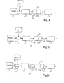
- FIGS. 1-6 indicate the direction of gas flow in the exhaust after treatment system of the present invention.
- a first embodiment 10 of the invention includes an exhaust outlet 11 connected to an exhaust catalyst assembly 12 comprising a first NO x component 12a coupled with a downstream oxidation catalyst 12b.
- An exhaust conduit 13 connects oxidation catalyst 12b with a second NO x adsorber 14, which preferably is an underfloor adsorber.
- System 10 preferably further includes a particulate filter 15 connected to second NO x adsorber 14 by exhaust conduit 13. The volume of particulate filter 15 preferably is greater than that of second NO x adsorber 14.
- Exhaust catalyst assembly 12 whose volume preferably is smaller than that of second NO x adsorber 14, can be rapidly brought to operating temperature by means of a heat source 16, preferably reformate fuel produced by an on-board reformer.
- the reformate fuel can be supplied to catalyst assembly 12 via a reformer conduit 17 connected to exhaust outlet 11.
- the volume of exhaust catalyst assembly 12 preferably is about 1.5 liters to about 3 liters, each of first NO x adsorber 12a and oxidation catalyst having a volume preferably of about 0.75 liter to about 1.5 liters.
- the volume of second NO x adsorber 14 preferably is about 5 liters to about 8 liters, and the volume of particulate filter 15 preferably is about 8 liters to about 13 liters.
- a second embodiment 20 of the invention is similar to that of system 10 schematically depicted in FIG. 1, except that a burner 21 is included in exhaust outlet 11 to increase the temperature of the reformate fuel delivered from heat source 16 and to oxidize any HC and CO that may be present, thereby preventing passage of these gases to downstream catalysts that have not yet reached their operating temperatures.
- a third embodiment 30 of the invention is similar to that of system 20 schematically depicted in FIG. 2, except that a second burner 31 is installed in exhaust conduit 13 downstream from second NO x adsorber 14. Burner 31 assists in the regeneration of particulate filter 15 by promoting the combustion of particles collected on the filter surfaces.
- a fourth embodiment 40 of the invention is similar to that of system 10 schematically depicted in FIG. 1, except that particulate filter 15 is connected to exhaust outlet 11 and is disposed upstream from catalyst assembly 12 comprising first NO x component 12a coupled with downstream oxidation catalyst 12b.
- exhaust conduit 13 connects oxidation catalyst 12b with second NO x adsorber 14, which preferably is an underfloor adsorber.
- System 40 further preferably includes heat source 16, preferably reformate fuel produced by an on-board reformer.
- the reformate fuel can be supplied to exhaust outlet 11 via reformer conduit 17.
- a fifth embodiment 50 of the invention is similar to that of system 40 schematically depicted in FIG. 4, except that a burner 21 is included in exhaust outlet 11 to increase the temperature of the reformate fuel delivered from heat source 16.
- a sixth embodiment 60 of the invention is similar to that of system 50 schematically depicted in FIG. 5, except that a second burner 31 is installed in exhaust conduit 13 downstream from particulate filter 15. Burner 31 assists in bringing catalyst assembly 12 comprising first NO x component 12a coupled with downstream oxidation catalyst 12b to its normal operating temperature.
- the NO x adsorbers 12a and 14 generally comprise a porous support, a catalytic metal component, and one or more NO x trapping materials.
- Suitable NO x trapping materials include alkali metals, alkaline earth metals, and the like, and combinations thereof.
- the catalytic metal component and NO x trapping materials can be washcoated, imbibed, impregnated, physisorbed, chemisorbed, precipitated, or otherwise applied onto and/or within the porous support.
- the porous support can comprise any material designed for use in a spark ignition or diesel engine environment.
- the porous support is selected to be capable of operating at temperatures up to about 1200°C and of withstanding exposure to hydrocarbons, nitrogen oxides, carbon monoxide, carbon dioxide, sulfur and/or sulfur oxides; furthermore it must have sufficient surface area and structural integrity to support the desired catalyst.
- Some possible materials include zirconium toughened alumina, cordierite, silicon carbide, metallic foils, alumina sponges, porous glasses, and the like, and mixtures thereof.
- the porous support can have any size or geometry, the size and geometry are preferably chosen to optimize surface area in the given design parameters.
- the catalytic metal components of NO x adsorbers 12a and 14 comprise precious metals such as, platinum, rhodium, palladium, ruthenium, iridium and osmium, as well as alloys and combinations thereof.
- the catalytic metal component is a combination of rhodium with one or more other metals
- the other metals e.g., palladium, platinum, and the like
- the porous support may be further loaded with one or more NO x trapping materials such as alkali metals, alkaline earth metal, and mixtures thereof. Suitable trapping materials include barium, lithium, potassium, magnesium, sodium, cesium, strontium, and combinations thereof.
- the oxidation catalyst 12b preferably comprises a catalytic metal including, but not limited to, platinum, palladium, ruthenium, rhodium, osmium, iridium, gold, silver, aluminum, gallium, indium, tin, and titanium, as well as oxides, alloys, salts, and mixtures thereof.
- catalyst 12b further includes a support that preferably comprises an inorganic oxide, preferably alumina, and zeolite in the proton form and having a high Si/Al ratio, as described in U.S. Patent No. 6,235,255 , the disclosure of which is incorporated herein by reference.
- the particulate filter 15 generally comprises a shell, an insulation material, and a filter element.
- the insulation material substantially covers the filter element, and the shell substantially covers the insulation material.
- Suitable materials for the shell include ferrous materials such as ferritic stainless steels.
- the insulation material comprises materials such as fiberglass, intumescent materials, non-intumescent materials, ceramic mats, and/or mica based materials, and combinations thereof.
- the porous filter element can include one or more monoliths, substrates, supports, and the like comprising, for example, ceramics, cermets, carbides, silicides, nitrides, and the like, and combinations thereof.
- the filter element also includes a metal catalyst such as platinum, palladium, rhodium, nickel, iron, cobalt, molybdenum, tungsten, vanadium, niobium, tantalum, their oxides and sulfides, and combinations thereof.
- the filter element can optionally include a washcoat material such as aluminum oxide, silicon oxide, zirconium oxide, titanium oxide, cerium oxide, and combinations thereof.
- Federal Test Procedure FTP-75 which is employed to measure light duty vehicle emissions, entails an operating cycle having a duration of 1874 seconds, divided into three phases, as follows:
- the FTP-75 test was carried out for a vehicle exhaust after treatment system of the present invention that includes, as depicted in FIG. 1, an exhaust catalyst assembly 12 comprising a first NO x adsorber 12a coupled with a downstream oxidation catalyst 12b, followed by a second NO x adsorber 14.
- the volume of exhaust catalyst assembly 12 was 2.5 liters, each of NO x component 12a and oxidation catalyst 12b having a volume of 1.25 liters.
- the volume of second NO x adsorber 14 was 5 liters.
- THC total hydrocarbons
- NMHC non-methane hydrocarbons
- CO carbon monoxide
- NO x nitrogen oxides
- the vehicle exhaust after treatment system of the present invention provides a substantial reduction in environment-damaging engine emissions.
- the benefit is especially striking in the large reductions in the amounts of emitted CO and NO x .
Landscapes
- Engineering & Computer Science (AREA)
- Chemical & Material Sciences (AREA)
- Combustion & Propulsion (AREA)
- Mechanical Engineering (AREA)
- General Engineering & Computer Science (AREA)
- Chemical Kinetics & Catalysis (AREA)
- Health & Medical Sciences (AREA)
- Toxicology (AREA)
- Exhaust Gas After Treatment (AREA)
Applications Claiming Priority (1)
| Application Number | Priority Date | Filing Date | Title |
|---|---|---|---|
| US11/268,304 US7644578B2 (en) | 2005-11-07 | 2005-11-07 | Vehicle exhaust aftertreatment system |
Publications (1)
| Publication Number | Publication Date |
|---|---|
| EP1783336A1 true EP1783336A1 (fr) | 2007-05-09 |
Family
ID=37698282
Family Applications (1)
| Application Number | Title | Priority Date | Filing Date |
|---|---|---|---|
| EP06076922A Withdrawn EP1783336A1 (fr) | 2005-11-07 | 2006-10-25 | Système de traitement des gaz d'échappement d'un véhicule |
Country Status (2)
| Country | Link |
|---|---|
| US (1) | US7644578B2 (fr) |
| EP (1) | EP1783336A1 (fr) |
Cited By (3)
| Publication number | Priority date | Publication date | Assignee | Title |
|---|---|---|---|---|
| EP2192279A3 (fr) * | 2008-11-26 | 2010-06-09 | DEUTZ Aktiengesellschaft | Système de traitement des gaz d'échappement d'un moteur à combustion interne |
| EP2233711A4 (fr) * | 2008-01-08 | 2011-01-19 | Honda Motor Co Ltd | Dispositif de purification de gaz d'échappement pour moteur à combustion interne |
| EP2194250A4 (fr) * | 2007-10-04 | 2011-03-16 | Hino Motors Ltd | Appareil de purification de gaz d'échappement |
Families Citing this family (19)
| Publication number | Priority date | Publication date | Assignee | Title |
|---|---|---|---|---|
| US7673445B2 (en) * | 2004-11-09 | 2010-03-09 | Ford Global Technologies, Llc | Mechanical apparatus having a catalytic NOx storage and conversion device |
| EP1831509B1 (fr) * | 2004-12-23 | 2010-04-21 | Umicore AG & Co. KG | Procede de surveillance de la capacite d'adsorption d'oxyde d'azote d'un piege d'oxyde d'azote employe en tant que catalyseur de demarrage |
| DE102006029080A1 (de) * | 2006-06-24 | 2007-12-27 | Umicore Ag & Co. Kg | Verfahren zur On-Board-Reaktivierung thermisch gealterter Stickoxid-Speicherkatalysatoren in Kraftfahrzeugen mit überwiegend mager betriebenen Verbrennungsmotoren |
| JP4710924B2 (ja) * | 2007-03-19 | 2011-06-29 | トヨタ自動車株式会社 | 内燃機関の排気浄化装置 |
| US7950226B2 (en) * | 2007-05-14 | 2011-05-31 | Eaton Corporation | LNT-SCR system optimized for thermal gradient |
| US9272271B2 (en) | 2007-09-19 | 2016-03-01 | General Electric Company | Manufacture of catalyst compositions and systems |
| US8871669B2 (en) * | 2008-05-19 | 2014-10-28 | General Electric Company | Catalyst and method of manufacture |
| US20110047995A1 (en) * | 2009-08-31 | 2011-03-03 | General Electric Company | Catalyst and method of manufacture |
| US20090263297A1 (en) * | 2007-09-19 | 2009-10-22 | General Electric Company | Catalyst and method of manufacture |
| US9375710B2 (en) | 2007-09-19 | 2016-06-28 | General Electric Company | Catalyst and method of manufacture |
| WO2009087818A1 (fr) * | 2008-01-08 | 2009-07-16 | Honda Motor Co., Ltd. | Dispositif de régulation d'émissions de gaz d'échappement pour moteur à combustion interne |
| WO2009087819A1 (fr) * | 2008-01-08 | 2009-07-16 | Honda Motor Co., Ltd. | Dispositif de réduction d'émissions de gaz d'échappement pour moteur à combustion interne |
| GB0803670D0 (en) * | 2008-02-28 | 2008-04-09 | Johnson Matthey Plc | Improvements in emission control |
| DE102008035562A1 (de) * | 2008-07-30 | 2010-02-04 | Emitec Gesellschaft Für Emissionstechnologie Mbh | Abgasreinigungssystem für Dieselmotoren von Nutzkraftfahrzeugen |
| US20100196236A1 (en) | 2009-01-30 | 2010-08-05 | General Electric Company | Templated catalyst composition and associated method |
| US20100196237A1 (en) * | 2009-01-30 | 2010-08-05 | General Electric Company | Templated catalyst composition and associated method |
| US8889587B2 (en) | 2009-08-31 | 2014-11-18 | General Electric Company | Catalyst and method of manufacture |
| US20120329644A1 (en) | 2011-06-21 | 2012-12-27 | General Electric Company | Catalyst composition and catalytic reduction system |
| CN116792184B (zh) * | 2023-06-20 | 2025-12-05 | 中国第一汽车股份有限公司 | 尾气后处理装置、车辆及控制方法 |
Citations (4)
| Publication number | Priority date | Publication date | Assignee | Title |
|---|---|---|---|---|
| US5746989A (en) * | 1995-08-14 | 1998-05-05 | Toyota Jidosha Kabushiki Kaisha | Method for purifying exhaust gas of a diesel engine |
| WO2002018753A1 (fr) * | 2000-08-29 | 2002-03-07 | Johnson Matthey Public Limited Company | Systeme d'echappement pour moteurs a melange pauvre |
| WO2004030798A1 (fr) * | 2002-10-05 | 2004-04-15 | Johnson Matthey Public Limited Company | Systeme d'echappement pour moteur diesel comprenant un piege a nox |
| US20040112046A1 (en) * | 2002-12-13 | 2004-06-17 | Prasad Tumati | Thermal management of integrated emission reduction system |
Family Cites Families (13)
| Publication number | Priority date | Publication date | Assignee | Title |
|---|---|---|---|---|
| JP2663807B2 (ja) * | 1992-10-05 | 1997-10-15 | トヨタ自動車株式会社 | 内燃機関の排気浄化装置 |
| JP3353480B2 (ja) * | 1994-08-23 | 2002-12-03 | 日産自動車株式会社 | 排気ガス浄化用触媒システム |
| JP3375790B2 (ja) * | 1995-06-23 | 2003-02-10 | 日本碍子株式会社 | 排ガス浄化システム及び排ガス浄化方法 |
| US6560958B1 (en) * | 1998-10-29 | 2003-05-13 | Massachusetts Institute Of Technology | Emission abatement system |
| US6235255B1 (en) | 1999-05-21 | 2001-05-22 | Asec Manufacturing | Catalyst support having zeolite with high sodium back ion-exchange capacity and catalysts made therefrom |
| US6164065A (en) * | 1999-11-12 | 2000-12-26 | Ford Global Technologies, Inc. | After treatment system for a variable displacement engine |
| JP3733834B2 (ja) * | 2000-05-02 | 2006-01-11 | 日産自動車株式会社 | 内燃機関の排気浄化装置 |
| US20020007629A1 (en) * | 2000-07-21 | 2002-01-24 | Toyota Jidosha Kabushiki Kaisha | Device for purifying the exhaust gas of an internal combustion engine |
| US6655130B1 (en) | 2000-10-30 | 2003-12-02 | Delphi Technologies, Inc. | System and controls for near zero cold start tailpipe emissions in internal combustion engines |
| US6832473B2 (en) * | 2002-11-21 | 2004-12-21 | Delphi Technologies, Inc. | Method and system for regenerating NOx adsorbers and/or particulate filters |
| US7131264B2 (en) | 2003-01-29 | 2006-11-07 | Delphi Technologies, Inc. | Method of operating a reformer and a vehicle |
| US20050022450A1 (en) | 2003-02-12 | 2005-02-03 | Cher-Dip Tan | Reformer system, a method of producing hydrogen in the reformer system, and a method of using the reformer system |
| US6938412B2 (en) * | 2003-08-07 | 2005-09-06 | General Motors Corporation | Removing nitrogen oxides during a lean-burn engine cold start |
-
2005
- 2005-11-07 US US11/268,304 patent/US7644578B2/en not_active Expired - Fee Related
-
2006
- 2006-10-25 EP EP06076922A patent/EP1783336A1/fr not_active Withdrawn
Patent Citations (4)
| Publication number | Priority date | Publication date | Assignee | Title |
|---|---|---|---|---|
| US5746989A (en) * | 1995-08-14 | 1998-05-05 | Toyota Jidosha Kabushiki Kaisha | Method for purifying exhaust gas of a diesel engine |
| WO2002018753A1 (fr) * | 2000-08-29 | 2002-03-07 | Johnson Matthey Public Limited Company | Systeme d'echappement pour moteurs a melange pauvre |
| WO2004030798A1 (fr) * | 2002-10-05 | 2004-04-15 | Johnson Matthey Public Limited Company | Systeme d'echappement pour moteur diesel comprenant un piege a nox |
| US20040112046A1 (en) * | 2002-12-13 | 2004-06-17 | Prasad Tumati | Thermal management of integrated emission reduction system |
Cited By (4)
| Publication number | Priority date | Publication date | Assignee | Title |
|---|---|---|---|---|
| EP2194250A4 (fr) * | 2007-10-04 | 2011-03-16 | Hino Motors Ltd | Appareil de purification de gaz d'échappement |
| EP2233711A4 (fr) * | 2008-01-08 | 2011-01-19 | Honda Motor Co Ltd | Dispositif de purification de gaz d'échappement pour moteur à combustion interne |
| US8453433B2 (en) | 2008-01-08 | 2013-06-04 | Honda Motor Co., Ltd. | Exhaust gas purification device for internal combustion engine |
| EP2192279A3 (fr) * | 2008-11-26 | 2010-06-09 | DEUTZ Aktiengesellschaft | Système de traitement des gaz d'échappement d'un moteur à combustion interne |
Also Published As
| Publication number | Publication date |
|---|---|
| US7644578B2 (en) | 2010-01-12 |
| US20070101704A1 (en) | 2007-05-10 |
Similar Documents
| Publication | Publication Date | Title |
|---|---|---|
| US7644578B2 (en) | Vehicle exhaust aftertreatment system | |
| US7584603B2 (en) | Method and system for regenerating NOx adsorbers and/or particulate filters | |
| EP0830201B2 (fr) | Systeme de purification de gaz d'echappement d'un moteur diesel | |
| CN101970820B (zh) | 排放控制的改进 | |
| JP5843817B2 (ja) | 圧縮着火機関およびそのための排気機構 | |
| KR101926206B1 (ko) | NOx 환원 촉매 및 EGR 회로를 포함하는 배기 시스템 | |
| EP2950912B1 (fr) | Système d'échappement comprenant un catalyseur de reformage | |
| US8226914B2 (en) | Catalyst system and use thereof | |
| EP1313934B1 (fr) | Systeme d'echappement pour moteurs a melange pauvre | |
| BR0114205A (pt) | Filtro de fuligem catalìtico e seu uso no tratamento de gases de descarga pobres | |
| KR20130126749A (ko) | 발열 생성 촉매를 포함하는 배기 시스템 | |
| AU2012234607B2 (en) | Exhaust gas purification catalyst | |
| EP1861593B1 (fr) | Systeme et procede pour reduire les emissions d'un moteur a combustion interne utilisant une derivation du convertisseur de combustible | |
| PL301228A1 (en) | System for purifying exhaust gases so as to reduce emission of hydrocarbons while cold starting internal combustion engines | |
| US7293409B2 (en) | Process and system for improving combustion and exhaust aftertreatment of motor vehicle engines | |
| Sharma et al. | NOx reduction in IC engines through after treatment catalytic converter | |
| US7767163B2 (en) | Exhaust treatment devices | |
| Mizanuzzaman et al. | Exhaust gas analysis of SI engine and performance of catalytic converter | |
| GB2617255A (en) | Exhaust system for an ammonia-burning combustion engine | |
| KR100763411B1 (ko) | 다중배열형 디젤 산화/환원 촉매변환장치 | |
| JPS634852A (ja) | 燃焼用触媒体 | |
| HK1113811B (en) | Exhaust system comprising exotherm-generating catalyst |
Legal Events
| Date | Code | Title | Description |
|---|---|---|---|
| PUAI | Public reference made under article 153(3) epc to a published international application that has entered the european phase |
Free format text: ORIGINAL CODE: 0009012 |
|
| AK | Designated contracting states |
Kind code of ref document: A1 Designated state(s): AT BE BG CH CY CZ DE DK EE ES FI FR GB GR HU IE IS IT LI LT LU LV MC NL PL PT RO SE SI SK TR |
|
| AX | Request for extension of the european patent |
Extension state: AL BA HR MK YU |
|
| 17P | Request for examination filed |
Effective date: 20071109 |
|
| AKX | Designation fees paid |
Designated state(s): AT BE BG CH CY CZ DE DK EE ES FI FR GB GR HU IE IS IT LI LT LU LV MC NL PL PT RO SE SI SK TR |
|
| 17Q | First examination report despatched |
Effective date: 20080109 |
|
| GRAP | Despatch of communication of intention to grant a patent |
Free format text: ORIGINAL CODE: EPIDOSNIGR1 |
|
| STAA | Information on the status of an ep patent application or granted ep patent |
Free format text: STATUS: THE APPLICATION IS DEEMED TO BE WITHDRAWN |
|
| 18D | Application deemed to be withdrawn |
Effective date: 20100208 |