EP1783346A2 - Strömungskanal mit Mitteln zur Reduktion des von Stössen hervorgerufenen Rauschens - Google Patents
Strömungskanal mit Mitteln zur Reduktion des von Stössen hervorgerufenen Rauschens Download PDFInfo
- Publication number
- EP1783346A2 EP1783346A2 EP06255672A EP06255672A EP1783346A2 EP 1783346 A2 EP1783346 A2 EP 1783346A2 EP 06255672 A EP06255672 A EP 06255672A EP 06255672 A EP06255672 A EP 06255672A EP 1783346 A2 EP1783346 A2 EP 1783346A2
- Authority
- EP
- European Patent Office
- Prior art keywords
- duct
- shock
- features
- blades
- oriented
- Prior art date
- Legal status (The legal status is an assumption and is not a legal conclusion. Google has not performed a legal analysis and makes no representation as to the accuracy of the status listed.)
- Granted
Links
Images
Classifications
-
- F—MECHANICAL ENGINEERING; LIGHTING; HEATING; WEAPONS; BLASTING
- F02—COMBUSTION ENGINES; HOT-GAS OR COMBUSTION-PRODUCT ENGINE PLANTS
- F02C—GAS-TURBINE PLANTS; AIR INTAKES FOR JET-PROPULSION PLANTS; CONTROLLING FUEL SUPPLY IN AIR-BREATHING JET-PROPULSION PLANTS
- F02C7/00—Features, components parts, details or accessories, not provided for in, or of interest apart form groups F02C1/00 - F02C6/00; Air intakes for jet-propulsion plants
- F02C7/04—Air intakes for gas-turbine plants or jet-propulsion plants
- F02C7/045—Air intakes for gas-turbine plants or jet-propulsion plants having provisions for noise suppression
-
- B—PERFORMING OPERATIONS; TRANSPORTING
- B64—AIRCRAFT; AVIATION; COSMONAUTICS
- B64D—EQUIPMENT FOR FITTING IN OR TO AIRCRAFT; FLIGHT SUITS; PARACHUTES; ARRANGEMENT OR MOUNTING OF POWER PLANTS OR PROPULSION TRANSMISSIONS IN AIRCRAFT
- B64D33/00—Arrangement in aircraft of power plant parts or auxiliaries not otherwise provided for
- B64D33/02—Arrangement in aircraft of power plant parts or auxiliaries not otherwise provided for of combustion air intakes
-
- F—MECHANICAL ENGINEERING; LIGHTING; HEATING; WEAPONS; BLASTING
- F02—COMBUSTION ENGINES; HOT-GAS OR COMBUSTION-PRODUCT ENGINE PLANTS
- F02K—JET-PROPULSION PLANTS
- F02K3/00—Plants including a gas turbine driving a compressor or a ducted fan
- F02K3/02—Plants including a gas turbine driving a compressor or a ducted fan in which part of the working fluid by-passes the turbine and combustion chamber
- F02K3/04—Plants including a gas turbine driving a compressor or a ducted fan in which part of the working fluid by-passes the turbine and combustion chamber the plant including ducted fans, i.e. fans with high volume, low pressure outputs, for augmenting the jet thrust, e.g. of double-flow type
- F02K3/06—Plants including a gas turbine driving a compressor or a ducted fan in which part of the working fluid by-passes the turbine and combustion chamber the plant including ducted fans, i.e. fans with high volume, low pressure outputs, for augmenting the jet thrust, e.g. of double-flow type with front fan
-
- F—MECHANICAL ENGINEERING; LIGHTING; HEATING; WEAPONS; BLASTING
- F04—POSITIVE - DISPLACEMENT MACHINES FOR LIQUIDS; PUMPS FOR LIQUIDS OR ELASTIC FLUIDS
- F04D—NON-POSITIVE-DISPLACEMENT PUMPS
- F04D21/00—Pump involving supersonic speed of pumped fluids
-
- F—MECHANICAL ENGINEERING; LIGHTING; HEATING; WEAPONS; BLASTING
- F04—POSITIVE - DISPLACEMENT MACHINES FOR LIQUIDS; PUMPS FOR LIQUIDS OR ELASTIC FLUIDS
- F04D—NON-POSITIVE-DISPLACEMENT PUMPS
- F04D29/00—Details, component parts, or accessories
- F04D29/40—Casings; Connections of working fluid
- F04D29/52—Casings; Connections of working fluid for axial pumps
- F04D29/522—Casings; Connections of working fluid for axial pumps especially adapted for elastic fluid pumps
- F04D29/526—Details of the casing section radially opposing blade tips
-
- F—MECHANICAL ENGINEERING; LIGHTING; HEATING; WEAPONS; BLASTING
- F04—POSITIVE - DISPLACEMENT MACHINES FOR LIQUIDS; PUMPS FOR LIQUIDS OR ELASTIC FLUIDS
- F04D—NON-POSITIVE-DISPLACEMENT PUMPS
- F04D29/00—Details, component parts, or accessories
- F04D29/40—Casings; Connections of working fluid
- F04D29/52—Casings; Connections of working fluid for axial pumps
- F04D29/54—Fluid-guiding means, e.g. diffusers
- F04D29/541—Specially adapted for elastic fluid pumps
- F04D29/542—Bladed diffusers
- F04D29/544—Blade shapes
-
- F—MECHANICAL ENGINEERING; LIGHTING; HEATING; WEAPONS; BLASTING
- F04—POSITIVE - DISPLACEMENT MACHINES FOR LIQUIDS; PUMPS FOR LIQUIDS OR ELASTIC FLUIDS
- F04D—NON-POSITIVE-DISPLACEMENT PUMPS
- F04D29/00—Details, component parts, or accessories
- F04D29/66—Combating cavitation, whirls, noise, vibration or the like; Balancing
- F04D29/68—Combating cavitation, whirls, noise, vibration or the like; Balancing by influencing boundary layers
- F04D29/681—Combating cavitation, whirls, noise, vibration or the like; Balancing by influencing boundary layers especially adapted for elastic fluid pumps
- F04D29/685—Inducing localised fluid recirculation in the stator-rotor interface
-
- B—PERFORMING OPERATIONS; TRANSPORTING
- B64—AIRCRAFT; AVIATION; COSMONAUTICS
- B64D—EQUIPMENT FOR FITTING IN OR TO AIRCRAFT; FLIGHT SUITS; PARACHUTES; ARRANGEMENT OR MOUNTING OF POWER PLANTS OR PROPULSION TRANSMISSIONS IN AIRCRAFT
- B64D33/00—Arrangement in aircraft of power plant parts or auxiliaries not otherwise provided for
- B64D33/02—Arrangement in aircraft of power plant parts or auxiliaries not otherwise provided for of combustion air intakes
- B64D2033/0206—Arrangement in aircraft of power plant parts or auxiliaries not otherwise provided for of combustion air intakes comprising noise reduction means, e.g. acoustic liners
-
- F—MECHANICAL ENGINEERING; LIGHTING; HEATING; WEAPONS; BLASTING
- F05—INDEXING SCHEMES RELATING TO ENGINES OR PUMPS IN VARIOUS SUBCLASSES OF CLASSES F01-F04
- F05D—INDEXING SCHEME FOR ASPECTS RELATING TO NON-POSITIVE-DISPLACEMENT MACHINES OR ENGINES, GAS-TURBINES OR JET-PROPULSION PLANTS
- F05D2240/00—Components
- F05D2240/20—Rotors
- F05D2240/30—Characteristics of rotor blades, i.e. of any element transforming dynamic fluid energy to or from rotational energy and being attached to a rotor
- F05D2240/302—Characteristics of rotor blades, i.e. of any element transforming dynamic fluid energy to or from rotational energy and being attached to a rotor characteristics related to shock waves, transonic or supersonic flow
-
- F—MECHANICAL ENGINEERING; LIGHTING; HEATING; WEAPONS; BLASTING
- F05—INDEXING SCHEMES RELATING TO ENGINES OR PUMPS IN VARIOUS SUBCLASSES OF CLASSES F01-F04
- F05D—INDEXING SCHEME FOR ASPECTS RELATING TO NON-POSITIVE-DISPLACEMENT MACHINES OR ENGINES, GAS-TURBINES OR JET-PROPULSION PLANTS
- F05D2260/00—Function
- F05D2260/96—Preventing, counteracting or reducing vibration or noise
-
- Y—GENERAL TAGGING OF NEW TECHNOLOGICAL DEVELOPMENTS; GENERAL TAGGING OF CROSS-SECTIONAL TECHNOLOGIES SPANNING OVER SEVERAL SECTIONS OF THE IPC; TECHNICAL SUBJECTS COVERED BY FORMER USPC CROSS-REFERENCE ART COLLECTIONS [XRACs] AND DIGESTS
- Y02—TECHNOLOGIES OR APPLICATIONS FOR MITIGATION OR ADAPTATION AGAINST CLIMATE CHANGE
- Y02T—CLIMATE CHANGE MITIGATION TECHNOLOGIES RELATED TO TRANSPORTATION
- Y02T50/00—Aeronautics or air transport
- Y02T50/60—Efficient propulsion technologies, e.g. for aircraft
Definitions
- This invention relates to ducts having features that reduce noise associated with fluid dynamic shocks that propagate out of the duct.
- Gas turbine engines such as those used to power aircraft, include an array of fan blades positioned near the forward end of the engine.
- the blades project from a hub capable of rotation about an engine axis.
- a case circumscribes the tips of the blades to form a duct that defines the radially outer boundary of a working medium fluid flowpath.
- the duct internal wall often includes an acoustic liner residing axially forwardly of the blades for attenuating noise generated by the engine.
- the acoustic liner is usually made of several circumferentially extending segments whose edges are joined to each other by circumferentially distributed splices.
- the splices do not necessarily possess the noise attenuating properties present in the rest of the acoustic liner. Stated more technically, the acoustic impedance of the splices differs from the acoustic impedance of the rest of the acoustic liner.
- the linear speed of each blade increases with increasing radius.
- the radially outer portions of the blades can operate in a transonic or supersonic regime.
- the transonic regime is characterized by the formation, forward of the blades, of localized aerodynamic shocks that do not propagate upstream.
- the supersonic regime is characterized by shocks that propagate upstream.
- the splices joining the acoustic liner segments can cause the acoustic energy of the shocks to be scattered into acoustic waves that may include modes whose pressure fluctuations are not necessarily radially close to the acoustic liner. Accordingly, the acoustic liner may be ineffective at attenuating these modes.
- the associated noise can propagate forwardly out of the duct.
- the shock associated noise may be attenuated by using a single piece liner, or by using splices that possess noise attenuating properties similar to those of the acoustic liner.
- these approaches are not always practical or cost effective.
- Turbine engine ducts may also employ treatments, usually referred to as casing treatments, for enhancing the aerodynamic stability of the blades.
- casing treatment includes circumferentially extending grooves in the case axially aligned with the blades.
- the grooves are axially separated from each other by intergroove rails.
- the grooves are interrupted by axially extending, circumferentially distributed partitions.
- the acoustic impedance of the partitions differs from the acoustic impedance of the grooves so that, like the acoustic splices described above, the partitions can cause shock related noise to propagate forwardly out of the duct. Since the partitions are desirable for aerodynamic reasons, they usually cannot be eliminated. Moreover, they cannot be made acoustically similar to the grooves.
- a duct comprising circumferentially distributed features capable of scattering acoustic energy associated with shocks are oriented, over at least a portion of their lengths, substantially perpendicular to the direction of shock orientation.
- the duct is intended to circumscribe a rotatable blade array, and the shocks are attributable to fluid flow past the blades.
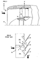
- FIG. 1 shows an aircraft gas turbine engine that includes an array of fan blades 20 each projecting radially from a hub 22 that is rotatable about an engine axis 24. A case circumscribes the tips of the blades to form a duct 26 that defines the radially outer boundary of a flowpath.
- a stream of working medium fluid S flows through the duct and past the blades.
- the duct internal wall includes an acoustic liner 30 residing axially forwardly of the blades for attenuating noise generated by the engine.
- the duct also includes a casing treatment 32 axially aligned with the blades for enhancing the aerodynamic stability of the blades.
- FIG. 1 shows both an acoustic liner and a stability enhancing casing treatment, the acoustic liner and the casing treatment can be used independently of each other.
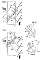
- FIG. 2 shows the blades 20 rotating in direction R and operating at a transonic condition.
- the Mach number of the fluid stream S is subsonic forward of the blades.
- the Mach number of the fluid stream relative to an observer moving with the blades is supersonic along the suction surface of each blade.
- An aerodynamic shock 34 extends in a shock orientation direction D from the suction surface of each blade.
- the shock orientation direction is approximately the same from the shock origin 36 to its terminus 38. Because of the subsonic conditions forward of the blades, the shock is locally confined and decays a short distance forward of the blade array. Although the shock decays rather than propagates, the direction P, which is perpendicular to the shock orientation direction D, may be referred to as the direction of shock propagation.
- FIG. 2 also shows that the acoustic liner 30 comprises two or more circumferentially extending segments 30a, 30b whose circumferentially adjacent edges are joined to each other by an axially extending splice 42.
- the splices do not necessarily possess the noise attenuating properties present in the rest of the acoustic liner, i.e. the acoustic impedance of the splices differs from the acoustic impedance of the rest of the acoustic liner. This mismatch in acoustic properties can scatter the energy of the decaying shocks into acoustic waves that propagate forwardly out of the duct even though the shocks themselves are locally confined.
- FIG. 3 illustrates a linear splice having a length L, a linear meanline 44 and a pair of edges 46a, 46b approximately equidistant from the meanline.
- the splice is oriented substantially perpendicular to the shock orientation direction D. Specifically, the splice is oriented so that the edges 46a, 46b are substantially perpendicular to the shock orientation direction D. Because the edges 46a, 46b are equidistant from the meanline, the splice orientation can also be described as one in which the edges or the meanline are substantially parallel to the direction of propagation P.
- the orientation of the splice reduces the mismatch in acoustic impedance in the direction perpendicular to the shock orientation direction D (i.e. in the direction parallel to the direction of shock propagation P).
- FIG. 3 shows the splice oriented perpendicular to the shock orientation direction D over the entire length L of the splice.
- the shock 34 decays a short distance forward of the blades, only the portion of the splice in region F, i.e. the portion that axially coincides with the footprint of the shock, need be oriented as described.
- the footprint of the shock is the projection of the shock (or at least of that portion of the shock responsible for noise propagation out of the duct) onto the acoustic liner.
- the portion of the splice not axially coincident with the shock footprint may be oriented differently.
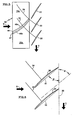
- FIG. 4 is similar to FIG. 3 but shows the blades 20 operating at a supersonic condition.
- the Mach number of the fluid stream S is supersonic both forward of the blades and along the suction surface of each blade.
- An aerodynamic shock 34 extends in a shock orientation direction D from the suction surface of each blade. Because of the supersonic conditions forward of the blades, the shock 34 of FIG. 4, unlike the shock 34 of FIGS. 2 and 3, is not locally confined. Instead, the shock shown in FIG. 4 propagates a considerable distance forwardly out of the duct in shock propagation direction P. Because the shock of FIG. 4 is not locally confined, a considerable variation in the shock orientation direction D can be observed along the shock.
- the shock propagation direction P which is locally perpendicular to the orientation direction D , likewise varies along the shock.
- the splice of FIG. 4 is oriented, over at least some of its length L, substantially perpendicular to the shock orientation direction D.
- the shock orientation direction D changes along the shock, so does the local orientation of the splice.
- the shock near the aft end of the acoustic liner, the shock locally forms an angle A with a circumferentially extending reference line 50.
- the shock forms a more acute angle B.
- the splice edges 46a, 46b are oriented more axially in the vicinity of angle B than they are in the vicinity of angle A. In the limit, as seen in FIG.
- the splice is curved so that its edges 46a, 46b are curved to be locally substantially perpendicular to the local shock orientation direction along the length of the splice.
- the meanline 44 is likewise curved. Although the illustration shows a splice whose edges are approximately equidistant from the meanline, a variable width splice with nonequidistant edges may also be used. The meanline would be curved even if the edges were nonequidistant.
- the above described curved splice may be approximated by a piecewise linear splice.
- the edges 46a, 46b are locally approximately perpendicular to the local shock orientation direction.
- the splices of FIGS. 4 and 5 like the splice of FIG. 3, need be oriented as described only where they coincide with the footprint of the shock. However because the shocks of FIGS. 4 and 5 are propagating shocks, rather than locally confined shocks, their footprint is expected to extend axially across the entire liner.
- the orientation of the splice edges for the configurations of FIGS. 3-5 can be determined from the shock structure at the operating condition corresponding to the greatest noise.
- This condition almost always differs from the aerodynamic design point of the engine and can be referred to as the acoustic design condition.
- the acoustic design condition typically occurs at a blade relative Mach number of about 1.2, where the shock lies just forward of the blade leading edge and is almost normal, i.e perpendicular to the blade chord line 51, which is a line extending from the leading edge to the trailing edge. Therefore, as a rough guideline, the orientation angle ⁇ equals the blade stagger angle ⁇ at the spanwise (i.e.
- the spanwise location of peak shock strength is usually at or near the blade tip.
- the effect of sweep and/or the effect of transitions from forward sweep to rearward sweep can cause the peak shock strength to occur radially inboard of the blade tip.
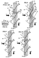
- FIGS. 7 and 7A show a casing treatment 32 comprising circumferentially extending grooves 52 residing in the case axially aligned with and radially outboard of the blades.
- the grooves are axially separated from each other by intergroove rails 54.
- the grooves and rails are interrupted by axially extending, circumferentially distributed interruptions in the form of partitions such as representative partition 56.
- the acoustic impedance of the partitions differs from the acoustic impedance of the grooves so that, like the acoustic splices described above, the partitions can cause shock related noise to propagate forwardly out of the duct.
- the partitions are linear and have a length L.
- the partitions are oriented, over at least a portion of their length, substantially perpendicular to the direction of shock orientation D, which is substantially parallel to the direction of shock propagation P.
- each partition is oriented so that its edges 56a, 56b are substantially perpendicular to the shock orientation direction D. Because the edges 56a, 56b are equidistant from partition meanline 60, the partition orientation can also be described as one in which the edges or the meanline are substantially parallel to the direction of propagation P.
- the orientation of the partition reduces the mismatch in acoustic impedance in the direction perpendicular to the shock orientation direction D (i.e. in the direction parallel to the direction of shock propagation P).
- the curved or piecewise linear concepts of FIGS. 4 and 5 respectively may be employed and may be attractive for shocks whose orientation direction D changes along the length of the shock.
- the partition may be a piecewise linear partition as seen in FIG. 9.
- the aft portion of the partition is not covered by the shock footprint and therefore is oriented axially.
- the forward portion of the partition is covered by the partition footprint and so is oriented so that its edges are perpendicular to the direction of shock orientation D, which is parallel to the direction of shock propagation P.
- FIG. 10 shows a variant similar to that of FIG. 9 in which the partition 56 is curved rather than piecewise linear.
- the aft portion of the partition is not covered by the shock footprint and therefore is oriented substantially axially.
- the forward portion of the partition is covered by the partition footprint and so is oriented so that its edges are approximately perpendicular to the direction of shock orientation D, which is parallel to the direction of shock propagation P.
- FIGS. 4 and 10 both show curved features (acoustic liner splices and a casing treatment partition respectively) the curvature changes in different directions.
- the splice turns progressively more toward the axial direction with increasing distance away from the blades (in the forward direction) in order to accommodate the fact that the shock itself has a varying orientation direction D.
- the partition of FIG. 10 turns more toward the circumferential direction with increasing distance away from the blades in order to accommodate the fact that the shock footprint covers only a forward portion of the casing treatment and undergoes little or no change in its direction of orientation along that forward portion of the casing treatment.
- the intent is to locally orient the splice or partition to be substantially perpendicular to the local direction of shock orientation. Similar observations apply to the piecewise linear features of FIGS 5. and 9.
Landscapes
- Engineering & Computer Science (AREA)
- Mechanical Engineering (AREA)
- General Engineering & Computer Science (AREA)
- Chemical & Material Sciences (AREA)
- Combustion & Propulsion (AREA)
- Aviation & Aerospace Engineering (AREA)
- Physics & Mathematics (AREA)
- Geometry (AREA)
- Structures Of Non-Positive Displacement Pumps (AREA)
- Pipe Accessories (AREA)
- Hydraulic Turbines (AREA)
Applications Claiming Priority (1)
| Application Number | Priority Date | Filing Date | Title |
|---|---|---|---|
| US11/267,241 US7861823B2 (en) | 2005-11-04 | 2005-11-04 | Duct for reducing shock related noise |
Publications (3)
| Publication Number | Publication Date |
|---|---|
| EP1783346A2 true EP1783346A2 (de) | 2007-05-09 |
| EP1783346A3 EP1783346A3 (de) | 2010-11-17 |
| EP1783346B1 EP1783346B1 (de) | 2018-01-10 |
Family
ID=37575210
Family Applications (1)
| Application Number | Title | Priority Date | Filing Date |
|---|---|---|---|
| EP06255672.5A Ceased EP1783346B1 (de) | 2005-11-04 | 2006-11-03 | Strömungskanal mit Mitteln zur Reduktion des von Stössen hervorgerufenen Rauschens |
Country Status (5)
| Country | Link |
|---|---|
| US (1) | US7861823B2 (de) |
| EP (1) | EP1783346B1 (de) |
| JP (1) | JP2007127122A (de) |
| CA (1) | CA2562452A1 (de) |
| IL (1) | IL179031A0 (de) |
Cited By (5)
| Publication number | Priority date | Publication date | Assignee | Title |
|---|---|---|---|---|
| EP2514975A3 (de) * | 2011-04-20 | 2014-06-11 | Rolls-Royce Deutschland Ltd & Co KG | Strömungsmaschine |
| WO2014111642A1 (fr) | 2013-01-18 | 2014-07-24 | Snecma | Manche d'entrée d'air acoustiquement optimisée |
| EP2937543A1 (de) * | 2014-04-25 | 2015-10-28 | Rolls-Royce plc | Einlass-auskleidung |
| US9512727B2 (en) | 2011-03-28 | 2016-12-06 | Rolls-Royce Deutschland Ltd & Co Kg | Rotor of an axial compressor stage of a turbomachine |
| US9822795B2 (en) | 2011-03-28 | 2017-11-21 | Rolls-Royce Deutschland Ltd & Co Kg | Stator of an axial compressor stage of a turbomachine |
Families Citing this family (22)
| Publication number | Priority date | Publication date | Assignee | Title |
|---|---|---|---|---|
| DE102004055439A1 (de) * | 2004-11-17 | 2006-05-24 | Rolls-Royce Deutschland Ltd & Co Kg | Strömungsarbeitsmaschine mit dynamischer Strömungsbeeinflussung |
| US7861823B2 (en) * | 2005-11-04 | 2011-01-04 | United Technologies Corporation | Duct for reducing shock related noise |
| US8602156B2 (en) * | 2006-05-19 | 2013-12-10 | United Technologies Corporation | Multi-splice acoustic liner |
| US7967105B2 (en) * | 2006-06-19 | 2011-06-28 | Yen Tuan | Aero-acoustic aviation engine inlet for aggressive noise abatement |
| DE102007037924A1 (de) * | 2007-08-10 | 2009-02-12 | Rolls-Royce Deutschland Ltd & Co Kg | Strömungsarbeitsmaschine mit Ringkanalwandausnehmung |
| DE102008011644A1 (de) * | 2008-02-28 | 2009-09-03 | Rolls-Royce Deutschland Ltd & Co Kg | Gehäusestrukturierung für Axialverdichter im Nabenbereich |
| DE102008031982A1 (de) * | 2008-07-07 | 2010-01-14 | Rolls-Royce Deutschland Ltd & Co Kg | Strömungsarbeitsmaschine mit Nut an einem Laufspalt eines Schaufelendes |
| DE102008037154A1 (de) | 2008-08-08 | 2010-02-11 | Rolls-Royce Deutschland Ltd & Co Kg | Strömungsarbeitsmaschine |
| GB0908128D0 (en) * | 2009-05-12 | 2009-06-24 | Rolls Royce Plc | An intake duct liner for a turbofan gas turbine engine |
| GB2483060B (en) * | 2010-08-23 | 2013-05-15 | Rolls Royce Plc | A turbomachine casing assembly |
| JP5804808B2 (ja) | 2011-07-07 | 2015-11-04 | 三菱日立パワーシステムズ株式会社 | ガスタービン燃焼器及びその燃焼振動減衰方法 |
| WO2014143280A1 (en) * | 2013-03-15 | 2014-09-18 | United Technologies Corporation | Gas turbine blade array with reduced acoustic output |
| US10145301B2 (en) | 2014-09-23 | 2018-12-04 | Pratt & Whitney Canada Corp. | Gas turbine engine inlet |
| US10378554B2 (en) | 2014-09-23 | 2019-08-13 | Pratt & Whitney Canada Corp. | Gas turbine engine with partial inlet vane |
| WO2016093811A1 (en) * | 2014-12-10 | 2016-06-16 | General Electric Company | Compressor end-wall treatment having a bent profile |
| US9938848B2 (en) | 2015-04-23 | 2018-04-10 | Pratt & Whitney Canada Corp. | Rotor assembly with wear member |
| US9957807B2 (en) | 2015-04-23 | 2018-05-01 | Pratt & Whitney Canada Corp. | Rotor assembly with scoop |
| US10724540B2 (en) | 2016-12-06 | 2020-07-28 | Pratt & Whitney Canada Corp. | Stator for a gas turbine engine fan |
| US10690146B2 (en) | 2017-01-05 | 2020-06-23 | Pratt & Whitney Canada Corp. | Turbofan nacelle assembly with flow disruptor |
| US11236764B2 (en) * | 2017-11-30 | 2022-02-01 | Aerojet Rocketdyne, Inc. | Pump with housing having internal grooves |
| CN112160943A (zh) * | 2020-10-13 | 2021-01-01 | 中国人民解放军海军工程大学 | 一种燃气轮机压气机机匣防喘结构及其喘振裕度评价方法 |
| US20230151825A1 (en) * | 2021-11-17 | 2023-05-18 | Pratt & Whitney Canada Corp. | Compressor shroud with swept grooves |
Family Cites Families (48)
| Publication number | Priority date | Publication date | Assignee | Title |
|---|---|---|---|---|
| US3184152A (en) * | 1959-07-06 | 1965-05-18 | Commissariat Energie Atomique | Supersonic compressors |
| US3508838A (en) | 1968-09-16 | 1970-04-28 | Gen Electric | Sound suppression of compressors used in gas turbine engines |
| US3574477A (en) * | 1969-02-19 | 1971-04-13 | Boeing Co | Noise attenuating system for rotary engines |
| US3761196A (en) * | 1971-08-26 | 1973-09-25 | E Weinert | Cavitation control system |
| US3883268A (en) * | 1971-11-01 | 1975-05-13 | Gen Electric | Blunted leading edge fan blade for noise reduction |
| US3850261A (en) * | 1973-03-01 | 1974-11-26 | Gen Electric | Wide band width single layer sound suppressing panel |
| US3873229A (en) * | 1973-12-26 | 1975-03-25 | United Aircraft Corp | Inlet guide vane configuration for noise control of supersonic fan |
| US3937590A (en) | 1974-09-03 | 1976-02-10 | General Electric Company | Acoustic duct with peripherally segmented acoustic treatment |
| US3989406A (en) | 1974-11-26 | 1976-11-02 | Bolt Beranek And Newman, Inc. | Method of and apparatus for preventing leading edge shocks and shock-related noise in transonic and supersonic rotor blades and the like |
| GB1518293A (en) * | 1975-09-25 | 1978-07-19 | Rolls Royce | Axial flow compressors particularly for gas turbine engines |
| GB1522558A (en) | 1976-04-05 | 1978-08-23 | Rolls Royce | Duct linings |
| US4104002A (en) * | 1976-12-02 | 1978-08-01 | General Electric Company | Spiral strip acoustic treatment |
| GB2017228B (en) * | 1977-07-14 | 1982-05-06 | Pratt & Witney Aircraft Of Can | Shroud for a turbine rotor |
| JPS6318799Y2 (de) * | 1980-12-02 | 1988-05-26 | ||
| GB2090334B (en) | 1980-12-29 | 1983-11-16 | Rolls Royce | Damping flutter of ducted fans |
| GB2146707B (en) | 1983-09-14 | 1987-08-05 | Rolls Royce | Turbine |
| US4645417A (en) | 1984-02-06 | 1987-02-24 | General Electric Company | Compressor casing recess |
| US4606699A (en) | 1984-02-06 | 1986-08-19 | General Electric Company | Compressor casing recess |
| GB2245312B (en) | 1984-06-19 | 1992-03-25 | Rolls Royce Plc | Axial flow compressor surge margin improvement |
| US4998039A (en) * | 1989-09-29 | 1991-03-05 | Amoco Corporation | Ultracompact flow loop with no rotating components |
| US5175401A (en) | 1991-03-18 | 1992-12-29 | Grumman Aerospace Corporation | Segmented resistance acoustic attenuating liner |
| DE59201833D1 (de) | 1991-10-08 | 1995-05-11 | Asea Brown Boveri | Deckband für axialdurchströmte Turbine. |
| EP0572725A1 (de) | 1992-06-03 | 1993-12-08 | Fokker Aircraft B.V. | Schalldämpfende Auskleidung |
| DE4340951A1 (de) | 1992-12-04 | 1994-06-09 | Grumman Aerospace Corp | Einstückiges Triebwerkeinlaß-Schallrohr |
| RU2034175C1 (ru) | 1993-03-11 | 1995-04-30 | Центральный институт авиационного моторостроения им.П.И.Баранова | Турбокомпрессор |
| JPH0712098A (ja) | 1993-06-28 | 1995-01-17 | Ishikawajima Harima Heavy Ind Co Ltd | 圧縮機ケーシング |
| EP0774050B1 (de) * | 1994-06-14 | 1999-03-10 | United Technologies Corporation | Statorstruktur mit unterbrochenen ringnuten |
| US5520508A (en) * | 1994-12-05 | 1996-05-28 | United Technologies Corporation | Compressor endwall treatment |
| JP3188128B2 (ja) * | 1995-02-21 | 2001-07-16 | 株式会社豊田中央研究所 | 車輌用トルクコンバータのステータ |
| JPH09170494A (ja) * | 1995-12-20 | 1997-06-30 | Ishikawajima Harima Heavy Ind Co Ltd | 吸音ライナ |
| US6139259A (en) * | 1998-10-29 | 2000-10-31 | General Electric Company | Low noise permeable airfoil |
| US6379110B1 (en) * | 1999-02-25 | 2002-04-30 | United Technologies Corporation | Passively driven acoustic jet controlling boundary layers |
| US6629831B2 (en) * | 1999-04-16 | 2003-10-07 | Coach Wei | Apparatus for altering the physical properties of fluids |
| US6409469B1 (en) * | 2000-11-21 | 2002-06-25 | Pratt & Whitney Canada Corp. | Fan-stator interaction tone reduction |
| GB0119608D0 (en) * | 2001-08-11 | 2001-10-03 | Rolls Royce Plc | A guide vane assembly |
| DE10205363A1 (de) | 2002-02-08 | 2003-08-21 | Rolls Royce Deutschland | Gasturbine |
| FR2844304B1 (fr) * | 2002-09-10 | 2004-12-10 | Airbus France | Couche acoustiquement resistive pour panneau d'attenuation acoustique, panneau utilisant une telle couche |
| GB0223697D0 (en) * | 2002-10-14 | 2002-11-20 | Rolls Royce Plc | Acoustic liner for gas turbine engineers |
| FR2847304B1 (fr) | 2002-11-18 | 2005-07-01 | Airbus France | Nacelle de reacteur d'aeronef a attenuation acoustique |
| DE10254824A1 (de) * | 2002-11-25 | 2004-06-09 | Alstom Technology Ltd | Ansaugschalldämpfer für Gasturbinen |
| DE10254825A1 (de) * | 2002-11-25 | 2004-06-03 | Alstom Technology Ltd | Wassersprühvorrichtung für Gasturbinen |
| US7631483B2 (en) * | 2003-09-22 | 2009-12-15 | General Electric Company | Method and system for reduction of jet engine noise |
| US7497300B2 (en) * | 2004-03-18 | 2009-03-03 | D Angelo John P | Noise reduction tubes |
| GB0415844D0 (en) * | 2004-07-15 | 2004-08-18 | Rolls Royce Plc | Noise control |
| US7104752B2 (en) * | 2004-10-28 | 2006-09-12 | Florida Turbine Technologies, Inc. | Braided wire damper for segmented stator/rotor and method |
| US7861823B2 (en) * | 2005-11-04 | 2011-01-04 | United Technologies Corporation | Duct for reducing shock related noise |
| GB0600532D0 (en) * | 2006-01-12 | 2006-02-22 | Rolls Royce Plc | A blade and rotor arrangement |
| US8602156B2 (en) * | 2006-05-19 | 2013-12-10 | United Technologies Corporation | Multi-splice acoustic liner |
-
2005
- 2005-11-04 US US11/267,241 patent/US7861823B2/en active Active
-
2006
- 2006-10-03 CA CA002562452A patent/CA2562452A1/en not_active Abandoned
- 2006-10-23 JP JP2006287101A patent/JP2007127122A/ja active Pending
- 2006-11-02 IL IL179031A patent/IL179031A0/en unknown
- 2006-11-03 EP EP06255672.5A patent/EP1783346B1/de not_active Ceased
Cited By (8)
| Publication number | Priority date | Publication date | Assignee | Title |
|---|---|---|---|---|
| US9512727B2 (en) | 2011-03-28 | 2016-12-06 | Rolls-Royce Deutschland Ltd & Co Kg | Rotor of an axial compressor stage of a turbomachine |
| US9822795B2 (en) | 2011-03-28 | 2017-11-21 | Rolls-Royce Deutschland Ltd & Co Kg | Stator of an axial compressor stage of a turbomachine |
| EP2514975A3 (de) * | 2011-04-20 | 2014-06-11 | Rolls-Royce Deutschland Ltd & Co KG | Strömungsmaschine |
| US9816528B2 (en) | 2011-04-20 | 2017-11-14 | Rolls-Royce Deutschland Ltd & Co Kg | Fluid-flow machine |
| WO2014111642A1 (fr) | 2013-01-18 | 2014-07-24 | Snecma | Manche d'entrée d'air acoustiquement optimisée |
| US10024236B2 (en) | 2013-01-18 | 2018-07-17 | Snecma | Acoustically optimized air inlet |
| EP2937543A1 (de) * | 2014-04-25 | 2015-10-28 | Rolls-Royce plc | Einlass-auskleidung |
| US10330014B2 (en) | 2014-04-25 | 2019-06-25 | Rolls-Royce Plc | Intake liner |
Also Published As
| Publication number | Publication date |
|---|---|
| US7861823B2 (en) | 2011-01-04 |
| EP1783346B1 (de) | 2018-01-10 |
| IL179031A0 (en) | 2007-09-20 |
| CA2562452A1 (en) | 2007-05-04 |
| JP2007127122A (ja) | 2007-05-24 |
| US20070102234A1 (en) | 2007-05-10 |
| EP1783346A3 (de) | 2010-11-17 |
Similar Documents
| Publication | Publication Date | Title |
|---|---|---|
| EP1783346B1 (de) | Strömungskanal mit Mitteln zur Reduktion des von Stössen hervorgerufenen Rauschens | |
| USRE43710E1 (en) | Swept turbomachinery blade | |
| EP1152122B1 (de) | Beschaufelung einer Turbomaschine | |
| US6338609B1 (en) | Convex compressor casing | |
| US11377958B2 (en) | Turbomachine fan flow-straightener vane, turbomachine assembly comprising such a vane and turbomachine equipped with said vane or said assembly | |
| US10344711B2 (en) | System and method of alleviating blade flutter | |
| US20200400069A1 (en) | Turbine engine with a flow splitter having a profile with inclined serrations | |
| US8221081B2 (en) | Turbomachine having an unducted fan provided with air guide means | |
| US20130008170A1 (en) | Subsonic swept fan blade | |
| US11353038B2 (en) | Compressor rotor for supersonic flutter and/or resonant stress mitigation | |
| JP3640396B2 (ja) | 分断された周方向溝付きステータ構造体 | |
| AU2003207098A1 (en) | Fan | |
| US20170370374A1 (en) | Compressor rotor airfoil | |
| US10408227B2 (en) | Airfoil with stress-reducing fillet adapted for use in a gas turbine engine | |
| CA2893242C (en) | Rotary airfoil with forward sweep | |
| JP4045993B2 (ja) | ファン静翼、航空エンジン用ファン、及び航空エンジン | |
| WO2019069374A1 (ja) | プロペラファンおよび軸流送風機 | |
| US20210340992A1 (en) | Blade and axial flow impeller using same |
Legal Events
| Date | Code | Title | Description |
|---|---|---|---|
| PUAI | Public reference made under article 153(3) epc to a published international application that has entered the european phase |
Free format text: ORIGINAL CODE: 0009012 |
|
| AK | Designated contracting states |
Kind code of ref document: A2 Designated state(s): AT BE BG CH CY CZ DE DK EE ES FI FR GB GR HU IE IS IT LI LT LU LV MC NL PL PT RO SE SI SK TR |
|
| AX | Request for extension of the european patent |
Extension state: AL BA HR MK YU |
|
| PUAL | Search report despatched |
Free format text: ORIGINAL CODE: 0009013 |
|
| AK | Designated contracting states |
Kind code of ref document: A3 Designated state(s): AT BE BG CH CY CZ DE DK EE ES FI FR GB GR HU IE IS IT LI LT LU LV MC NL PL PT RO SE SI SK TR |
|
| AX | Request for extension of the european patent |
Extension state: AL BA HR MK RS |
|
| RIC1 | Information provided on ipc code assigned before grant |
Ipc: F02K 3/06 20060101ALI20101008BHEP Ipc: F01D 9/06 20060101ALI20101008BHEP Ipc: F04D 29/66 20060101ALI20101008BHEP Ipc: F02C 7/045 20060101AFI20070201BHEP |
|
| 17P | Request for examination filed |
Effective date: 20110517 |
|
| AKX | Designation fees paid |
Designated state(s): DE GB |
|
| 17Q | First examination report despatched |
Effective date: 20141210 |
|
| RAP1 | Party data changed (applicant data changed or rights of an application transferred) |
Owner name: UNITED TECHNOLOGIES CORPORATION |
|
| GRAP | Despatch of communication of intention to grant a patent |
Free format text: ORIGINAL CODE: EPIDOSNIGR1 |
|
| STAA | Information on the status of an ep patent application or granted ep patent |
Free format text: STATUS: GRANT OF PATENT IS INTENDED |
|
| INTG | Intention to grant announced |
Effective date: 20170707 |
|
| GRAJ | Information related to disapproval of communication of intention to grant by the applicant or resumption of examination proceedings by the epo deleted |
Free format text: ORIGINAL CODE: EPIDOSDIGR1 |
|
| GRAL | Information related to payment of fee for publishing/printing deleted |
Free format text: ORIGINAL CODE: EPIDOSDIGR3 |
|
| STAA | Information on the status of an ep patent application or granted ep patent |
Free format text: STATUS: EXAMINATION IS IN PROGRESS |
|
| GRAS | Grant fee paid |
Free format text: ORIGINAL CODE: EPIDOSNIGR3 |
|
| GRAR | Information related to intention to grant a patent recorded |
Free format text: ORIGINAL CODE: EPIDOSNIGR71 |
|
| STAA | Information on the status of an ep patent application or granted ep patent |
Free format text: STATUS: GRANT OF PATENT IS INTENDED |
|
| GRAA | (expected) grant |
Free format text: ORIGINAL CODE: 0009210 |
|
| STAA | Information on the status of an ep patent application or granted ep patent |
Free format text: STATUS: THE PATENT HAS BEEN GRANTED |
|
| INTC | Intention to grant announced (deleted) | ||
| AK | Designated contracting states |
Kind code of ref document: B1 Designated state(s): DE GB |
|
| INTG | Intention to grant announced |
Effective date: 20171204 |
|
| REG | Reference to a national code |
Ref country code: GB Ref legal event code: FG4D |
|
| REG | Reference to a national code |
Ref country code: DE Ref legal event code: R082 Ref document number: 602006054512 Country of ref document: DE Representative=s name: SCHMITT-NILSON SCHRAUD WAIBEL WOHLFROM PATENTA, DE |
|
| REG | Reference to a national code |
Ref country code: DE Ref legal event code: R096 Ref document number: 602006054512 Country of ref document: DE |
|
| REG | Reference to a national code |
Ref country code: DE Ref legal event code: R097 Ref document number: 602006054512 Country of ref document: DE |
|
| PLBE | No opposition filed within time limit |
Free format text: ORIGINAL CODE: 0009261 |
|
| STAA | Information on the status of an ep patent application or granted ep patent |
Free format text: STATUS: NO OPPOSITION FILED WITHIN TIME LIMIT |
|
| 26N | No opposition filed |
Effective date: 20181011 |
|
| PGFP | Annual fee paid to national office [announced via postgrant information from national office to epo] |
Ref country code: DE Payment date: 20201020 Year of fee payment: 15 |
|
| REG | Reference to a national code |
Ref country code: DE Ref legal event code: R119 Ref document number: 602006054512 Country of ref document: DE |
|
| PG25 | Lapsed in a contracting state [announced via postgrant information from national office to epo] |
Ref country code: DE Free format text: LAPSE BECAUSE OF NON-PAYMENT OF DUE FEES Effective date: 20220601 |
|
| PGFP | Annual fee paid to national office [announced via postgrant information from national office to epo] |
Ref country code: GB Payment date: 20231019 Year of fee payment: 18 |
|
| GBPC | Gb: european patent ceased through non-payment of renewal fee |
Effective date: 20241103 |
|
| PG25 | Lapsed in a contracting state [announced via postgrant information from national office to epo] |
Ref country code: GB Free format text: LAPSE BECAUSE OF NON-PAYMENT OF DUE FEES Effective date: 20241103 |