EP1783371A1 - Elektropumpeneinheit - Google Patents
Elektropumpeneinheit Download PDFInfo
- Publication number
- EP1783371A1 EP1783371A1 EP06291732A EP06291732A EP1783371A1 EP 1783371 A1 EP1783371 A1 EP 1783371A1 EP 06291732 A EP06291732 A EP 06291732A EP 06291732 A EP06291732 A EP 06291732A EP 1783371 A1 EP1783371 A1 EP 1783371A1
- Authority
- EP
- European Patent Office
- Prior art keywords
- pumps
- electro
- pump unit
- pump
- common
- Prior art date
- Legal status (The legal status is an assumption and is not a legal conclusion. Google has not performed a legal analysis and makes no representation as to the accuracy of the status listed.)
- Granted
Links
Images




Classifications
-
- F—MECHANICAL ENGINEERING; LIGHTING; HEATING; WEAPONS; BLASTING
- F04—POSITIVE - DISPLACEMENT MACHINES FOR LIQUIDS; PUMPS FOR LIQUIDS OR ELASTIC FLUIDS
- F04C—ROTARY-PISTON, OR OSCILLATING-PISTON, POSITIVE-DISPLACEMENT MACHINES FOR LIQUIDS; ROTARY-PISTON, OR OSCILLATING-PISTON, POSITIVE-DISPLACEMENT PUMPS
- F04C11/00—Combinations of two or more machines or pumps, each being of rotary-piston or oscillating-piston type; Pumping installations
- F04C11/001—Combinations of two or more machines or pumps, each being of rotary-piston or oscillating-piston type; Pumping installations of similar working principle
-
- F—MECHANICAL ENGINEERING; LIGHTING; HEATING; WEAPONS; BLASTING
- F04—POSITIVE - DISPLACEMENT MACHINES FOR LIQUIDS; PUMPS FOR LIQUIDS OR ELASTIC FLUIDS
- F04C—ROTARY-PISTON, OR OSCILLATING-PISTON, POSITIVE-DISPLACEMENT MACHINES FOR LIQUIDS; ROTARY-PISTON, OR OSCILLATING-PISTON, POSITIVE-DISPLACEMENT PUMPS
- F04C2/00—Rotary-piston machines or pumps
- F04C2/08—Rotary-piston machines or pumps of intermeshing-engagement type, i.e. with engagement of co-operating members similar to that of toothed gearing
- F04C2/10—Rotary-piston machines or pumps of intermeshing-engagement type, i.e. with engagement of co-operating members similar to that of toothed gearing of internal-axis type with the outer member having more teeth or tooth-equivalents, e.g. rollers, than the inner member
-
- F—MECHANICAL ENGINEERING; LIGHTING; HEATING; WEAPONS; BLASTING
- F04—POSITIVE - DISPLACEMENT MACHINES FOR LIQUIDS; PUMPS FOR LIQUIDS OR ELASTIC FLUIDS
- F04C—ROTARY-PISTON, OR OSCILLATING-PISTON, POSITIVE-DISPLACEMENT MACHINES FOR LIQUIDS; ROTARY-PISTON, OR OSCILLATING-PISTON, POSITIVE-DISPLACEMENT PUMPS
- F04C2/00—Rotary-piston machines or pumps
- F04C2/08—Rotary-piston machines or pumps of intermeshing-engagement type, i.e. with engagement of co-operating members similar to that of toothed gearing
- F04C2/12—Rotary-piston machines or pumps of intermeshing-engagement type, i.e. with engagement of co-operating members similar to that of toothed gearing of other than internal-axis type
- F04C2/14—Rotary-piston machines or pumps of intermeshing-engagement type, i.e. with engagement of co-operating members similar to that of toothed gearing of other than internal-axis type with toothed rotary pistons
- F04C2/18—Rotary-piston machines or pumps of intermeshing-engagement type, i.e. with engagement of co-operating members similar to that of toothed gearing of other than internal-axis type with toothed rotary pistons with similar tooth forms
Definitions
- the invention relates to an electropump, of the type comprising at least one hydraulic pump, in particular gear, driven in rotation by a motor device.
- Electro-pumps of this type which are known and in particular used by the power steering of a motor vehicle, have the major disadvantage that the power of the group is limited although the vehicles to be equipped with a power steering are becoming heavier and the powers necessary to ensure the power steering are higher and higher.
- the power of the electric pump units is limited for technological reasons, in particular because the power supply and the connectors do not accept a sufficient intensity, as the technology of high power engines (> 1.5 kW ) is almost non-existent for a voltage of 12V and that the development of such motors is limited to low series and has a high cost.
- the invention aims to overcome the drawback of known systems.
- the electro-pump unit according to the invention is characterized in that it comprises two hydraulic pumps and two electric motors which are arranged so that the power of the group can be obtained by adding the powers of the two. engines.
- the electropump is characterized in that it comprises a discharge manifold which comprises a discharge channel common to both pumps.
- the electric pump unit is characterized in that the two pumps are integrated in a common pump body.
- the electro-pump unit is characterized in that comprises a suction manifold having a suction channel common to both pumps.
- the electric pump unit is characterized in that the drive motors of the two pumps are arranged on either side of the common pump body.
- the electric pump unit is characterized in that the pump body is sandwiched between the suction manifold and the discharge manifold, each manifold bearing on its outer face one of the two engines.
- the electric pump unit is characterized in that the pump body comprises, inside an outer casing wall, a high pressure volume common to both pumps, which communicates with the working chambers of the two pumps and a common high pressure volume provided in the discharge manifold, which is in communication with the common discharge channel.
- the electro-pump unit is characterized in that it comprises a common support sole which comprises, inside, the common discharge channel and on one side of which are mounted the two pumps and on the other two engines.
- the electropump is characterized in that the two pumps are enclosed in a common liner capable of constituting a low pressure liquid reservoir.
- the electro-pump unit is characterized in that at least one of the pumps comprises, in its discharge path a non-return valve so that this pump can be selectively stopped.
- the electric pump unit is characterized in that it comprises an engine control device adapted to control one engine from the outside and that engine controls the speed of the other.
- the electric pump unit is characterized in that the two motors rotate in the same direction or in opposite directions.
- the electro-pump unit is characterized in that the two pumps are adapted to rotate with an angular offset of a few degrees to provide a decrease in the pressure pulsations produced by the electro-pump unit.
- the electric pump unit is characterized in that the two pumps are capable of operating in phase opposition.
- the electric pump unit is characterized in that the pumps operate at different speeds of rotation.
- the electric pump unit is characterized in that the presence of two motors constitutes a redundancy security means.
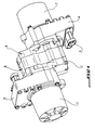
- FIG. 1 is an overview of an electric pump unit according to the invention, which comprises two electric motors and two hydraulic pumps, each driven by one of the two motors.
- the references 1 and 2 designate the two electric motors
- the reference B the pump body which encloses two hydraulic gear pumps
- the inlet or suction manifold of the pumps and C the outlet manifold or of repression.
- the pump body B is sandwiched between the inlet manifolds A and outlet C.
- Each motor has a base portion respectively 4 and 5 which carries the electrical connections 6 of the motors and encloses the electrical circuits.
- FIG. 19 gives the block diagram of the system according to FIG. 1. It can be seen that the motor 1 drives a first pump designated by the reference 8 and the second the motor 2 a second pump 9. The two pumps 8 and 9 suck up the hydraulic fluid in a tank 10. The discharge paths of the two pumps are joined at the junction point 14 and thus supply the user in high pressure hydraulic fluid, generally in oil. In the discharge line of each pump upstream of the junction point 14 is provided a check valve 12. A pressure limiter 11 and a feed valve 13 are mounted in parallel between the junction point 14 and the reservoir.
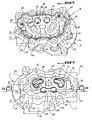
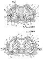
- FIG. 3 illustrates the structure of the suction manifold A and also shows the pinions of the gear trains of the two pumps 8 and 9, noted for the pump 8 and 16 for the pump 9, the pinions being shown with their lower bearings. 17 and above 18.
- the presentation of the manifold or suction support A is completed by the two sectional views 6 and 7 which are taken along the lines VI-VI and VII-VII shown in FIG.
- the suction manifold A comprises a suction channel 20 which opens outwards into the lateral face 21.
- This channel 20 which is rectilinear as can be seen in FIGS. 6 and 7, communicates with low-pressure capacitive cavities 23, 24 of the manifold from the inner face 25 for receiving the pump body B.
- This suction channel 20 is connected to a reservoir 10 according to Figure 19, outside the electropump.
- the cavity 23 near the pinions 16 of the pump 9 is wider and deeper than the cavity 24 on the side of the other pump, which is in the form of an arcuate groove.
- the cavity 23 has a raised bottom intermediate zone 23 'which delimits a cavity 26 for receiving the spring 27 of the pressure limiter 11 (FIG. 19).
- the suction channel 20 opens directly into the cavity 23 and communicates with the cavity 24 by a vertical channel 28, that is to say perpendicular to the section plane.
- Figure 7 further shows at 30 grooves in which are placed unrepresented seals.
- the reference 25 designates the installation face of the pump body B.
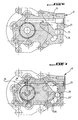
- Figures 4, 8 and 9 show that the pump body B has a bottom wall 32 which rests on the installation face 25 of the suction manifold A and on which rises an outer casing wall 33, and the interior of this envelope of peninsulas 35, 36 which delimit chambers 37, 38 housing the gear trains 15, 16 and bearings 17, 18, parts in the form of peduncles 39 of attachment of presqu'Ilots at the envelope wall 33 configured for producing two cylindrical housings 40, 41 of the two check valves 12 ( Figure 19) and the housing 39 in alignment with the cavity 26 for receiving the pressure limiter 11 (Figure 19).
- the envelope wall 33 has a boss which delimits a cavity 43 intended to receive the feedback valve 13 (FIG. 19).
- the remainder of the space inside the envelope wall 33 constitutes a capacitive volume comprising four cavities 45, 46, 47, 48 separated from each other only by the peduncle-shaped portions and two narrow ribs 49 of attachment of the penlets to the envelope wall.
- the front face and the surfaces of the presqu'Ilots, peduncles and ribs constitute the exposure face 34 for manifold C.
- the sectional views parallel to the plane of the pump body of FIGS. 8 and 9 show the inlet channels 50 and 51 of the chambers 37 and 38 for housing the gear trains with the bearings of the two pumps and the outlet channels 53 and 54.
- the inlet channel 51 communicates with the low pressure cavity 23 in which the suction channel 20 opens.
- the channel input 50 is connected to the suction channel 20 in a corresponding manner, not shown specifically.
- Figure 12 also shows that the outlet channel 54 communicates with the housing 41 of one of the two check valves 12, through the orifice 52 of the seat of the ball 55 of the valve.
- the ball 55 is pushed back onto its seat by a return spring 57 resting at its other end on a bearing base 58 being guided by a member in the form of a rod 59 of the valve, disposed in the center of the housing 41.
- the outlet channel 53 communicates in the same way with the housing 40 of the other non-return valve 12.
- FIGS. 10 and 11 illustrate the structure of the manifold or pressure support C.
- the discharge manifold C comprises a bottom wall 60 on which is raised perpendicularly an outer casing wall 61 which encloses a common capacitive volume 63.
- the front face 62 of this wall is intended to bear on the front face of installation of the pump body 34.
- the volume 63 surrounds two islands 65, 66 for supporting the upper bearings 18 of the two gear trains, these islands are connected to each other by a relatively thin bar 67 and, at the of this bar, to the casing wall 61 by a raised area 68.
- This area has two circular projections 69 to the level of the laying plane of the manifold. These zones 69 are intended to serve as a bearing surface, each at the base of a base 58 of spring support of a nonreturn valve 12.
- FIGS. 13 and 14 it can be seen that the housing cavities 40, 41 of the pump body B communicate with the volume 63 of the discharge manifold C, by passages indicated at 72 on the part of and other and around the projections 69 of support of the check valves.
- FIG. 10 shows that the capacitive volume 63 is in communication with a high-pressure outlet channel 75 which opens out into the side wall 76 of the discharge manifold C.
- a high-pressure outlet channel 75 which opens out into the side wall 76 of the discharge manifold C.
- opening towards the outside of the outlet channel that is to say of repression, is not visible, but one recognizes at the bottom of the volume 63 in 77 the opening of the channel 75 in the volume 63.
- the discharge outlet manifold C comes, in the assembled state, by its upper face 62 bearing on the upper face 34 of the pump body B, the cavities 45, 46, 47 and 48 of the body B and the volume 63 of the discharge manifold C constitute a single volume filled with the high-pressure oil discharged by the pumps 8 and 9 through the discharge channels 53 and 54 (FIG. 9) via the non-return valves 12 arranged in the chambers 40, 41.
- the pressure limiter 11 (FIG. 19) it is placed in the cavity 26 of the suction manifold A (FIGS. 3, 6, 7) and the cavity 39 of the pump body B (FIGS. 4, 8, 9).
- the bottom of the cavity 26 is in communication with the low pressure suction space 23, by a not shown channel and the cavity 39 of the pump body B communicates via a channel 75 visible in FIGS. 8 and 9 with the high pressure cavity. 48 and thus with the discharge channel 75 via the volume 63 of the discharge manifold C.
- the refilling valve 13 it is housed in the cavity 43 of the pump body B (FIGS. 4, 8, 9) which communicates, as can be seen in FIG. 13, with the low-pressure groove 24 of the manifold. on the one hand, and on the other hand, the volume 63 of the discharge manifold C.
- the two motors 1 and 2 are arranged on either side of the assembly formed by the two pumps and comprising the suction manifolds A and discharge C and sandwiched between these two manifolds, the pump body B.
- Figure 3 there is shown at 80 the drive shaft of the motor 2, which is intended to pass through the bore 81 visible in the island 66 of the discharge manifold C.
- the drive of the gear train 15 of the pump 8 it is driven by the motor 1 whose shaft will then cross the bottom wall of the suction manifold A.
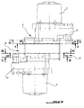
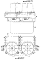
- FIG. 15 to 18 illustrate a second embodiment of the electro-pump system system according to the invention.
- This embodiment also comprises two motors denoted 1 and 2, each intended for driving a hydraulic gear pump, for example of the type described in the patent application. European EP 1 026 392 .
- These two pumps designated by the references 8 and 9, as in the first embodiment, are mounted on one side of a common support sole 83 and enclosed in a jacket 84 which delimits a low pressure liquid reservoir.
- the two motors 1, 2 are mounted on the other side of the support sole 83.
- FIG. 17 shows at 86 the motor shafts of the motors 1 and 2, at 87 the driving shafts driven in rotation by the motor shafts 86.
- the common support 83 for pumps and motors comprises a channel 89 which opens outwards into the lateral face 90 of the support and extends inside the support, passing under the pump 8 to the pump 9.
- the discharge channels of the high pressure liquid, designated by the reference 92, of the two pumps open into the channel 89 which is therefore the common discharge channel of the two pumps and thus the system according to the invention. 'invention.
- the invention therefore consists in using two motors which are controlled to be able to add the available powers of the two pumps.
- the invention also makes it possible to drive two different and uncoupled pumps to increase the difference between the minimum and maximum flow of the electropump. Pumps are generally limited in minimum flow because it is necessary to operate them at a minimum speed, the use of two pumps and two motors allows during low flow requests, not operate a motor and reduce power consumption. Thanks to the presence of a non-return valve at the outlet of the pumps, one of the two pumps can be stopped.
- the invention makes it possible to use engines that are widely used in series and to provide redundancy between the two motors, which makes it possible to avoid stopping power assistance in the event of a failure of one of the engines.
- the engine control it is performed from the instructions of the vehicle that the electro-pump group team.
- the steering could be provided by one of the two engines which would then drive the speed of the second.
- each pump generates pulsations of a frequency equal to the number of teeth multiplied by the rotation frequency of the pump.
- the motor control could be carried out to obtain a functioning of the pumps in opposition of phase. We could also drive the engines at different speeds.
- the invention makes it possible, by integrating the functions of the two pumps into a common pump body, to reduce the bulk of the group, while providing a large common high pressure volume, which provides, despite the presence of two pump units, a considerable improvement in the damping pulsations produced by these pumps.
Landscapes
- Engineering & Computer Science (AREA)
- Mechanical Engineering (AREA)
- General Engineering & Computer Science (AREA)
- Rotary Pumps (AREA)
- Details And Applications Of Rotary Liquid Pumps (AREA)
Applications Claiming Priority (1)
| Application Number | Priority Date | Filing Date | Title |
|---|---|---|---|
| FR0511333A FR2893092B1 (fr) | 2005-11-08 | 2005-11-08 | Groupe electro-pompe, du type comprenant au moins une pompe hydraulique, notamment a engrenage, entrainee en rotation par un dispositif moteur |
Publications (2)
| Publication Number | Publication Date |
|---|---|
| EP1783371A1 true EP1783371A1 (de) | 2007-05-09 |
| EP1783371B1 EP1783371B1 (de) | 2009-08-05 |
Family
ID=36726582
Family Applications (1)
| Application Number | Title | Priority Date | Filing Date |
|---|---|---|---|
| EP06291732A Ceased EP1783371B1 (de) | 2005-11-08 | 2006-11-07 | Elektropumpeneinheit |
Country Status (4)
| Country | Link |
|---|---|
| US (1) | US7942649B2 (de) |
| EP (1) | EP1783371B1 (de) |
| DE (1) | DE602006008244D1 (de) |
| FR (1) | FR2893092B1 (de) |
Cited By (2)
| Publication number | Priority date | Publication date | Assignee | Title |
|---|---|---|---|---|
| FR3041045A1 (fr) * | 2015-09-16 | 2017-03-17 | Jtekt Hpi | Agencement d'au moins deux dispositifs de pompes hydrauliques |
| EP2657499A3 (de) * | 2012-04-26 | 2018-01-03 | IHI Aerospace Co., Ltd. | Flüssigkeitszuführvorrichtung |
Families Citing this family (14)
| Publication number | Priority date | Publication date | Assignee | Title |
|---|---|---|---|---|
| US9562534B2 (en) | 2012-05-04 | 2017-02-07 | Ghsp, Inc. | In-line dual pump and motor with control device |
| US9115720B2 (en) | 2012-05-04 | 2015-08-25 | Ghsp, Inc. | Dual pump and motor with control device |
| US9752590B2 (en) | 2013-03-13 | 2017-09-05 | Ghsp, Inc. | Two pump design with coplanar interface surface |
| US11015585B2 (en) | 2014-05-01 | 2021-05-25 | Ghsp, Inc. | Submersible pump assembly |
| US10087927B2 (en) | 2014-05-01 | 2018-10-02 | Ghsp, Inc. | Electric motor with flux collector |
| DE102016107447A1 (de) * | 2016-04-21 | 2017-11-09 | Schwäbische Hüttenwerke Automotive GmbH | Rotationspumpe mit Schmiernut im Dichtsteg |
| DE102016113366A1 (de) * | 2016-07-20 | 2018-01-25 | Weber-Hydraulik Gmbh | Hydraulikaggregat |
| DE102017208373A1 (de) * | 2017-05-18 | 2018-11-22 | Continental Teves Ag & Co. Ohg | Druckbereitstellunganordnung sowie korrespondierendes Verfahren und Verwendung |
| JP6594381B2 (ja) * | 2017-08-10 | 2019-10-23 | 本田技研工業株式会社 | 油圧制御装置 |
| US10557480B1 (en) * | 2018-12-06 | 2020-02-11 | Razmik David Gharakhanian | Pumping systems and methods |
| DE102019111980A1 (de) * | 2019-05-08 | 2020-11-12 | Rapa Automotive Gmbh & Co. Kg | Energieversorgungseinheit für aktives fahrwerksystem |
| DE102019118384A1 (de) * | 2019-07-08 | 2021-01-14 | Rapa Automotive Gmbh & Co. Kg | Mpe-achssatz mit gemeinsamer ecu |
| ES2969297T3 (es) * | 2020-02-13 | 2024-05-17 | Entecnia Consulting S L | Conexión de brida para bombas de vacío |
| US12313056B2 (en) | 2022-12-27 | 2025-05-27 | Razmik David Gharakhanian | Pumping system |
Citations (4)
| Publication number | Priority date | Publication date | Assignee | Title |
|---|---|---|---|---|
| GB2023731A (en) * | 1978-05-29 | 1980-01-03 | Pumpen & Verdichter Veb K | Multi-stage centrifugal pump |
| JPH07243393A (ja) * | 1994-03-01 | 1995-09-19 | Ebara Corp | ポンプユニット |
| JPH07243392A (ja) * | 1994-03-01 | 1995-09-19 | Ebara Corp | ポンプユニット |
| US20020063354A1 (en) * | 2000-04-25 | 2002-05-30 | Hans-Michael Sulzbach | Process and device for pressurizing flowable reaction components |
Family Cites Families (8)
| Publication number | Priority date | Publication date | Assignee | Title |
|---|---|---|---|---|
| US2811930A (en) * | 1952-06-18 | 1957-11-05 | Borg Warner | Air motor governor |
| US2812715A (en) * | 1954-06-23 | 1957-11-12 | Westinghouse Electric Corp | Fuel system |
| DE1808411C3 (de) * | 1968-11-12 | 1973-08-16 | Jochen Dipl Ing Oplaender | Pumpenaggregat aus zwei in einem gehaeuse angeordneten kreiselpumpen |
| DE4021410A1 (de) * | 1990-07-06 | 1992-01-16 | Oplaender Wilo Werk Gmbh | Doppel-kreiselpumpe |
| CA2107523C (en) * | 1993-10-01 | 2004-05-04 | Gary D. Langeman | Plural component delivery system |
| US6726465B2 (en) * | 1996-03-22 | 2004-04-27 | Rodney J. Groleau | Injection molding machine employing a flow path gear pump and method of use |
| FR2789446B1 (fr) | 1999-02-04 | 2002-03-08 | Hydroperfect Internat Hpi | Pompe hydraulique du type a engrenage et groupe electro-pompe equipe d'une telle pompe |
| US7517200B2 (en) * | 2004-06-24 | 2009-04-14 | Caterpillar Inc. | Variable discharge fuel pump |
-
2005
- 2005-11-08 FR FR0511333A patent/FR2893092B1/fr not_active Expired - Fee Related
-
2006
- 2006-11-07 EP EP06291732A patent/EP1783371B1/de not_active Ceased
- 2006-11-07 US US11/593,749 patent/US7942649B2/en active Active
- 2006-11-07 DE DE602006008244T patent/DE602006008244D1/de active Active
Patent Citations (4)
| Publication number | Priority date | Publication date | Assignee | Title |
|---|---|---|---|---|
| GB2023731A (en) * | 1978-05-29 | 1980-01-03 | Pumpen & Verdichter Veb K | Multi-stage centrifugal pump |
| JPH07243393A (ja) * | 1994-03-01 | 1995-09-19 | Ebara Corp | ポンプユニット |
| JPH07243392A (ja) * | 1994-03-01 | 1995-09-19 | Ebara Corp | ポンプユニット |
| US20020063354A1 (en) * | 2000-04-25 | 2002-05-30 | Hans-Michael Sulzbach | Process and device for pressurizing flowable reaction components |
Cited By (3)
| Publication number | Priority date | Publication date | Assignee | Title |
|---|---|---|---|---|
| EP2657499A3 (de) * | 2012-04-26 | 2018-01-03 | IHI Aerospace Co., Ltd. | Flüssigkeitszuführvorrichtung |
| FR3041045A1 (fr) * | 2015-09-16 | 2017-03-17 | Jtekt Hpi | Agencement d'au moins deux dispositifs de pompes hydrauliques |
| EP3144472A1 (de) * | 2015-09-16 | 2017-03-22 | Jtekt Hpi | Anordnung von mindestens zwei vorrichtungen von hydraulischen pumpen |
Also Published As
| Publication number | Publication date |
|---|---|
| US7942649B2 (en) | 2011-05-17 |
| DE602006008244D1 (de) | 2009-09-17 |
| FR2893092B1 (fr) | 2008-10-10 |
| EP1783371B1 (de) | 2009-08-05 |
| FR2893092A1 (fr) | 2007-05-11 |
| US20070122298A1 (en) | 2007-05-31 |
Similar Documents
| Publication | Publication Date | Title |
|---|---|---|
| EP1783371B1 (de) | Elektropumpeneinheit | |
| EP2486262B1 (de) | Schaltung zur zuführung von kraftstoff an ein flugzeugtriebwerk | |
| EP3030775B1 (de) | Vorrichtung zum zuführen eines raketenmotortreibstoffes | |
| EP3892484A1 (de) | Antriebssystem für elektrofahrzeug | |
| FR2964171A1 (fr) | Vanne multivoies et circuit de fluides pourvu d'une telle vanne | |
| FR2689185A1 (fr) | Ensemble à pompe à huile pour moteur. | |
| FR2546981A1 (fr) | Machine hydraulique comprenant deux pompes ou moteurs a engrenages | |
| FR2834317A1 (fr) | Pompe | |
| FR2522739A1 (fr) | Transducteur de puissance hydraulique | |
| FR2826063A1 (fr) | Pompe a haute pression de carburant pour un moteur a combustion interne a charge partielle amelioree | |
| EP3144472B1 (de) | Anordnung von mindestens zwei vorrichtungen von hydraulischen pumpen | |
| FR2767932A1 (fr) | Dispositif de regulation de debit volumique et systeme d'injection comportant un tel dispositif de regulation, notamment pour moteur a combustion interne | |
| FR2865776A1 (fr) | Systeme d'injection de carburant pour un moteur a combustion interne | |
| EP3685075B1 (de) | Versorgungseinheit für mindestens eine hydraulische maschine | |
| US8708676B1 (en) | Drive system having a variable output gerotor pump | |
| EP1820969B1 (de) | Hydraulische Pumpe, insbesondere einer Elektropumpeneinheit, speziell für die Servolenkung eines Kraftfahrzeugs | |
| EP1055844A1 (de) | Stufenloses hydromechanisches Verzweigungsgetriebe für Kraftfahrzeuge | |
| EP0993972B1 (de) | Steuersystem für hydropneumatische Federung in Autos | |
| FR2895346A1 (fr) | Appareil de direction assistee | |
| FR2589799A1 (fr) | Circuit de freinage d'au moins un moteur a fluide | |
| WO2002092374A1 (fr) | Circuit de transmission hydrostatique d'engin | |
| FR3107737A1 (fr) | Sélecteur hydraulique utilisable dans un circuit de lubrification de moteur d’aéronef | |
| FR3145960A3 (fr) | Valve directionnelle pour système de projection de fluide de nettoyage | |
| FR2479913A1 (fr) | Moteur hydrostatique a palettes a coulissement axial | |
| EP0174889B1 (de) | Schmierungsanlage für eine Getriebeeinheit für Kraftwagen mit zwei Antriebswellen |
Legal Events
| Date | Code | Title | Description |
|---|---|---|---|
| PUAI | Public reference made under article 153(3) epc to a published international application that has entered the european phase |
Free format text: ORIGINAL CODE: 0009012 |
|
| AK | Designated contracting states |
Kind code of ref document: A1 Designated state(s): AT BE BG CH CY CZ DE DK EE ES FI FR GB GR HU IE IS IT LI LT LU LV MC NL PL PT RO SE SI SK TR |
|
| AX | Request for extension of the european patent |
Extension state: AL BA HR MK YU |
|
| 17P | Request for examination filed |
Effective date: 20071109 |
|
| 17Q | First examination report despatched |
Effective date: 20071213 |
|
| AKX | Designation fees paid |
Designated state(s): DE FR GB IT |
|
| GRAP | Despatch of communication of intention to grant a patent |
Free format text: ORIGINAL CODE: EPIDOSNIGR1 |
|
| GRAS | Grant fee paid |
Free format text: ORIGINAL CODE: EPIDOSNIGR3 |
|
| GRAA | (expected) grant |
Free format text: ORIGINAL CODE: 0009210 |
|
| AK | Designated contracting states |
Kind code of ref document: B1 Designated state(s): DE FR GB IT |
|
| REG | Reference to a national code |
Ref country code: GB Ref legal event code: FG4D Free format text: NOT ENGLISH |
|
| REF | Corresponds to: |
Ref document number: 602006008244 Country of ref document: DE Date of ref document: 20090917 Kind code of ref document: P |
|
| PLBE | No opposition filed within time limit |
Free format text: ORIGINAL CODE: 0009261 |
|
| STAA | Information on the status of an ep patent application or granted ep patent |
Free format text: STATUS: NO OPPOSITION FILED WITHIN TIME LIMIT |
|
| 26N | No opposition filed |
Effective date: 20100507 |
|
| PGRI | Patent reinstated in contracting state [announced from national office to epo] |
Ref country code: IT Effective date: 20110501 |
|
| REG | Reference to a national code |
Ref country code: FR Ref legal event code: PLFP Year of fee payment: 10 |
|
| REG | Reference to a national code |
Ref country code: FR Ref legal event code: PLFP Year of fee payment: 11 |
|
| REG | Reference to a national code |
Ref country code: FR Ref legal event code: PLFP Year of fee payment: 12 |
|
| PGFP | Annual fee paid to national office [announced via postgrant information from national office to epo] |
Ref country code: IT Payment date: 20221130 Year of fee payment: 17 Ref country code: GB Payment date: 20221124 Year of fee payment: 17 Ref country code: FR Payment date: 20221115 Year of fee payment: 17 Ref country code: DE Payment date: 20221128 Year of fee payment: 17 |
|
| REG | Reference to a national code |
Ref country code: DE Ref legal event code: R119 Ref document number: 602006008244 Country of ref document: DE |
|
| GBPC | Gb: european patent ceased through non-payment of renewal fee |
Effective date: 20231107 |
|
| PG25 | Lapsed in a contracting state [announced via postgrant information from national office to epo] |
Ref country code: DE Free format text: LAPSE BECAUSE OF NON-PAYMENT OF DUE FEES Effective date: 20240601 |
|
| PG25 | Lapsed in a contracting state [announced via postgrant information from national office to epo] |
Ref country code: GB Free format text: LAPSE BECAUSE OF NON-PAYMENT OF DUE FEES Effective date: 20231107 |
|
| PG25 | Lapsed in a contracting state [announced via postgrant information from national office to epo] |
Ref country code: FR Free format text: LAPSE BECAUSE OF NON-PAYMENT OF DUE FEES Effective date: 20231130 |
|
| PG25 | Lapsed in a contracting state [announced via postgrant information from national office to epo] |
Ref country code: GB Free format text: LAPSE BECAUSE OF NON-PAYMENT OF DUE FEES Effective date: 20231107 Ref country code: FR Free format text: LAPSE BECAUSE OF NON-PAYMENT OF DUE FEES Effective date: 20231130 Ref country code: DE Free format text: LAPSE BECAUSE OF NON-PAYMENT OF DUE FEES Effective date: 20240601 |
|
| PG25 | Lapsed in a contracting state [announced via postgrant information from national office to epo] |
Ref country code: IT Free format text: LAPSE BECAUSE OF NON-PAYMENT OF DUE FEES Effective date: 20231107 |