EP1783419B1 - Höhenverstellvorrichtung einer Anzeigevorrichtung und Ständer für eine Anzeigevorrichtung - Google Patents
Höhenverstellvorrichtung einer Anzeigevorrichtung und Ständer für eine Anzeigevorrichtung Download PDFInfo
- Publication number
- EP1783419B1 EP1783419B1 EP06254439A EP06254439A EP1783419B1 EP 1783419 B1 EP1783419 B1 EP 1783419B1 EP 06254439 A EP06254439 A EP 06254439A EP 06254439 A EP06254439 A EP 06254439A EP 1783419 B1 EP1783419 B1 EP 1783419B1
- Authority
- EP
- European Patent Office
- Prior art keywords
- display device
- unit
- guide
- guide rail
- rear surface
- Prior art date
- Legal status (The legal status is an assumption and is not a legal conclusion. Google has not performed a legal analysis and makes no representation as to the accuracy of the status listed.)
- Expired - Fee Related
Links
Images




Classifications
-
- G—PHYSICS
- G06—COMPUTING OR CALCULATING; COUNTING
- G06F—ELECTRIC DIGITAL DATA PROCESSING
- G06F1/00—Details not covered by groups G06F3/00 - G06F13/00 and G06F21/00
- G06F1/16—Constructional details or arrangements
- G06F1/1601—Constructional details related to the housing of computer displays, e.g. of CRT monitors, of flat displays
-
- F—MECHANICAL ENGINEERING; LIGHTING; HEATING; WEAPONS; BLASTING
- F16—ENGINEERING ELEMENTS AND UNITS; GENERAL MEASURES FOR PRODUCING AND MAINTAINING EFFECTIVE FUNCTIONING OF MACHINES OR INSTALLATIONS; THERMAL INSULATION IN GENERAL
- F16M—FRAMES, CASINGS OR BEDS OF ENGINES, MACHINES OR APPARATUS, NOT SPECIFIC TO ENGINES, MACHINES OR APPARATUS PROVIDED FOR ELSEWHERE; STANDS; SUPPORTS
- F16M11/00—Stands or trestles as supports for apparatus or articles placed thereon ; Stands for scientific apparatus such as gravitational force meters
- F16M11/20—Undercarriages with or without wheels
- F16M11/2007—Undercarriages with or without wheels comprising means allowing pivoting adjustment
- F16M11/2021—Undercarriages with or without wheels comprising means allowing pivoting adjustment around a horizontal axis
-
- F—MECHANICAL ENGINEERING; LIGHTING; HEATING; WEAPONS; BLASTING
- F16—ENGINEERING ELEMENTS AND UNITS; GENERAL MEASURES FOR PRODUCING AND MAINTAINING EFFECTIVE FUNCTIONING OF MACHINES OR INSTALLATIONS; THERMAL INSULATION IN GENERAL
- F16M—FRAMES, CASINGS OR BEDS OF ENGINES, MACHINES OR APPARATUS, NOT SPECIFIC TO ENGINES, MACHINES OR APPARATUS PROVIDED FOR ELSEWHERE; STANDS; SUPPORTS
- F16M11/00—Stands or trestles as supports for apparatus or articles placed thereon ; Stands for scientific apparatus such as gravitational force meters
- F16M11/02—Heads
- F16M11/04—Means for attachment of apparatus; Means allowing adjustment of the apparatus relatively to the stand
- F16M11/043—Allowing translations
- F16M11/046—Allowing translations adapted to upward-downward translation movement
-
- F—MECHANICAL ENGINEERING; LIGHTING; HEATING; WEAPONS; BLASTING
- F16—ENGINEERING ELEMENTS AND UNITS; GENERAL MEASURES FOR PRODUCING AND MAINTAINING EFFECTIVE FUNCTIONING OF MACHINES OR INSTALLATIONS; THERMAL INSULATION IN GENERAL
- F16M—FRAMES, CASINGS OR BEDS OF ENGINES, MACHINES OR APPARATUS, NOT SPECIFIC TO ENGINES, MACHINES OR APPARATUS PROVIDED FOR ELSEWHERE; STANDS; SUPPORTS
- F16M11/00—Stands or trestles as supports for apparatus or articles placed thereon ; Stands for scientific apparatus such as gravitational force meters
- F16M11/20—Undercarriages with or without wheels
- F16M11/2092—Undercarriages with or without wheels comprising means allowing depth adjustment, i.e. forward-backward translation of the head relatively to the undercarriage
-
- F—MECHANICAL ENGINEERING; LIGHTING; HEATING; WEAPONS; BLASTING
- F16—ENGINEERING ELEMENTS AND UNITS; GENERAL MEASURES FOR PRODUCING AND MAINTAINING EFFECTIVE FUNCTIONING OF MACHINES OR INSTALLATIONS; THERMAL INSULATION IN GENERAL
- F16M—FRAMES, CASINGS OR BEDS OF ENGINES, MACHINES OR APPARATUS, NOT SPECIFIC TO ENGINES, MACHINES OR APPARATUS PROVIDED FOR ELSEWHERE; STANDS; SUPPORTS
- F16M11/00—Stands or trestles as supports for apparatus or articles placed thereon ; Stands for scientific apparatus such as gravitational force meters
- F16M11/20—Undercarriages with or without wheels
- F16M11/24—Undercarriages with or without wheels changeable in height or length of legs, also for transport only, e.g. by means of tubes screwed into each other
-
- H—ELECTRICITY
- H04—ELECTRIC COMMUNICATION TECHNIQUE
- H04N—PICTORIAL COMMUNICATION, e.g. TELEVISION
- H04N5/00—Details of television systems
- H04N5/64—Constructional details of receivers, e.g. cabinets or dust covers
- H04N5/655—Construction or mounting of chassis, e.g. for varying the elevation of the tube
-
- F—MECHANICAL ENGINEERING; LIGHTING; HEATING; WEAPONS; BLASTING
- F16—ENGINEERING ELEMENTS AND UNITS; GENERAL MEASURES FOR PRODUCING AND MAINTAINING EFFECTIVE FUNCTIONING OF MACHINES OR INSTALLATIONS; THERMAL INSULATION IN GENERAL
- F16M—FRAMES, CASINGS OR BEDS OF ENGINES, MACHINES OR APPARATUS, NOT SPECIFIC TO ENGINES, MACHINES OR APPARATUS PROVIDED FOR ELSEWHERE; STANDS; SUPPORTS
- F16M2200/00—Details of stands or supports
- F16M2200/04—Balancing means
- F16M2200/047—Balancing means for balancing translational movement of the head
-
- G—PHYSICS
- G06—COMPUTING OR CALCULATING; COUNTING
- G06F—ELECTRIC DIGITAL DATA PROCESSING
- G06F2200/00—Indexing scheme relating to G06F1/04 - G06F1/32
- G06F2200/16—Indexing scheme relating to G06F1/16 - G06F1/18
- G06F2200/161—Indexing scheme relating to constructional details of the monitor
- G06F2200/1612—Flat panel monitor
-
- Y—GENERAL TAGGING OF NEW TECHNOLOGICAL DEVELOPMENTS; GENERAL TAGGING OF CROSS-SECTIONAL TECHNOLOGIES SPANNING OVER SEVERAL SECTIONS OF THE IPC; TECHNICAL SUBJECTS COVERED BY FORMER USPC CROSS-REFERENCE ART COLLECTIONS [XRACs] AND DIGESTS
- Y10—TECHNICAL SUBJECTS COVERED BY FORMER USPC
- Y10S—TECHNICAL SUBJECTS COVERED BY FORMER USPC CROSS-REFERENCE ART COLLECTIONS [XRACs] AND DIGESTS
- Y10S248/00—Supports
- Y10S248/917—Video display screen support
- Y10S248/919—Adjustably orientable video screen support
- Y10S248/92—Angular and linear video display screen support adjustment
Definitions
- the present invention relates to a height adjusting device for a display device.
- the height adjusting device for a display device allows height adjustment of the display device using a simple configuration.
- the present invention also relates to a stand for a display device having the same.
- a display device uses a stand to rest on a flat surface.
- the stand supporting the display device has an adjusting structure that allows the display device to be moved up and down or pivoted to the left and right, depending on the user's requirements.
- United States Patent Application Publication No. 2004/0011932 A1 discloses a stand having a base with an upstanding portion stationary therewith.
- the base can rotate.
- a post is attached to upstanding portion by a carriage and knob. When the knob is in an unlocked position the carriage slides in a channel of the post. When the knob is in a locked position the post remains stationary with respect to an upstanding means.
- the carriage is connected to the post by a constant force arrangement which can include coil spring(s), elastic cord(s) or a gas spring to provide balanced damped movement of the post when the knob is unlocked.
- a fixture, pivotable on an adjustable pivot bolt can hold a flat panel display on an arrangement of arms. The fixture can be flipped over to provide a 15-20 mm height adjustment.
- Height adjusting structures for display devices employ a hinge assembly coupled to the rear of the display device allowing pivoting of the display device, a sliding assembly connected to the hinge assembly, and a sliding assembly height adjusting unit formed on a supporting unit for moving the sliding assembly up and down.
- this height adjusting structure is formed of metal and uses screws to join the structure, and is therefore susceptible to damage incurred from external collisions and has a complex assembly structure.
- the height adjusting unit that adjusts the height of the display device in the above height adjusting structure is formed on a supporting unit erected on a base unit of the stand, so that the center of gravity of the main body of the display is disposed forward of the center of the supporting unit.
- the stand is unstable due to the weight of the display device.
- the present invention has been made in view of the above-mentioned problems.
- Embodiments of the present invention can provide a height adjusting structure and a stand for a display device that uses a minimum number of components and a simple configuration.
- Embodiments of the present invention can also provide a height adjusting structure and a stand for a display device that does not use screws for fasteners and is therefore highly resistant to external shocks.
- Embodiments of the present invention can further provide a height adjusting structure and a stand for a display device that puts the center of gravity of the display device close to the supporting unit, for a more secure height adjusting structure and stand for a display device.
- One aspect of the invention provides a stand for a display device according to claim 1.
- FIG. 1 is a perspective view of a stand using a height adjusting structure for a display device
- FIG. 2 is a perspective view of a vertical moving assembly and a supporting unit of a height adjusting structure for a display device
- FIG. 3 is a perspective view showing an inner surface of a supporting unit for supporting a height adjusting structure
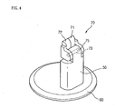
- FIG. 4 is a perspective view of an alternate embodiment of a supporting unit of a stand for a height adjusting structure of a display device
- FIG. 5 is an exploded perspective view of a vertical moving assembly of a height adjusting structure
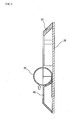
- FIG. 6 is a sectional view of the vertical moving assembly in FIG. 5 in an assembled state, taken along line I-I' ;
- FIG. 7 is a perspective view of the vertical moving assembly in FIG. 5 in an assembled state, taken along line II-II'.
- the height adjusting structure for a display device includes a vertical moving assembly 10 fixed to a rear surface 2 of the display device 1, a supporting unit 50 for supporting the vertical moving assembly 10, and a base unit 60 for resting on a horizontal surface and supporting the supporting unit 50 on the horizontal surface.
- the vertical moving assembly 10 includes a guide rail 20 fixed in a vertical direction to the lower portion of the rear surface 2, a guide unit 40 moving in a vertical direction within the guide rail 20, and a plate spring 30 formed between the guide rail 20 and guide unit 40, that expands and contracts according to the movement of the guide unit 40.
- the outer side of the guide unit is fixed to the upper portion of the supporting unit 50.
- the guide rail 20 and the guide unit 40 may be formed of a plastic material.
- the main body of the display device 1 When a user wishes to move the display device 1 in a vertical direction, the main body of the display device 1 is moved vertically.
- the guide unit 40 fixed to the supporting unit 50 moves along the guide rail 20.
- the plate spring 30 located at the top of the guide unit 40 is either elongated or contracted by the guide unit 40.
- the guide unit 40 stops moving, and the expanding or contracting plate spring 30 stops moving as a result.
- the plate spring 30 provides elasticity for supporting the weight of the display device 1 at the position that the plate spring 30 stops moving, so that the cessation of movement of the plate spring 30 stops the movement of the display device 1.
- the plate spring 30 may be provided with a spiral spring having a portion fixed to the display device and other portion coming in contact with the guide unit 40, so that the spiral spring may be expanded or contracted by a movement of the guide unit 40.
- the display device 1 may be moved up and down.
- the height adjusting structure of the display device 1 has the vertical moving assembly 10 fixed to the rear surface 2 thereof.
- the guide rail 20 of the vertical moving assembly 10 is fixed to the rear surface 2 of the display device 1, and the guide unit 40 moving along the guide rail 20 is fixed to the supporting unit 50. Accordingly, the center of gravity of the main body of the display device 1 is formed in proximity to the supporting unit 50. Therefore the stability preventing from the falling of the display device can be enhanced.
- the height adjusting structure for the display device is formed of plastic, so that the height adjusting structure itself forms the outer structure of the display device, negating the need for a separate component for covering the height adjusting structure.
- FIG. 3 is a perspective view showing an inner surface of a supporting unit for supporting a height adjusting structure according to the present embodiment.
- the supporting unit 50 includes a supporting stand 51 fixed to the base unit 60 resting on a horizontal surface, for supporting the display device 1 on the horizontal surface.
- a spring receptacle 54 is formed at the upper portion of the supporting stand 51, in which the top of the plate spring 30 protrudes outward from the vertical moving assembly 10, is disposed.
- One or more coupling protrusion(s) 58 are formed below the spring receptacle 54 for fastening the outer surface of the guide unit 40 on the supporting unit 50.
- the coupling protrusions 58 are coupled to coupling holes 49 (in FIG. 5 ) formed in the outer surface of the guide unit 40, so that the supporting stand 51 is coupled to the guide unit 40. Accordingly, the supporting unit 50 is connected to the vertical moving assembly 10 without using separate screws or other fasteners.
- the supporting unit 50 is formed to be fixed to the guide unit 40 of the vertical moving assembly 10 formed on the rear surface 2 of the display device 1, so that the guide unit 40 can move along the guide rail 20 when the display device 1 is moved vertically.
- the above supporting unit 50 may include a hinge unit at its top end that not only allows the display device to be moved vertically, but to also be pivoted upward and downward.
- FIG. 4 shows another embodiment of the supporting unit 50 with such a hinge unit formed thereon.
- a hinge unit 70 is provided at the top of the supporting unit 50.
- the hinge unit 70 has pivoting members 71 and 72 and a pivoting center portion 75.
- a pair of pivoting members 71 and 72 is pivotably installed on the outer surface of the guide unit 40.
- the guide unit 40 is fixed to one side of the pivoting members 71 and 72, and a hinge axis 73 is coupled with the other side thereof. Accordingly, the pivoting members 71 and 72 are formed to pivot around the pivoting center portion 75 formed at above the supporting stand 51.
- the display device 1, fixed to a side of the pivoting members 71 and 72, can be pivoted up and down around the central pivoting center portion 75.
- the stand of the display device can be adjusted in height and tilted up and down.
- the supporting unit may be formed to be capable of pivoting to the left and right as well as up and down.
- FIG. 5 is an exploded perspective view of a vertical moving assembly 10 of a height adjusting structure
- FIG. 6 is a sectional view of the vertical moving assembly 10 in FIG. 5 in an assembled state, taken along line I-I'
- FIG. 7 is a perspective view of the vertical moving assembly 10 in FIG. 5 in an assembled state, taken along line II-II'.
- the height adjusting structure includes a guide rail 20 formed vertically along the rear surface 2 of the display device 1 and a guide unit body 42 that moves vertically within and along the guide rail 20.
- the guide rail 20 is coupled to a rear surface fixing unit 11 fixed to the rear surface 2 of the display device 1, and is thus fixed to the rear surface 2 of the display device 1.
- an elastic member 30 is fixed to the inner surface of the rear surface fixing unit 11.
- the elastic member used is a plate spring 30, for example spiral spring.
- the plate spring is positioned to be expanded and contracted by the guide unit body 42.
- the guide rail 20 includes a pair of rails 21 disposed vertically on the rear surface 2 of the display device 1 and an upper section 23 formed at the top of the rails 21 for restricting the upper limit of the guide rail.
- the lower end of the guide rail 20 is open. Because the guide rail 20 is closed at the top and open at the bottom, it forms an inverted 'u' shape. The reason for the open bottom end is to provide space for some portion of the guide unit to reside.
- Each of the pair of rails 21 has a guide surface 22 on its inner side that contacts the side surfaces of the guide unit 40 and is vertically disposed against the rear surface 2 of the display device 1.
- the lower portion at the rear of the guide surface 22 does not contact the rear surface fixing unit 11, but is spaced a predetermined distance therefrom.
- Inclined surfaces 48 having a predetermined incline are formed on the sides of the guide unit body 42 between the lower end of the guide surface 22 and the rear surface fixing unit 11, for helping to guide the guide unit body 42 along the guide rail 20.
- a rail support 24 (refer to Fig. 7 ) is formed parallel to the inclined surface within the guide rail 20.
- the guide rail support 24 acts as a skeleton for supporting the rails 21 when the rails 21 are made of plastic.
- the width between the rails 21 is wider at the portion contacting the rear surface than at the top, recessing outward towards the bottom, as shown in FIG. 7 . This is so that the rails 21 form an outer portion of the display device 1 in order to refine the outer appearance of the rails 21.
- Coupling protrusions 26 are formed along the length of the guide rail 20 on the inner surface of the rails 21. These coupling protrusions 26 couple to guide rail fastening holes 29 formed on the rear surface fixing unit 11, to fix the guide rail 20 to the rear surface fixing unit 11.
- the rear surface fixing unit 11 is a component that fixes to the rear surface 2 of the display device 1, and is shaped in rectangular plate configuration.
- a plurality of fastening holes 29 are formed in the inner side of the rear surface fixing unit 11, for coupling with the coupling protrusions 26 of the rails 21.
- a side of the plate spring 30 is fixed to a spring mount 32 at the lower inner portion of the rear surface fixing unit 11.
- the spring mount 32 may be formed of an adhesive or other bonding material. Also, the spring mount 32 may take any other form as a structure that is able to fix one side of the plate spring to the rear surface fixing unit.
- the rear surface fixing unit may be omitted. That is, the plate spring and guide rail may all be directly fixed to the rear surface of the display device.
- the vertical moving assembly can be formed as a single operating component, so that it can be fixed to a variety of rear surface shapes of display devices.
- the plate spring 30, that is the elastic member, is a spiral spring that is wound. When the display device is raised, the wound spring is unwound; and when the display device is lowered, the wound spring is recoiled. Different from a tension spring that imparts elastic force when stretched, the plate spring imparts a constant elastic force whatever its position.
- One end of the plate spring 30 is fixed to the inner surface of the guide rail 20, and the other end extends along the guide rail 20.
- the elasticity of the extending plate spring is used to support the weight of the display device, so that the plate spring exerts the same elasticity for supporting the display device, regardless of the spring's extended position. Therefore, a separate stopping device is not required for the plate spring to come to a rest at whatever height the display device is positioned.
- a spring operating in this way can be called a coil-type plate spring.
- a guide unit 40 is disposed within the guide rail 20 for moving vertically along the guide rail 20.
- the guide unit 40 includes a spring guide 46 extending upward from either side of the guide unit body 42, and an inclined surface 48 protruding outward from either side of the guide unit body 42 at a slant and disposed within the guide rail 20.
- the guide unit 40 moves up and down along the guide rail 20, and acts as a pusher that pushes and extends the plate spring 30 disposed below it.
- the upper portion of the spring body as shown in FIG. 6 , has a convex-shaped spring pushing portion 44 formed thereon to contact and push the lower portion of the plate spring 30 upward.
- the spring pushing portion 44 may be formed in the same width as the plate spring 30 or have a wider width.
- a pair of spring guides 46 extends upward from the guide unit body 42 on either side of the spring pushing portion 44.
- the plate spring 30 is disposed between the pair of spring guides 46.
- the protruding length of the spring guides 46 may be roughly equal to the diameter of the plate spring 30.
- the spring guides 46 guide the sides of the plate spring 30 during compression and expansion of the plate spring 30.
- the inclined surface 48 is formed on either side of the guide unit body 42.
- the inclined surface 48 protrude in a decline from the centers of the side portions downward.
- the side surfaces 43 of the guide unit body 42 contacts the guide surfaces 22 of the guide rail 20.
- the inclined surfaces 48 at the bottom portions of the side surfaces 43 are located below the guide surfaces 22 of the guide rail 20. Therefore, when the guide rail 20 is erected in an upright position, and the guide unit body 42 moves vertically along the guide rail 20, the guide unit body 42 is prevented from being displaced outside the guide rail 20.
- the lower portions of the guide surfaces 48 are formed to catch on the inside of the guide rail 20.
- the guide unit body 42 is installed in the rails 21, it is prevented from escaping out from the rails 21.
- Coupling holes 49 are formed on the outer, upper surface of the guide unit body 42 to couple with coupling protrusions 58.
- the coupling protrusions 58 on the supporting unit 50 are inserted and coupled in the coupling holes 49, in order to couple the guide unit body 42 to the supporting unit 50.
- plastic rails and a plastic guide unit, and a plate spring fixed between the guide rail and the guide unit make up a minimum of components.
- noise caused by the plate spring contacting the guide unit can be reduced, and noise of the overall structure is reduced during its operation, while its operation is reliably performed.
- assembly of the rails and the guide unit does not require separate screws, and is easily performed by coupling the plastic protrusions and holes.
- the height adjusting structure has the display device 1 at its highest position when the guide unit body 42 is disposed at the lower portion of the rails 21.
- the body of the display device 1 is pushed downward.
- the guide unit body 42 moves up along the guide rail 20
- the guide unit body 42 pushes the plate spring 30 upward.
- the plate spring 30 is pushed upward, the guide unit body 42 rises, and the display device 1 body descends.
- the display device 1 comes to a standstill at the position where it was released.
- the height of the display device can be adjusted in a range corresponding to the height of the guide rail installed on the display device.
- the above height adjusting structure for a display device allows a simple assembly using few components.
- the height adjusting structure for a display device does not use screws as fasteners, so that the structure is more resistant to external shocks.
- the stand puts the center of gravity of the display device close to the supporting unit, the display device can be more securely supported.
- the respective components forming the height adjusting structure are made of plastic, noise during operation of the structure is reduced and operational reliability is increased.
Landscapes
- Engineering & Computer Science (AREA)
- General Engineering & Computer Science (AREA)
- Mechanical Engineering (AREA)
- Theoretical Computer Science (AREA)
- Computer Hardware Design (AREA)
- Human Computer Interaction (AREA)
- Physics & Mathematics (AREA)
- General Physics & Mathematics (AREA)
- Multimedia (AREA)
- Signal Processing (AREA)
- Devices For Indicating Variable Information By Combining Individual Elements (AREA)
Claims (10)
- Ständer für eine Anzeigevorrichtung, mit:einer Rückflächen-Fixiereinheit (11), die an der Rückfläche einer Anzeigevorrichtung (1) fixierbar ist,einem elastischen Element (30), das mit einem seiner Enden an der Rückflächen-Fixiereinheit (11) fixiert ist,einer Führungsschiene (20), die auf der Rückfläche der Rückflächen-Fixiereinheit (11) vertikal angeordnet ist,einen auf einer Tragfläche getragenen Sockel (60),einer Trageinheit (50), die sich vom Sockel (60) aufwärts erstreckt, undeiner Führungseinheit (40), die mit der Trageinheit (50) verbunden ist, um ein anderes Ende des elastischen Elements (30) zu berühren und das elastische Element (30) während der Höhenverstellung einer Anzeigevorrichtung (1) zu verkürzen und zu verlängern, wobei die Führungseinheit (40) von der Führungsschiene (20) geführt wird.
- Ständer nach Anspruch 1, wobei das elastische Element (30) eine Blattfeder ist.
- Ständer nach Anspruch 1, weiters mit einer Federbefestigung (32) zum Fixieren des einen Endes des elastischen Elements (30) an der Rückfläche der Fixiereinheit (11).
- Ständer nach Anspruch 1, wobei das elastische Element (30) eine rollenartige Blattfeder ist.
- Ständer nach Anspruch 1, wobei die Führungsschiene (20) an ihren Innenseiten gebildete Schienen (21) enthält, denen entlang die Führungseinheit (40) gleitet.
- Ständer nach Anspruch 1, wobei die Führungsschiene (20) aus Kunststoffmaterial hergestellt ist.
- Ständer nach Anspruch 1, wobei die Führungseinheit (40) aus Kunststoffmaterial hergestellt ist.
- Ständer nach einem der vorherigen Ansprüche, weiters mit einer Gelenkeinheit (70), die zwischen der Trageinheit (50) und der Führungseinheit (40) angeordnet ist, um ein Schwenken einer Anzeigevorrichtung (1) zu ermöglichen.
- Ständer nach einem der vorherigen Ansprüche, wobei sich das elastische Element (30) verlängert, wenn die Höhe einer Anzeigevorrichtung niedrig ist, und wobei sich das elastische Element (30) verkürzt, wenn die Höhe einer Anzeigevorrichtung groß ist.
- Ständer nach einem der vorherigen Ansprüche, wobei die Führungsschiene (20), die Führungseinheit (40) und die Trageinheit (50) aus Kunststoffmaterial hergestellt sind.
Applications Claiming Priority (1)
| Application Number | Priority Date | Filing Date | Title |
|---|---|---|---|
| KR1020050104424A KR100767845B1 (ko) | 2005-11-02 | 2005-11-02 | 영상 디스플레이 기기의 높낮이 조절 구조 |
Publications (3)
| Publication Number | Publication Date |
|---|---|
| EP1783419A2 EP1783419A2 (de) | 2007-05-09 |
| EP1783419A3 EP1783419A3 (de) | 2008-01-02 |
| EP1783419B1 true EP1783419B1 (de) | 2009-09-30 |
Family
ID=37691741
Family Applications (1)
| Application Number | Title | Priority Date | Filing Date |
|---|---|---|---|
| EP06254439A Expired - Fee Related EP1783419B1 (de) | 2005-11-02 | 2006-08-24 | Höhenverstellvorrichtung einer Anzeigevorrichtung und Ständer für eine Anzeigevorrichtung |
Country Status (5)
| Country | Link |
|---|---|
| US (1) | US7690620B2 (de) |
| EP (1) | EP1783419B1 (de) |
| KR (1) | KR100767845B1 (de) |
| CN (1) | CN1959852A (de) |
| DE (1) | DE602006009456D1 (de) |
Families Citing this family (11)
| Publication number | Priority date | Publication date | Assignee | Title |
|---|---|---|---|---|
| KR100710314B1 (ko) * | 2006-06-01 | 2007-04-23 | 엘지전자 주식회사 | 모니터 스탠드 |
| CN101660650B (zh) * | 2008-08-26 | 2012-03-28 | 鸿富锦精密工业(深圳)有限公司 | 支撑机构及采用该支撑机构的电子装置 |
| JP4923121B2 (ja) * | 2010-02-25 | 2012-04-25 | 東芝テック株式会社 | ディスプレイ装置及びディスプレイ装置システム |
| US9103490B2 (en) * | 2010-04-21 | 2015-08-11 | Hewlett-Packard Development Company, L.P. | Chassis, base, and negator spring |
| USD650372S1 (en) * | 2011-06-01 | 2011-12-13 | Peerless Industries, Inc. | Surface top mounting system for use with audio/visual devices or the like |
| CN103782249B (zh) | 2011-09-09 | 2018-08-17 | 惠普发展公司,有限责任合伙企业 | 可调节显示监视器支架 |
| US10132442B2 (en) * | 2015-07-17 | 2018-11-20 | Crestron Electronics, Inc. | Constant friction rotating monitor stand |
| CN109345971B (zh) | 2018-12-21 | 2021-04-20 | 苏州佳世达电通有限公司 | 显示设备及其高度调整机构 |
| CN110469757A (zh) * | 2019-09-11 | 2019-11-19 | 韩勇 | 一种可视化交互式临床随访的系统 |
| CN114867963A (zh) | 2019-11-27 | 2022-08-05 | 德康有限公司 | 姿势矫正用显示器安装装置以及利用其的显示器安装控制系统 |
| WO2026014219A1 (ja) * | 2024-07-12 | 2026-01-15 | ソニーグループ株式会社 | 表示装置 |
Family Cites Families (14)
| Publication number | Priority date | Publication date | Assignee | Title |
|---|---|---|---|---|
| KR200279427Y1 (ko) | 2002-03-12 | 2002-06-24 | 피케이텍시스템 주식회사 | 액정 모니터의 승강장치 |
| AUPS285202A0 (en) | 2002-06-07 | 2002-06-27 | Claiteal Pty Ltd | Stand for flat panel display |
| TW532735U (en) * | 2002-06-25 | 2003-05-11 | Benq Corp | Height adjustable apparatus for supporting flat monitor |
| US6702238B1 (en) * | 2003-03-28 | 2004-03-09 | Top Victory Electronics Co., Ltd. | Adjustable supporting device for a display panel |
| US6712321B1 (en) * | 2003-05-21 | 2004-03-30 | Compal Electronics, Inc. | Adjustable supporting device for a display panel |
| TWI273877B (en) | 2003-10-30 | 2007-02-11 | Quanta Comp Inc | Rail structure |
| TWI228372B (en) * | 2003-10-30 | 2005-02-21 | Quanta Comp Inc | Plastic adjustable pedestal |
| JP4402448B2 (ja) * | 2003-12-24 | 2010-01-20 | 株式会社新鋭産業 | ディスプレイモニター用スタンド |
| US20050184215A1 (en) * | 2004-02-19 | 2005-08-25 | Lin Yu-Sen | Spiral spring for a liquid crystal display stand |
| KR100531314B1 (ko) | 2004-03-16 | 2005-11-29 | 엘지전자 주식회사 | 영상표시장치 |
| USD504426S1 (en) * | 2004-06-08 | 2005-04-26 | Flextronics International Usa, Inc. | Desktop computer |
| US7036787B1 (en) * | 2005-02-04 | 2006-05-02 | Taiwan Thick-Film Ind. Corp. | Display strut adjusting structure |
| KR100682670B1 (ko) * | 2005-11-02 | 2007-02-15 | 엘지전자 주식회사 | 힌지 구조 및 상기 힌지 구조를 사용한 스탠드 |
| KR100846898B1 (ko) * | 2005-12-30 | 2008-07-17 | 엘지전자 주식회사 | 영상 디스플레이 기기의 스탠드 |
-
2005
- 2005-11-02 KR KR1020050104424A patent/KR100767845B1/ko not_active Expired - Fee Related
-
2006
- 2006-07-11 US US11/483,544 patent/US7690620B2/en active Active
- 2006-07-28 CN CNA2006101086679A patent/CN1959852A/zh active Pending
- 2006-08-24 EP EP06254439A patent/EP1783419B1/de not_active Expired - Fee Related
- 2006-08-24 DE DE602006009456T patent/DE602006009456D1/de active Active
Also Published As
| Publication number | Publication date |
|---|---|
| EP1783419A3 (de) | 2008-01-02 |
| DE602006009456D1 (de) | 2009-11-12 |
| EP1783419A2 (de) | 2007-05-09 |
| KR100767845B1 (ko) | 2007-10-17 |
| CN1959852A (zh) | 2007-05-09 |
| US7690620B2 (en) | 2010-04-06 |
| US20070096001A1 (en) | 2007-05-03 |
Similar Documents
| Publication | Publication Date | Title |
|---|---|---|
| US7694919B2 (en) | Stand for display device | |
| US20070205340A1 (en) | Supporting device for display units | |
| EP1803987B1 (de) | Ständer für eine Anzeigevorrichtung | |
| US7458546B2 (en) | Monitor stand | |
| US6905099B2 (en) | Monitor | |
| US7690620B2 (en) | Height adjusting device of a display device and stand for display device | |
| US7293747B2 (en) | Display moveable in two dimensions | |
| US20070278362A1 (en) | Monitor stand | |
| CN101601285A (zh) | 用于显示设备的支撑装置 | |
| US8256733B2 (en) | Support mechanism | |
| US20100320339A1 (en) | Height adjustable stand and flat panel display utilizing the same | |
| US20190293229A1 (en) | Monitor stand | |
| CN102065726A (zh) | 用于抽屉滑动装置的控制机构 | |
| JP6625097B2 (ja) | スライドシステム及びスライドシステムに用いられる調整アセンブリ | |
| US20050109894A1 (en) | Plastic pedestal with a height adjustment function | |
| EP2184641B1 (de) | Projektorähnliche Bildanzeigevorrichtung | |
| CN106766620A (zh) | 冰箱及其瓶座 | |
| TW202342913A (zh) | 顯示器支架及其顯示裝置 | |
| JP3748613B2 (ja) | 収納部昇降支持装置 | |
| KR100765242B1 (ko) | 평판형 tv용 벽걸이식 거치대 | |
| US7409271B2 (en) | Electronic device with height adjusting mechanism | |
| JP2018204209A (ja) | 扉体開閉装置並びにこの扉体開閉装置を備えた各種キャビネット | |
| CN114754542B (zh) | 可调搁物架装置及具有其的冰箱 | |
| JP2843312B2 (ja) | 棚載置物落下防止装置 | |
| JP2000217642A (ja) | 机等における配線ダクト装置 |
Legal Events
| Date | Code | Title | Description |
|---|---|---|---|
| PUAI | Public reference made under article 153(3) epc to a published international application that has entered the european phase |
Free format text: ORIGINAL CODE: 0009012 |
|
| 17P | Request for examination filed |
Effective date: 20060920 |
|
| AK | Designated contracting states |
Kind code of ref document: A2 Designated state(s): AT BE BG CH CY CZ DE DK EE ES FI FR GB GR HU IE IS IT LI LT LU LV MC NL PL PT RO SE SI SK TR |
|
| AX | Request for extension of the european patent |
Extension state: AL BA HR MK YU |
|
| PUAL | Search report despatched |
Free format text: ORIGINAL CODE: 0009013 |
|
| AK | Designated contracting states |
Kind code of ref document: A3 Designated state(s): AT BE BG CH CY CZ DE DK EE ES FI FR GB GR HU IE IS IT LI LT LU LV MC NL PL PT RO SE SI SK TR |
|
| AX | Request for extension of the european patent |
Extension state: AL BA HR MK YU |
|
| 17Q | First examination report despatched |
Effective date: 20080722 |
|
| AKX | Designation fees paid |
Designated state(s): DE FR GB |
|
| GRAP | Despatch of communication of intention to grant a patent |
Free format text: ORIGINAL CODE: EPIDOSNIGR1 |
|
| GRAS | Grant fee paid |
Free format text: ORIGINAL CODE: EPIDOSNIGR3 |
|
| GRAA | (expected) grant |
Free format text: ORIGINAL CODE: 0009210 |
|
| AK | Designated contracting states |
Kind code of ref document: B1 Designated state(s): DE FR GB |
|
| REG | Reference to a national code |
Ref country code: GB Ref legal event code: FG4D |
|
| REF | Corresponds to: |
Ref document number: 602006009456 Country of ref document: DE Date of ref document: 20091112 Kind code of ref document: P |
|
| PLBE | No opposition filed within time limit |
Free format text: ORIGINAL CODE: 0009261 |
|
| STAA | Information on the status of an ep patent application or granted ep patent |
Free format text: STATUS: NO OPPOSITION FILED WITHIN TIME LIMIT |
|
| 26N | No opposition filed |
Effective date: 20100701 |
|
| REG | Reference to a national code |
Ref country code: FR Ref legal event code: ST Effective date: 20110502 |
|
| REG | Reference to a national code |
Ref country code: DE Ref legal event code: R119 Ref document number: 602006009456 Country of ref document: DE Effective date: 20110301 |
|
| PG25 | Lapsed in a contracting state [announced via postgrant information from national office to epo] |
Ref country code: FR Free format text: LAPSE BECAUSE OF NON-PAYMENT OF DUE FEES Effective date: 20100831 Ref country code: DE Free format text: LAPSE BECAUSE OF NON-PAYMENT OF DUE FEES Effective date: 20110301 |
|
| PGFP | Annual fee paid to national office [announced via postgrant information from national office to epo] |
Ref country code: GB Payment date: 20190708 Year of fee payment: 14 |
|
| GBPC | Gb: european patent ceased through non-payment of renewal fee |
Effective date: 20200824 |
|
| PG25 | Lapsed in a contracting state [announced via postgrant information from national office to epo] |
Ref country code: GB Free format text: LAPSE BECAUSE OF NON-PAYMENT OF DUE FEES Effective date: 20200824 |