EP1783579A2 - Fahrpedal mit Halleffekt-Bewegungssensor - Google Patents
Fahrpedal mit Halleffekt-Bewegungssensor Download PDFInfo
- Publication number
- EP1783579A2 EP1783579A2 EP06123507A EP06123507A EP1783579A2 EP 1783579 A2 EP1783579 A2 EP 1783579A2 EP 06123507 A EP06123507 A EP 06123507A EP 06123507 A EP06123507 A EP 06123507A EP 1783579 A2 EP1783579 A2 EP 1783579A2
- Authority
- EP
- European Patent Office
- Prior art keywords
- hall
- pedal
- effect sensor
- fixed base
- magnet
- Prior art date
- Legal status (The legal status is an assumption and is not a legal conclusion. Google has not performed a legal analysis and makes no representation as to the accuracy of the status listed.)
- Withdrawn
Links
Images
Classifications
-
- B—PERFORMING OPERATIONS; TRANSPORTING
- B60—VEHICLES IN GENERAL
- B60K—ARRANGEMENT OR MOUNTING OF PROPULSION UNITS OR OF TRANSMISSIONS IN VEHICLES; ARRANGEMENT OR MOUNTING OF PLURAL DIVERSE PRIME-MOVERS IN VEHICLES; AUXILIARY DRIVES FOR VEHICLES; INSTRUMENTATION OR DASHBOARDS FOR VEHICLES; ARRANGEMENTS IN CONNECTION WITH COOLING, AIR INTAKE, GAS EXHAUST OR FUEL SUPPLY OF PROPULSION UNITS IN VEHICLES
- B60K26/00—Arrangement or mounting of propulsion-unit control devices in vehicles
- B60K26/02—Arrangement or mounting of propulsion-unit control devices in vehicles of initiating means or elements
-
- G—PHYSICS
- G05—CONTROLLING; REGULATING
- G05G—CONTROL DEVICES OR SYSTEMS INSOFAR AS CHARACTERISED BY MECHANICAL FEATURES ONLY
- G05G1/00—Controlling members, e.g. knobs or handles; Assemblies or arrangements thereof; Indicating position of controlling members
- G05G1/30—Controlling members actuated by foot
- G05G1/38—Controlling members actuated by foot comprising means to continuously detect pedal position
-
- B—PERFORMING OPERATIONS; TRANSPORTING
- B60—VEHICLES IN GENERAL
- B60W—CONJOINT CONTROL OF VEHICLE SUB-UNITS OF DIFFERENT TYPE OR DIFFERENT FUNCTION; CONTROL SYSTEMS SPECIALLY ADAPTED FOR HYBRID VEHICLES; ROAD VEHICLE DRIVE CONTROL SYSTEMS FOR PURPOSES NOT RELATED TO THE CONTROL OF A PARTICULAR SUB-UNIT
- B60W2420/00—Indexing codes relating to the type of sensors based on the principle of their operation
- B60W2420/50—Magnetic or electromagnetic sensors
- B60W2420/503—Hall effect or magnetoresistive, i.e. active wheel speed sensors
Definitions
- the present invention concerns an accelerator pedal with Hall-effect movement sensor.
- a type of pedal is increasingly gaining a foothold in which the position of the pedal itself, and therefore the acceleration required is detected by a sensor which outputs an electrical signal linearly varying in accordance with the position of the pedal.
- accelerator pedals on sale consisting of a movable lever, rotatably coupled by means of a pin to a cylindrical housing which is integral with a fixed base.
- potentiometers or rotary sensors entails friction and rolling which are a cause of premature wear of the mechanical components and therefore of unreliability.
- the measurement is not very accurate, especially with the passage of time, precisely because of the above-mentioned premature wear of the mechanical components.
- the object of the present invention is to produce a pedal for vehicles including a device for detecting movement which is of simple and reliable construction.
- a pedal for the control of vehicles including a movable lever rotatably coupled to a fixed base, and a device for detecting the movement of said movable lever with respect to said fixed base, characterised in that said device comprises a magnet capable of interacting with a Hall-effect sensor, and a circuit board for the processing and transmission of the information detected by said Hall-effect sensor.
- the magnet and the Hall-effect sensor are static elements spaced apart from each other, and for this reason there is no friction or rolling between mechanical components
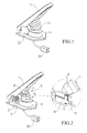
- the pedal shown in figures 1-3 in particular an accelerator pedal, includes a movable lever 1 rotatably coupled by means of a horizontal pin 2 to a cylindrical housing 3 on a fixed base 4, an electrical connector plug 20 and a device 5 for detecting movement, covered by a sleeve 13.
- Said device 5 includes a movable magnet 6 (made up of ferrite, for example), made integral with lever 1 by a support element 7, and capable of interacting with a Hall-effect sensor 8 fixed to base 4 by means of a support body 9.
- a movable magnet 6 made up of ferrite, for example
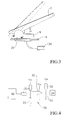
- Figure 4 shows a schematic representation of said circuit board including a main block 40 representing the portion of the circuit usable for the reception and processing of the signal coming from sensor 8, and an amplification circuit 30 including resistances 31, an amplifier 32, a condenser 33, feeds of various voltages and earths.
- the output signal, proportional to the angle "swept" by lever 1, is represented by a block 34.
- said circuit board includes means to allow it to be adequately tolerant of automotive electrical conditions such as positive and negative peaks which are particularly destructive and not suitably filtered or eliminated. It is also completely encased in resin to prevent electromagnetic interferences and emissions, in accordance with EU regulations.
- pressing lever 1 causes the latter to rotate, and thus also causes the rotation of magnet 6.
- Sensor 8 thus begins to interact with the magnetic field induced by the ferrite magnet 6.
- the pedal specifically a microprocessor integrated into the board, will provide an analogue output at a proportional voltage, which the amplification circuit 30 proceeds to amplify.
- the lever can be preset to rotate through a maximum angle (for example 22°), which will correspond to the maximum output voltage.
- Block 40 is therefore equipped with a microprocessor with a programmable memory.
- Each pedal is calibrated and tested individually through a computerised process which allows the analogue output to be set in accordance with the angle "swept" by lever 1.
- the mechanical part (lever 1, base 4, pin 2 etc) is made with pressing equipment which guarantees a working life of ten million operations, thanks also to further hardening and anti-corrosion treatment.
Landscapes
- Engineering & Computer Science (AREA)
- Physics & Mathematics (AREA)
- General Physics & Mathematics (AREA)
- Automation & Control Theory (AREA)
- Chemical & Material Sciences (AREA)
- Combustion & Propulsion (AREA)
- Transportation (AREA)
- Mechanical Engineering (AREA)
- Mechanical Control Devices (AREA)
- Transmission And Conversion Of Sensor Element Output (AREA)
- Control Of Throttle Valves Provided In The Intake System Or In The Exhaust System (AREA)
Applications Claiming Priority (1)
| Application Number | Priority Date | Filing Date | Title |
|---|---|---|---|
| IT002121A ITMI20052121A1 (it) | 2005-11-08 | 2005-11-08 | Pedale acceleratore con sensore di movimento e effetto hall |
Publications (2)
| Publication Number | Publication Date |
|---|---|
| EP1783579A2 true EP1783579A2 (de) | 2007-05-09 |
| EP1783579A3 EP1783579A3 (de) | 2007-10-31 |
Family
ID=37744287
Family Applications (1)
| Application Number | Title | Priority Date | Filing Date |
|---|---|---|---|
| EP06123507A Withdrawn EP1783579A3 (de) | 2005-11-08 | 2006-11-06 | Fahrpedal mit Halleffekt-Bewegungssensor |
Country Status (3)
| Country | Link |
|---|---|
| US (1) | US20070103148A1 (de) |
| EP (1) | EP1783579A3 (de) |
| IT (1) | ITMI20052121A1 (de) |
Families Citing this family (6)
| Publication number | Priority date | Publication date | Assignee | Title |
|---|---|---|---|---|
| US8635930B2 (en) * | 2007-06-22 | 2014-01-28 | Ksr Technologies Co. | Floor mounted pedal with position sensor |
| DE102010028618A1 (de) * | 2010-05-05 | 2011-11-10 | Zf Friedrichshafen Ag | Fahrpedal |
| KR101447806B1 (ko) * | 2013-02-28 | 2014-10-13 | 대성전기공업 주식회사 | 비접촉 브레이크 스위치 |
| KR102064565B1 (ko) * | 2014-11-11 | 2020-02-11 | 현대자동차(주) | 차량용 오르간 타입 가속페달 장치 |
| JP6672088B2 (ja) * | 2016-06-21 | 2020-03-25 | 株式会社クボタ | 作業機 |
| JP2024133862A (ja) * | 2023-03-20 | 2024-10-03 | 株式会社東海理化電機製作所 | ストローク信号出力装置 |
Family Cites Families (5)
| Publication number | Priority date | Publication date | Assignee | Title |
|---|---|---|---|---|
| DE19828533C2 (de) * | 1998-06-26 | 2000-12-14 | Harting Kgaa | Erfassung von Pedalstellungen |
| DE10009168A1 (de) * | 2000-02-26 | 2001-09-13 | Bosch Gmbh Robert | Messvorrichtung und Verfahren zur Erfassung einer Kraft |
| US6802202B2 (en) * | 2001-07-27 | 2004-10-12 | Denso Corporation | Method for adjusting accelerator pedal apparatus |
| EP1420974B1 (de) * | 2001-08-31 | 2005-01-19 | Siemens Aktiengesellschaft | Verschleissfreier fahrpedal-kick-down-schalter |
| JP2003148908A (ja) * | 2001-11-14 | 2003-05-21 | Hitachi Unisia Automotive Ltd | アクセル操作量検出装置 |
-
2005
- 2005-11-08 IT IT002121A patent/ITMI20052121A1/it unknown
-
2006
- 2006-11-06 US US11/593,253 patent/US20070103148A1/en not_active Abandoned
- 2006-11-06 EP EP06123507A patent/EP1783579A3/de not_active Withdrawn
Also Published As
| Publication number | Publication date |
|---|---|
| US20070103148A1 (en) | 2007-05-10 |
| ITMI20052121A1 (it) | 2007-05-09 |
| EP1783579A3 (de) | 2007-10-31 |
Similar Documents
| Publication | Publication Date | Title |
|---|---|---|
| US7439732B2 (en) | Rotary position sensor | |
| US6175233B1 (en) | Two axis position sensor using sloped magnets to generate a variable magnetic field and hall effect sensors to detect the variable magnetic field | |
| US20160069709A1 (en) | Magnetic Field Sensor Apparatus, Operating Apparatus and Method for Determining a Relative Position | |
| WO2004033994A1 (en) | Angular position sensor | |
| EP0844487A3 (de) | Magnetische Fühler | |
| GB2131554A (en) | Electronic position transmitter | |
| EP1783579A2 (de) | Fahrpedal mit Halleffekt-Bewegungssensor | |
| EP1806845B1 (de) | Kontaktloser Positionssensor mit reversibler Selbsteinstellung | |
| US20190271570A1 (en) | Integrated dual rotary position sensor | |
| US7668677B2 (en) | Error correction method for a displacement sensor signal | |
| CN114270132A (zh) | 用于捕获可旋转轴的扭矩和角度位置的传感器组件 | |
| PT2222984E (pt) | Sensor de posição de uma caixa de velocidades e caixa de velocidades correspondente | |
| US6104592A (en) | Electromechanical switching device | |
| US11391557B2 (en) | Magnetic angular position sensor circuit | |
| US6989670B2 (en) | Device for measuring paths and/or positions | |
| JP2004230169A (ja) | 安全スキービンディング | |
| DE102005056632A1 (de) | Pedalpositionssensor mit Redundanz | |
| AU2002358621A1 (en) | Contactless sensing input device | |
| US7219562B2 (en) | Angle sensor | |
| CN204649213U (zh) | 手动脉冲发生装置 | |
| CN210441810U (zh) | 抗干扰磁场的位移传感器、马达组件以及变速箱 | |
| JP2002542472A (ja) | 測定装置 | |
| JPH0555007U (ja) | 歯車の回転検出センサ | |
| US8032283B2 (en) | Angle measuring apparatus for measuring an absolute angular position | |
| EP3516759B1 (de) | Drehpositionssensor mit doppelmagnetanordnung |
Legal Events
| Date | Code | Title | Description |
|---|---|---|---|
| PUAI | Public reference made under article 153(3) epc to a published international application that has entered the european phase |
Free format text: ORIGINAL CODE: 0009012 |
|
| AK | Designated contracting states |
Kind code of ref document: A2 Designated state(s): AT BE BG CH CY CZ DE DK EE ES FI FR GB GR HU IE IS IT LI LT LU LV MC NL PL PT RO SE SI SK TR |
|
| AX | Request for extension of the european patent |
Extension state: AL BA HR MK YU |
|
| PUAL | Search report despatched |
Free format text: ORIGINAL CODE: 0009013 |
|
| AK | Designated contracting states |
Kind code of ref document: A3 Designated state(s): AT BE BG CH CY CZ DE DK EE ES FI FR GB GR HU IE IS IT LI LT LU LV MC NL PL PT RO SE SI SK TR |
|
| AX | Request for extension of the european patent |
Extension state: AL BA HR MK YU |
|
| AKX | Designation fees paid | ||
| REG | Reference to a national code |
Ref country code: DE Ref legal event code: 8566 |
|
| STAA | Information on the status of an ep patent application or granted ep patent |
Free format text: STATUS: THE APPLICATION IS DEEMED TO BE WITHDRAWN |
|
| 18D | Application deemed to be withdrawn |
Effective date: 20080503 |