EP1783668A2 - Unité de transpondeur - Google Patents
Unité de transpondeur Download PDFInfo
- Publication number
- EP1783668A2 EP1783668A2 EP06019370A EP06019370A EP1783668A2 EP 1783668 A2 EP1783668 A2 EP 1783668A2 EP 06019370 A EP06019370 A EP 06019370A EP 06019370 A EP06019370 A EP 06019370A EP 1783668 A2 EP1783668 A2 EP 1783668A2
- Authority
- EP
- European Patent Office
- Prior art keywords
- transponder
- antenna
- housing
- transponder unit
- unit according
- Prior art date
- Legal status (The legal status is an assumption and is not a legal conclusion. Google has not performed a legal analysis and makes no representation as to the accuracy of the status listed.)
- Withdrawn
Links
Images



Classifications
-
- G—PHYSICS
- G06—COMPUTING OR CALCULATING; COUNTING
- G06K—GRAPHICAL DATA READING; PRESENTATION OF DATA; RECORD CARRIERS; HANDLING RECORD CARRIERS
- G06K19/00—Record carriers for use with machines and with at least a part designed to carry digital markings
- G06K19/06—Record carriers for use with machines and with at least a part designed to carry digital markings characterised by the kind of the digital marking, e.g. shape, nature, code
- G06K19/067—Record carriers with conductive marks, printed circuits or semiconductor circuit elements, e.g. credit or identity cards also with resonating or responding marks without active components
- G06K19/07—Record carriers with conductive marks, printed circuits or semiconductor circuit elements, e.g. credit or identity cards also with resonating or responding marks without active components with integrated circuit chips
- G06K19/077—Constructional details, e.g. mounting of circuits in the carrier
- G06K19/07749—Constructional details, e.g. mounting of circuits in the carrier the record carrier being capable of non-contact communication, e.g. constructional details of the antenna of a non-contact smart card
- G06K19/07773—Antenna details
- G06K19/07775—Antenna details the antenna being on-chip
-
- G—PHYSICS
- G06—COMPUTING OR CALCULATING; COUNTING
- G06K—GRAPHICAL DATA READING; PRESENTATION OF DATA; RECORD CARRIERS; HANDLING RECORD CARRIERS
- G06K19/00—Record carriers for use with machines and with at least a part designed to carry digital markings
- G06K19/06—Record carriers for use with machines and with at least a part designed to carry digital markings characterised by the kind of the digital marking, e.g. shape, nature, code
- G06K19/067—Record carriers with conductive marks, printed circuits or semiconductor circuit elements, e.g. credit or identity cards also with resonating or responding marks without active components
- G06K19/07—Record carriers with conductive marks, printed circuits or semiconductor circuit elements, e.g. credit or identity cards also with resonating or responding marks without active components with integrated circuit chips
- G06K19/077—Constructional details, e.g. mounting of circuits in the carrier
- G06K19/07749—Constructional details, e.g. mounting of circuits in the carrier the record carrier being capable of non-contact communication, e.g. constructional details of the antenna of a non-contact smart card
-
- G—PHYSICS
- G06—COMPUTING OR CALCULATING; COUNTING
- G06K—GRAPHICAL DATA READING; PRESENTATION OF DATA; RECORD CARRIERS; HANDLING RECORD CARRIERS
- G06K19/00—Record carriers for use with machines and with at least a part designed to carry digital markings
- G06K19/06—Record carriers for use with machines and with at least a part designed to carry digital markings characterised by the kind of the digital marking, e.g. shape, nature, code
- G06K19/067—Record carriers with conductive marks, printed circuits or semiconductor circuit elements, e.g. credit or identity cards also with resonating or responding marks without active components
- G06K19/07—Record carriers with conductive marks, printed circuits or semiconductor circuit elements, e.g. credit or identity cards also with resonating or responding marks without active components with integrated circuit chips
- G06K19/077—Constructional details, e.g. mounting of circuits in the carrier
- G06K19/07749—Constructional details, e.g. mounting of circuits in the carrier the record carrier being capable of non-contact communication, e.g. constructional details of the antenna of a non-contact smart card
- G06K19/07773—Antenna details
- G06K19/07777—Antenna details the antenna being of the inductive type
- G06K19/07779—Antenna details the antenna being of the inductive type the inductive antenna being a coil
Definitions
- the invention relates to a transponder unit in a hermetically sealed housing, comprising a housing lower part and a housing upper part.
- RFID Radio Frequency Identification Systems
- RFID systems consist of a transmission module (transponder) with stored data, wherein the transponder is formed of one or more integrated circuits (transponder ICs), an antenna and other passive components. Furthermore, the system requires a receiver module or a reader for data acquisition. The transponder is attached to the goods to be monitored. The distance between the transponder and the reader (read distance) depends on the transmission system and the frequency used. In Europe, RFID systems can be operated in the so-called SRD band between 868 and 870 MHz (now also 865 and 868 MHz) and worldwide between 2400 and 2483.5 MHz.
- the transponder In passive systems, the transponder is powered by a magnetic or electro-magnetic field. Due to the external power supply, the structure can be made very simple and inexpensive.
- transponder The scope of a transponder depends essentially on the reading distance and the characteristics of the housing. In order to enable the widest possible range of use, the housing should be as small as possible and insensitive to environmental influences. In addition, unrestricted functioning on conductive, absorbent or reflective surfaces must be ensured.
- transponder ICs can be contacted by soldering, micro welding or crimping. Transponder ICs without their own housing can be directly connected by gluing or soldering.
- the manufacturing process of a transponder can be subdivided into the following steps: Assembly and adjustment of the antenna and the transponder IC in the housing. Contacting of the transponder IC to the antenna and to the ground plane. Inserting a dielectric and closing the housing by screwing, gluing or welding.
- the disadvantage here is that assembly and adjustment errors affect the functionality and efficiency of the transponder. Furthermore, the stability and dimensional stability is not guaranteed with strong temperature changes and external mechanical stress with different materials joined together, because components with different properties be connected to each other. In addition, adaptations to changed external conditions are only possible through changes to the components, which in many cases require a new design.
- the invention is therefore based on the object to form a transponder of the type mentioned in that are excluded by the production of the conductor body, the antenna and the ground surface of a piece assembly and adjustment errors.
- the housing lower part is provided with a ground surface, and that an antenna is arranged at a distance from the ground surface.
- the antenna may be formed as a one-piece integrally formed on the housing base, spaced web on which a strip-shaped antenna is applied.
- the antenna can be integrated as a metallized strip in the upper side of the housing. Whereby advantageously no assembly and adjustment work of the antenna are necessary.
- the conductive metallized antenna strips in the upper part and the grid-like or flat ground plane in the lower part are produced by a selective metallization.
- the ground surface can be applied inside or outside the housing base.
- the stability of the housing and the emission characteristic of the transponder can be advantageously influenced.
- the design of the housing with appropriate mounting aids, such as holes, slots and positive surfaces for bonding, allows easy installation on any objects.
- the transponder is suitable for all mounting surfaces and can be used reliably even in industrial environments.
- a transponder unit 1 with a lower housing part 2 and an upper housing part 3 is shown.
- the upper housing part has mounting aids 8 in the form of holes and / or slots, which facilitate the attachment of the transponder on any objects.
- a ground surface 4 is provided, which consists of intersecting metal strips, so that a grid is formed. However, the ground surface can also be formed flat.
- the lower housing part 2 is inserted into a corresponding annular recess 10 in the upper housing part 3, and preferably welded, so that a seamless surface between the laterally projecting surfaces of the mounting aids 8 and the lower housing part 2 is formed.
- the inside of the upper housing part 3 of the transponder unit 1 is shown in a perspective view.
- Meander-shaped metallic strips form an antenna 5 on the convex inner side.
- the antenna is adhesive-free applied directly to the upper housing part, so that deformation under thermal or mechanical stress are significantly reduced and a long-term dimensional stability is guaranteed.
- the metallic strips of the antenna are not in one plane, but are adapted to the housing shape, so that there is an optimal use of the available area and a large margin for the design and the adjustment of the antenna.
- the transponder IC 7 is arranged approximately centrally in the housing upper side 3, the antenna 5 being supplied via a coupling loop 6 connected to the IC 7.
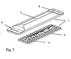
- FIG. 3 shows a transponder unit 1 with a housing lower part 2 and an upper housing part 3.
- the upper housing part has mounting aids 8 in the form of holes and / or slots, which facilitates the attachment of the transponder on any objects.
- the lower housing part 2 of the transponder unit 1 is shown in a perspective view.
- a web 11 is arranged with a plurality of spacer elements 12 on the lower housing part by means of a so-called casting process.
- an antenna 5 forming a metallic strip is applied on the web 11 .
- the lower housing part 2 has a lattice-shaped ground surface 4, which may also be formed as a full surface.
- a transponder IC 7 is arranged, which is connected on the one hand to the antenna 5 and the conductor element 13 and on the other hand to the conductor element 14 and the ground surface 4.
Landscapes
- Engineering & Computer Science (AREA)
- Computer Hardware Design (AREA)
- Microelectronics & Electronic Packaging (AREA)
- Physics & Mathematics (AREA)
- General Physics & Mathematics (AREA)
- Theoretical Computer Science (AREA)
- Computer Networks & Wireless Communication (AREA)
- Details Of Aerials (AREA)
- Radar Systems Or Details Thereof (AREA)
- Near-Field Transmission Systems (AREA)
Applications Claiming Priority (2)
| Application Number | Priority Date | Filing Date | Title |
|---|---|---|---|
| DE200520015382 DE202005015382U1 (de) | 2005-09-29 | 2005-09-29 | Vorrichtung für eine Transpondereinheit in einem hermetisch abgeschlossenen Gehäuse |
| DE200620006954 DE202006006954U1 (de) | 2006-05-02 | 2006-05-02 | Transpondereinheit |
Publications (2)
| Publication Number | Publication Date |
|---|---|
| EP1783668A2 true EP1783668A2 (fr) | 2007-05-09 |
| EP1783668A3 EP1783668A3 (fr) | 2007-05-16 |
Family
ID=37591663
Family Applications (1)
| Application Number | Title | Priority Date | Filing Date |
|---|---|---|---|
| EP06019370A Withdrawn EP1783668A3 (fr) | 2005-09-29 | 2006-09-15 | Unité de transpondeur |
Country Status (2)
| Country | Link |
|---|---|
| US (1) | US20070069020A1 (fr) |
| EP (1) | EP1783668A3 (fr) |
Families Citing this family (4)
| Publication number | Priority date | Publication date | Assignee | Title |
|---|---|---|---|---|
| EP1870797B2 (fr) * | 2006-06-23 | 2020-10-07 | ASTRA Gesellschaft für Asset Management mbH & Co. KG | Support d'information sur des textiles |
| EP3677748B1 (fr) | 2010-04-27 | 2024-05-29 | National Oilwell Varco, L.P. | Système et méthode pour la détermination de la durée d'utilisation de tiges de forage |
| DE102014104791A1 (de) | 2014-04-03 | 2015-10-08 | Harting Electric Gmbh & Co. Kg | Gehäuse für RFID-Transponder |
| WO2018045550A1 (fr) * | 2016-09-09 | 2018-03-15 | Hong Kong R&D Centre for Logistics and Supply Chain Management Enabling Technologies Limited | Dispositif de communication radiofréquence et son procédé d'utilisation |
Family Cites Families (11)
| Publication number | Priority date | Publication date | Assignee | Title |
|---|---|---|---|---|
| EP0769765A1 (fr) * | 1995-10-21 | 1997-04-23 | Scheidt & Bachmann Gmbh | Porteur d'identification pour le contrÔle d'accès ou d'autorisation |
| US6118379A (en) * | 1997-12-31 | 2000-09-12 | Intermec Ip Corp. | Radio frequency identification transponder having a spiral antenna |
| WO2000021031A1 (fr) * | 1998-10-06 | 2000-04-13 | Intermec Ip Corp. | Etiquette de systeme d'identification radiofrequence presentant un dipole sur une antenne a plan de sol |
| EP1237288A2 (fr) * | 2001-02-28 | 2002-09-04 | Peter Bunert | Boitier de transpondeur avec echange de donnes électromagnetique |
| GB2393076A (en) * | 2002-09-12 | 2004-03-17 | Rf Tags Ltd | Radio frequency identification tag which has a ground plane not substantially larger than the area spanned by the patch antenna |
| EP1563570A1 (fr) * | 2002-11-07 | 2005-08-17 | Fractus, S.A. | Boitier de circuit integre incluant une antenne miniature |
| US20050027204A1 (en) * | 2003-06-26 | 2005-02-03 | Kligfield Paul D. | ECG diagnostic system and method |
| WO2005043680A1 (fr) * | 2003-10-22 | 2005-05-12 | Fractal Antenna Systems, Inc. | Systeme d'antenne pour identification de frequence radio |
| DE102004003461C5 (de) * | 2004-01-22 | 2009-11-19 | ASTRA Gesellschaft für Asset Management mbH & Co. KG | Textilmaterial mit einem HF-Transponder |
| JP4477961B2 (ja) * | 2004-07-28 | 2010-06-09 | 株式会社日立製作所 | Icタグ付きボルト |
| US7830258B2 (en) * | 2005-08-19 | 2010-11-09 | Adasa, Inc. | Systems, methods, and devices for converting and commissioning wireless sensors |
-
2006
- 2006-09-15 EP EP06019370A patent/EP1783668A3/fr not_active Withdrawn
- 2006-09-28 US US11/536,396 patent/US20070069020A1/en not_active Abandoned
Also Published As
| Publication number | Publication date |
|---|---|
| US20070069020A1 (en) | 2007-03-29 |
| EP1783668A3 (fr) | 2007-05-16 |
Similar Documents
| Publication | Publication Date | Title |
|---|---|---|
| EP1271399B1 (fr) | Porteur de données avec circuit intégré | |
| DE69425592T2 (de) | Dünne Chipkarte und ihr Herstellungsverfahren. | |
| DE19632115C1 (de) | Kombinations-Chipmodul und Verfahren zur Herstellung eines Kombinations-Chipmoduls | |
| DE69808112T2 (de) | Herstellungsverfahren einer karte mit gewickelter antenne | |
| DE69804254T2 (de) | Verkaselungspackung und verfahren zum verpacken von einem elektronisches schaltungsmodul | |
| EP0886834B1 (fr) | Carte a puce et procede de fabrication d'une carte a puce | |
| EP0891603B1 (fr) | Substrat non conducteur formant une bande ou un flanc, sur lequel sont formes une pluralite d'elements porteurs | |
| DE4225358A1 (de) | Anbausteuergerät | |
| EP0710919A2 (fr) | Module sans contact | |
| WO2001086588A1 (fr) | Carte a puce | |
| WO2016078846A1 (fr) | Circuit électrique et procédé de fabrication d'un circuit électrique | |
| DE69000153T2 (de) | Tragbare, mit bausteinen verbindbare elektronik. | |
| EP1943614B1 (fr) | Transpondeur | |
| DE20110585U1 (de) | Kontaktloser Transponder | |
| DE19826428B4 (de) | Chipmodul mit Aufnahmekörper | |
| DE69613905T2 (de) | Verwendung eines Mikromoduls als oberflächenmontiertes Gehäuse | |
| DE102011122797A1 (de) | Karte aus Kunststoff und/oder Papier mit einem integrierten RFID-Transponder | |
| DE19912201C2 (de) | Verfahren zur Herstellung einer flexiblen Ident-Anordung mit drahtloser Signalübertragung, insbesondere Smart-Label, sowie vorfertigbares streifenförmiges Modul für eine flexible Ident-Anordung, insbesondere Smart-Label | |
| EP1783668A2 (fr) | Unité de transpondeur | |
| DE10108080C1 (de) | Kontaktlos arbeitender Datenträger mit einer kapazitiv an das Modul gekoppelten Antennenspule | |
| DE102008049371A1 (de) | Einrichtung mit einem RFID-Transponder in einem elektrisch leitfähigen Gegenstand und Herstellungsverfahren hierfür | |
| EP4318423B1 (fr) | Transpondeur acoustique, utilisation d'un transpondeur acoustique, procédé de fabrication d'un transpondeur et système de transmission acoustique | |
| DE60217373T2 (de) | Tragbares elektronisches Gerät, insbesondere Uhr, mit einer Antenne, die aus einer Spule mit grossem Diameter gebildet ist | |
| DE102019211607B4 (de) | Messgerät mit Nahfeldantenne | |
| EP1695454B1 (fr) | Appareil electronique pourvu d'un module de securite |
Legal Events
| Date | Code | Title | Description |
|---|---|---|---|
| PUAI | Public reference made under article 153(3) epc to a published international application that has entered the european phase |
Free format text: ORIGINAL CODE: 0009012 |
|
| PUAL | Search report despatched |
Free format text: ORIGINAL CODE: 0009013 |
|
| AK | Designated contracting states |
Kind code of ref document: A2 Designated state(s): AT BE BG CH CY CZ DE DK EE ES FI FR GB GR HU IE IS IT LI LT LU LV MC NL PL PT RO SE SI SK TR |
|
| AX | Request for extension of the european patent |
Extension state: AL BA HR MK YU |
|
| AK | Designated contracting states |
Kind code of ref document: A3 Designated state(s): AT BE BG CH CY CZ DE DK EE ES FI FR GB GR HU IE IS IT LI LT LU LV MC NL PL PT RO SE SI SK TR |
|
| AX | Request for extension of the european patent |
Extension state: AL BA HR MK YU |
|
| 17P | Request for examination filed |
Effective date: 20071019 |
|
| AKX | Designation fees paid |
Designated state(s): AT BE BG CH CY CZ DE DK EE ES FI FR GB GR HU IE IS IT LI LT LU LV MC NL PL PT RO SE SI SK TR |
|
| 17Q | First examination report despatched |
Effective date: 20100824 |
|
| GRAP | Despatch of communication of intention to grant a patent |
Free format text: ORIGINAL CODE: EPIDOSNIGR1 |
|
| INTG | Intention to grant announced |
Effective date: 20131119 |
|
| STAA | Information on the status of an ep patent application or granted ep patent |
Free format text: STATUS: THE APPLICATION IS DEEMED TO BE WITHDRAWN |
|
| 18D | Application deemed to be withdrawn |
Effective date: 20140402 |