EP1783698A2 - System und Verfahren zur Verarbeitung von Blättern - Google Patents
System und Verfahren zur Verarbeitung von Blättern Download PDFInfo
- Publication number
- EP1783698A2 EP1783698A2 EP06020568A EP06020568A EP1783698A2 EP 1783698 A2 EP1783698 A2 EP 1783698A2 EP 06020568 A EP06020568 A EP 06020568A EP 06020568 A EP06020568 A EP 06020568A EP 1783698 A2 EP1783698 A2 EP 1783698A2
- Authority
- EP
- European Patent Office
- Prior art keywords
- data
- sensor
- paper handling
- bill
- paper
- Prior art date
- Legal status (The legal status is an assumption and is not a legal conclusion. Google has not performed a legal analysis and makes no representation as to the accuracy of the status listed.)
- Withdrawn
Links
Images



Classifications
-
- G—PHYSICS
- G06—COMPUTING OR CALCULATING; COUNTING
- G06Q—INFORMATION AND COMMUNICATION TECHNOLOGY [ICT] SPECIALLY ADAPTED FOR ADMINISTRATIVE, COMMERCIAL, FINANCIAL, MANAGERIAL OR SUPERVISORY PURPOSES; SYSTEMS OR METHODS SPECIALLY ADAPTED FOR ADMINISTRATIVE, COMMERCIAL, FINANCIAL, MANAGERIAL OR SUPERVISORY PURPOSES, NOT OTHERWISE PROVIDED FOR
- G06Q40/00—Finance; Insurance; Tax strategies; Processing of corporate or income taxes
- G06Q40/02—Banking, e.g. interest calculation or account maintenance
-
- G—PHYSICS
- G07—CHECKING-DEVICES
- G07D—HANDLING OF COINS OR VALUABLE PAPERS, e.g. TESTING, SORTING BY DENOMINATIONS, COUNTING, DISPENSING, CHANGING OR DEPOSITING
- G07D7/00—Testing specially adapted to determine the identity or genuineness of valuable papers or for segregating those which are unacceptable, e.g. banknotes that are alien to a currency
-
- G—PHYSICS
- G07—CHECKING-DEVICES
- G07D—HANDLING OF COINS OR VALUABLE PAPERS, e.g. TESTING, SORTING BY DENOMINATIONS, COUNTING, DISPENSING, CHANGING OR DEPOSITING
- G07D11/00—Devices accepting coins; Devices accepting, dispensing, sorting or counting valuable papers
- G07D11/20—Controlling or monitoring the operation of devices; Data handling
- G07D11/28—Setting of parameters; Software updates
-
- G—PHYSICS
- G07—CHECKING-DEVICES
- G07F—COIN-FREED OR LIKE APPARATUS
- G07F19/00—Complete banking systems; Coded card-freed arrangements adapted for dispensing or receiving monies or the like and posting such transactions to existing accounts, e.g. automatic teller machines
Definitions
- the present invention relates to execution of operation commands in a paper handling apparatus that handles paper instruments such as bills and securities.
- ATM Automated Teller Machine
- ATM typically has a bill recognition unit which uses a sensor to recognize certain characteristics of paper bill being deposited, in order to acquire bill characteristic data indicating the characteristics of a bill, and detects the deposited currency on the basis of the bill characteristic data.
- the bill recognition unit also stores data of various kinds for the purpose of maintenance and inspection of the bill recognition unit. Since sending this data over a network may represent a security problem, where maintenance was to be performed on the bill recognition unit by an ATM maintenance operator, an individual with exclusive privileges to administer secret information in the bill recognition unit would bring a maintenance computer to the actual site, connect the computer to the ATM, and perform the tasks of configuring the operating environment and transferring data to the computer.
- Such problems are not limited to ATMs, but are common in general to maintenance operations for paper handling apparatuses that handle paper documents such as paper currency or securities.
- data acquired by maintenance operators from paper handling apparatuses is not limited to data for the purpose of maintenance operations, and in some instances there is acquired data that cannot be stored in memory within a paper handling apparatus due to limited memory capacity.
- the present invention is directed to addressing the problems discussed above, and has as an object to provide technology that reduces the burden of tasks for maintenance operators and designers, and that enables data to be acquired easily from paper handling apparatuses.
- the paper handling system provides a paper handling system comprising a paper handling apparatus that handles paper instruments.
- the paper handling apparatus comprises a control unit configured to control a portable memory medium which is to be detachably attached to the paper handling apparatus; the portable memory medium stores one or more operation commands.
- the control unit comprises: a detection unit configured to detect whether the portable memory medium is currently in an attached state to the paper handling apparatus; an operation command execution module configured to execute, if the detection unit detects the attached state, the one or more operation commands and to output execution result data obtained by executing the one or more operation commands; and a recording unit configured to store the execution result data onto the portable memory medium.
- execution result data can be acquired easily from the paper handling apparatus by attaching the portable memory medium to the control unit.
- the execution result data may be utilized for the purpose of maintenance of the paper handling apparatus or for the purpose of examining paper instruments in circulation in the service region of the paper handling apparatus.
- At least one operation command of the or more operation commands may be one that instructs modification on a trial basis of the operating characteristics of the paper handling apparatus, and the execution result data may be utilized for validation regarding modification of the operating characteristics.
- the paper handling apparatus may further comprise a sensor for recognizing a characteristic of a the paper instrument; the execution result data may be data representing output of the sensor.
- the paper handling system may further comprise a memory unit that stores in memory sensor status indicating the severity of impairment of the sensor, in a form associated with the execution result data; and sensor status display module that acquires from the memory unit the sensor status that has been stored in association with the execution result data in the portable memory medium, and displays the sensor status.
- the paper handling apparatus may further comprise a sensor for recognizing a characteristic of the paper instrument and outputting characteristic data based on the characteristic; and an identifying data generation module for generating on the basis of the characteristic data identifying data for the purpose of identifying at least one aspect selected from the type, authenticity, and possibility of recycling the paper instrument; wherein the sensor is capable of output of sensor data representing output of the sensor in a prescribed standard status; and the execution result data includes at least one set of data selected from the characteristic data, the identifying data, and the sensor data.
- the present invention may take the form of any of various other embodiments, for example, a paper handling method, a paper handling apparatus, a computer program for realizing the functions thereof, a recording medium having such a program recorded thereon, and the like.
- FIG. 1 is an illustration of a paper handling system 10000 for handling paper instruments including bills and securities.
- This paper handling system 10000 is a system that enables a maintenance operator to easily perform maintenance operations on a bill recognition unit 100, using a memory card 200.
- the description assumes that the paper instruments are bills.
- the paper handling system 10000 is equipped with an ATM (Automated Teller Machine) 100 capable of automated transactions; a memory card 200; and a computer 300 for maintenance purposes.
- the ATM 1000 is connected to a host computer 2000; it communicates with the host computer 2000, and accepts bills from users for financial transaction purposes.
- the ATM 1000 is equipped with a bill recognition unit 100. This bill recognition unit 100 corresponds to the paper handling apparatus and control unit of the present invention.
- the bill recognition unit 100 detects bills infed to the ATM 1000 by users.
- the bill recognition unit 100 has a function of executing operation commands stored in the memory card 200. These operation commands will be described in detail later.
- the bill recognition unit 100 comprises a memory card controller 10, a flash memory 20, a CPU 40, an SDRAM 50, a memory card connector 60, a sensor unit 70, and an LED (Light Emitting Diode) 80.
- the CPU 40 corresponds to the operation command execution module and the recording module of the present invention.
- the flash memory 20 stores various computer programs for operating the bill recognition unit 100.
- the memory card 200 is to be attached to the memory card connector 60.
- the memory card controller 10 detects when the memory card 200 has been attached to the memory card connector 60, and the CPU 40 reads the operation command file 210 from the memory card 200 attached to the memory card connector 60, whereupon data files 231, 232 are saved to a data file memory section 230 of the memory card 200.
- the operation command file 210 and the data files 231, 232 will be described in detail later.
- the memory card controller 10 is a circuit that sets up an environment in which the CPU 40 can read data from the memory card 200 and write data to the memory card 200, and that also executes data encoding, decoding, and other such data conversion processes; it corresponds to the detection unit of the present invention.
- the memory card controller 10 converts the data format of operation command file 210 of the memory card 200 so that it can be interpreted by the CPU 40. In the event that the operation command file 210 saved on the memory card 200 has been encoded, the file will be decoded before being output to the CPU 40.
- the memory card controller 10 also executes a process to convert the data files 231, 232 output by the CPU 40 to the data format for storage on the memory card 200. In the event that the CPU 40 has output the data files 231, 232 with a data file encoding request appended thereto, the memory card controller 10 will encode the data files before outputting them of the memory card connector 60. While the description here assumes that coding/decoding is performed by the memory card controller 10, these processes could instead be performed by the CPU 40.
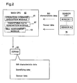
- FIG. 2 is an illustration depicting in detail the CPU 40, SDRAM 50, and sensor unit 70.
- the sensor unit 70 is equipped with a plurality of sensors 1 to n.
- the sensor unit 70 recognizes certain characteristics of a bill infed to the ATM 1000 by a user and transported along a transport path (not shown).
- the characteristics of a bill refer, for example, to the profile (outer shape), design, or thickness of the bill, or to a magnetic pattern.
- the sensor unit 70 outputs the recognized characteristics to the CPU 40, as bill characteristic data.
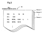
- FIG. 3 is an illustration depicting bill characteristic data Dt equivalent to a single bill.
- the bill characteristic data Dt represent bill characteristics recognized and output by the sensors 1 to n.
- Each item of bill characteristic data Dt0 -Dt3 recognized by the sensor 1 gives data values derived by recognizing a different characteristic.
- Each of the sensors 1 to n has multiple channels (e.g. the three channels R, G, B), and outputs the items of data over the multiple channels. In the case of the sensor 1 for example, since different numbers of channels for output of data are pre-selected for each item of bill characteristic data Dt0 -Dt3, the number of items of data differs among the bill characteristic data Dt0 -Dt3.
- the sensor unit 70 of FIG. 2 during times that no bill is being transported over the transport path, periodically executes scanning and outputs sensor data.
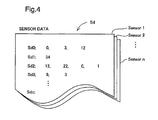
- This sensor data indicates a standard output representing the output of the sensor unit 70 in a prescribed standard state.
- FIG. 4 is an illustration depicting sensor data Sd equivalent to a single scan by the sensor unit 70.
- the configuration of this sensor data Sd is the same as the configuration of the bill characteristic data Dt.
- the sensor data Sd indicating the standard output of the sensor unit 70 may instead be data for a sample paper instrument recognized and output by the sensor unit 70.
- the CPU 40 of FIG. 2 functions as an operation command execution module 41, an identifying data generation module 42, and a bill assessment module 43.
- the operation command execution module 41 receives the operation command file 210 from the memory card controller 10, and then executes the operation command described in the operation command file 210. Operation commands will be described in detail later.
- the identifying data generation module 42 generates identifying data by means of performing computations of the bill characteristic data Dt with a prescribed plurality of computing equations.
- the identifying data is data for the purpose of identifying the type, authenticity, and possibility of recycling a bill.
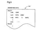
- FIG. 5 is an illustration depicting identifying data Jud.
- the identifying data Jud includes data Jud0 -Judn, and is generated for each individual bill.
- the bill assessment module 43 of FIG. 2 decides the type, authenticity, and possibility of recycling a bill, on the basis of the identifying data Jud.
- the CPU 40 saves the bill characteristic data Dt, the identifying data Jud, and the sensor data Sd in the SDRAM 50.
- the SDRAM 50 are saved bill characteristic data Dt, identifying data Jud, and sensor data Sd acquired since startup of the bill recognition unit 100.
- the data is not limited to this, and it would be acceptable for the SDRAM 50 to instead save bill characteristic data Dt and identifying data Jud relating to the most recent bill only; or to save bill characteristic data Dt and identifying data Jud equivalent to the most recent transaction. It is also acceptable for the SDRAM 50 to save sensor data Sd equivalent to only the most recent single scan by the sensor unit 70.
- the LED 80 of FIG. 1 indicates to the user whether the memory card 200 can be removed from the bill recognition unit 100.
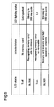
- FIG. 6 is an illustration depicting types of status of the LED 80.
- the status of the LED 80 will hereinafter be referred to simply as LED status.
- the LED status are Toff, BL500, Ton, and BL100. LED status changes depending on the detected state of the memory card 200 by the CPU 40.
- the detected states are "no memory card,” "recognizing memory card/safe to remove,” “recognizing memory card/not removable,” and “memory card memory area full/operation complete.”
- the CPU 40 In the "no memory card” detected state in which the memory card 200 is not connected to the memory card connector 60, the CPU 40 extinguishes the LED 80. This LED status is termed Toff. In the state of "recognizing memory card/safe to remove,” in which the memory card 200 is connected to the memory card connector 60, but the memory card 200 is not being accessed by the bill recognition unit 100 so that is it possible for the memory card 200 to be removed safely, the CPU causes the LED 80 to blink in a 500 ms cycle. This LED status is termed BL500.
- the CPU causes the LED 80 to light up.
- This LED status is termed Ton.
- the CPU causes the LED 80 to blink in a 100 ms cycle. This LED status is termed BL100.
- the memory card 200 stores the operation command file 210, the suffix code management file 220, and a change program 240; the data file memory section 230 is provided separately from these.
- the operation command file 210 stores operation commands.
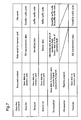
- FIG. 7 is an illustration depicting type and content of operation commands. These operation commands are: a bill characteristic data save command Save.dat; an identifying data save command Save.jud; a sensor data save command Monitor.sd; a command for execution in operating fault mode Survey.jud_sd; a command for execution in non-recyclable bill detected mode Trace.dat; and a change program execution command Change.prog.
- the CPU 40 acquires the bill characteristic data Dt currently saved in the SDRAM 50, and now saves this data, in the form of a data file 231, in the data file memory section 230 of the memory card 200.
- the file name under which the bill characteristic data Dt will be saved is specified by an argument of the bill characteristic data save command Save.dat.
- the file name of the data file be Datafile-xxx.
- "xxx" is a suffix code for the purpose of identifying the file.
- a data file is created for each set of bill characteristic data Dt equivalent to a single bill currently saved in the SDRAM 50, and suffix codes from 000 to 999 are assigned to these sequentially starting from 000.
- the data file initially saved to the data file memory section 230 after initiating execution of the bill characteristic data save command Save.dat will be assigned the file name Datafile-000.
- an argument of the bill characteristic data save command Save.dat can specify a file number of data files to be saved. For example, if the argument is 20, the CPU 40 will save 20 files. Also, if the argument is "all", the CPU 40 will take the bill characteristic data Dt equivalent to a single bill saved in the SDRAM 50 just prior to the memory card 200 being connected to the memory card connector 60, and all of the bill characteristic data Dt most recently placed in the SDRAM 50 during the time that the memory card 200 has been connected to the memory card connector 60, and save these data in data files in the data file memory section 230.
- the CPU 40 takes bill characteristic data Dt equivalent to a single bill saved in the SDRAM 50 just prior to the memory card 200 being connected to the memory card connector 60. and saves this data in a data file; however, it would be acceptable for all bill characteristic data Dt stored in the SDRAM 50 at the point in time that the memory card 200 was connected to be saved to data files.
- a data file is generated for each single bill, but is not limited thereto; data files may be generated on a per-transaction basis instead.
- the CPU 40 acquires the identifying data Jud currently saved in the SDRAM 50, and now saves it to a data file in the data file memory section 230 of the memory card 200.
- a file is created for each set of identifying data Jud equivalent to a single bill currently saved in the SDRAM 50.
- the file name during saving of identifying data Jud is Judfile-xxx.
- the manner of appending suffix codes to data files and the manner of establishing arguments of the identifying data save command Save.jud are the same as for the bill characteristic data save command Save.dat.
- the CPU 40 acquires the sensor data Sd currently saved in the SDRAM 50 and now saves it to a data file in the data file memory section 230 of the memory card 200.
- a file is created for each set of sensor data Sd equivalent to one scan by the sensor unit 70 currently saved in the SDRAM 50.
- the file name during saving of sensor data Sd is Sdfile-xxx.
- the manner of appending suffix codes xxx to data files and the manner of establishing arguments of the sensor data save command Monitor.sd are the same as for the bill characteristic data save command Save.dat.
- Sensor data Sd is generated at periodic intervals, and when sensor data Sd has been generated, the CPU 40 saves the data in a data file on the memory card 200.
- the CPU 40 acquires the identifying data Jud and the sensor data Sd that were saved in the SDRAM 50 at the time that the bill recognition unit 100 encountered the operating fault, and saves these data to the data file memory section 230 of the memory card 200 under the respective file names Suvjudfile-xxx and Suvsdfile.xxx. That is, the CPU 40, when triggered by the occurrence of an operating fault in the bill recognition unit 100, performs a save of the identifying data Jud and the sensor data Sd.
- An operating fault refers to an instance where, for example, in the course of a single transaction, a succession of bills are determined to be non-recyclable or counterfeit.
- the manner of appending suffix codes xxx to files is the same as for the bill characteristic data save command Save.dat. It is also acceptable for the decision as to whether or not an operating fault has occurred during a maintenance operation to be made by maintenance operators.
- the maintenance operator connects the memory card 200 to which the command for execution in operating fault mode Survey jud_sd has been saved to the memory card connector 60.
- the CPU 40 will execute the command for execution in operating fault mode Survey.jud_sd. That is, the identifying data Jud and sensor data will be saved to data files in the memory card 200. In some instances, at least some of the bill characteristic data Dt can be saved.
- the CPU 40 takes the bill characteristic data Dt relating to the bill determined to be non-recyclable that was saved to the SDRAM 50 when the bill assessment module 43 decided that the bill was non-recyclable, and saves this data to the data file memory section 230 of the memory card 200 under the file name Trcdatfile-xxx. That is, the CPU 40, when triggered by a decision by the bill assessment module 43 that a bill is non-recyclable, performs a save of the bill characteristic data Dt.
- the manner of appending suffix codes xxx to files is the same as for the bill characteristic data save command Save.dat.
- the CPU 40 executes the command for execution in non-recyclable bill detected mode Trace.dat when the bill assessment module 43 decides that a bill is non-recyclable, but the CPU 40 may also execute the command for execution in non-recyclable bill detected mode Trace.dat when the bill assessment module 43 decides that a bill is a counterfeit bill.
- the change program 240 is a program for varying the input/output characteristics (gain) of the sensor unit 70 by a rate of change specified by an argument. If no argument is specified, gain is varied by a prescribed value.
- the content of the change program execution command Change.prog is not limited to this; it would also be acceptable for the CPU 40, in the event that the operation command is the change program execution command Change.prog, to change the control program of the sensor unit 70 to the change program 240.
- a characteristic or program to be changed by the change program execution command Change.prog is specifiable by the argument of the change program execution command Change.prog.
- arguments that specify encoding of various kinds of data files can be appended to the arguments of operation commands.
- the CPU 40 will append a data file encoding request and output a data file, and the memory card controller 10 will perform encoding of the data file and save the encoded data file to the memory card 200.
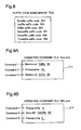
- FIG. 8 is an illustration depicting a suffix code management file 220.
- the suffix code management file 220 manages suffix codes appended to the various data files Datafile, Judfile, Sdfile, Suvjudfile, Suvsdfile, and Trcdatfile.
- the CPU 40 when creating a new file, appends to the file name a suffix code stored in the suffix code management file 220, and increments by 1 the suffix code in the suffix code management file 220.
- the suffix code management file 220 in the condition depicted in FIG. 8, in the event that a new Datafile is created, the file name Datafile-001 will be assigned, and the Datafile suffix code in the suffix code management file 220 will reset to 002.
- FIGs. 9A and 9B illustrate the content of the operation command file 210.
- FIG. 9A shows the operation command file Aaa.cmd 211 of FIG. 1;
- FIG. 9B shows the operation command file Bbb.cmd 212 of FIG. 1.
- the operation command file Aaa.cmd 211 includes three commands to be executed in sequence, which instruct that sensor data Sd be saved to the memory card 200 (Command 1); next that the gain of the sensor unit 70 be changed (Command 2); and then that sensor data Sd be saved to the memory card 200 (Command 3).
- the portions underlined with broken lines are arguments; in the sensor data save command Monitor.sd, the first argument specifies a file name for the data file, while the second specifies the number of data files to be created.
- the argument of the change program execution command Change.prog specifies a rate of change for gain.
- the symbol m in the drawing represents a positive integer.
- the sensor data Sd obtained as a result of execution of the operation command file Aaa.cmd 211 affords simulated realization, by means of the change program execution command Change.prog, of deterioration over time or environmental changes of the sensor unit 70; comparison of sensor data Sd obtained by execution of Command 1 with sensor data Sd obtained by execution of Command 3 affords data for the purpose of examining correction of the input/output characteristics of the sensor unit 70 during deterioration over time or environmental changes using bills in circulation in the service area.
- the change program execution command Change.prog changes the control program of the sensor unit 70 to the change program 240
- the sensor data Sd obtained by execution of Command 1 and Command 3 may serve as data for the purpose of examining change in control specifications.
- the operation command file Bbb.cmd 212 instructs that the gain of the sensor unit 70 be changed (Command 4); that bill characteristic data Dt be saved to the memory card (Command 5); and that the gain of the sensor unit 70 be changed again (Command 6).
- An argument of the change program execution command Change.prog specifies the rate of change of gain. Symbol k in the drawing is a positive constant.
- the first argument of the bill characteristic data save command Save.dat specifies a file name for the data files; the second argument specifies the number of data files to be created.
- the bill characteristic data Dt obtained as the result of execution of the operation command file Bbb.cmd 212 may serve as data for the purpose of examining the limits of bill detection capability due to degraded sensor output using bills in circulation in the service area, for example.
- FIG. 10 is an illustration depicting changes of gain of the sensor unit 70 when the CPU 40 executes the operation command files Aaa.cmd211 and Bbb.cmd212 in that order.
- the dotted line indicates gain under normal circumstances.
- the operation command files Aaa.cmd 211 and Bbb.cmd 212 instruct that the bill recognition unit 100 of the ATM 1000 be operated on a trial basis, and the data derived by execution of the operation command files Aaa.cmd 211 and Bbb.cmd 212 is utilized for maintenance of the bill recognition unit 100.
- the content of the operation command files 210 is not limited to that depicted in FIGs. 9A and 9B, and various settings are possible by means of combining the operation commands of FIG. 7. Also, the number of operation command files 210 is not limited to two, and may be set to any number equal to one or greater. It is also possible to encode the operation command files 210.
- FIG. 11 is a flowchart depicting a maintenance operation execution sequence.
- the LED status Prior to initiating the maintenance operation, the LED status is Toff.
- the maintenance operator brings the memory card 200 with the operation command files 210 established therein to the location of the ATM 1000, and inserts the memory card 200 into a slot (not shown) in the bill recognition unit 100. By so doing the memory card 200 is connected to the memory card connector 60.
- the CPU 40 sets the LED status to Ton, in order to indicate that preparation for memory access is in progress and the memory card 200 cannot be removed (Step S200).
- the CPU 40 carries out the operation command execution process (Step S300).
- FIG. 12 is a flowchart depicting the operation command execution process.
- the CPU 40 sets the LED status to BL100 (Step S302).
- the maintenance operator removes the memory card 200 from the bill recognition unit 100 (Step S303).
- the CPU 40 sets the LED status to Toff (Step S304).
- the process of Step S301 may be omitted.
- Step S301 In the event that there is a free area in the data file memory section 230 of the memory card 200 (Step S301: YES), the CPU 40 reads the operation command file Aaa.cmd 211 (Step S305) and sets the LED status to BL500 (Step S306). The CPU 40 then sets the LED status to Ton and executes the operation commands (Step S307).
- the CPU 40 may await a trigger in mid-process during execution of operation commands. During the time that the CPU 40 awaits a trigger it sets the LED status to BL500.
- the operation command is the command for execution in operating fault mode Survey .jud_sd or the command for execution in non-recyclable bill detected mode Trace.dat
- the operation command will be executed once an operating fault or non-recyclable bill has been detected as a trigger.
- the operation command is the bill characteristic data save command Save.dat
- it will wait until bill characteristic data Dt is recorded to the SDRAM 50, except in the case where bill characteristic data Dt has been previously saved to the SDRAM 50. That is, recording of bill characteristic data Dt to the SDRAM 50 is the trigger.
- the process for the identifying data save command Save.jud and the sensor data save command Monitor.sd is analogous to that for the bill characteristic data save command Save.dat.
- the maintenance operator In the case that the object of the maintenance is to acquire bill characteristic data Dt of a sample bill or reference bill, the maintenance operator, after connecting the memory card 200, performs a deposit transaction to the ATM 1000 by inserting the sample bill into the bill insertion opening of the ATM 1000 and making the sensor unit 70 scan the characteristics of the sample bill. By so doing, bill characteristic data Dt for the sample bill is saved to the SDRAM 50.
- the CPU 40 in accordance with the bill characteristic data save command Save.dat, takes the bill characteristic data Dt that was saved to the SDRAM 50 and saves it in a data file in the data file memory section 230.
- the CPU 40 may set the LED status to BL100 despite the fact that execution of the operation command is ongoing, and terminate the process.
- the CPU 40 executes saving of data files to the memory card 200 during times that the ATM 1000 is not performing transaction operations. However, in the event that the ATM 1000 attempts to initiate a transaction operation while a data file is being saved to the memory card 200, the start of the transaction operation will be suspended temporarily and wait until saving of the data file has been completed.
- Step S308 a check is made to determine if a next operation command file 210 exists (Step S400 of FIG. 11). In the event that a next operation command file (e.g. the operation command file Bbb.cmd 212) does exist, the operation command execution process is again carried out (Step S300). In the event that a next operation command file does not exist, the LED status is set to BL100 (Step S500). In this case, the maintenance operator removes the memory card 200 from the bill recognition unit 100 (Step S600). Once the memory card 200 is removed, the CPU 40 sets the LED status to Toff (Step S700).
- identifying data Jud and sensor data Sd (Suvjudfile and Suvsdfile) have been saved to the memory card 200 by means of the operation command execution process
- the maintenance operator can determine sensor status on the basis of the identifying data Jud and sensor data Sd, with the maintenance computer 300. Sensor status will be discussed in detail later.
- the maintenance computer 300 comprises a memory unit 310 and a sensor status assessment module 320.
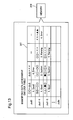
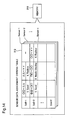
- the memory unit 310 stores the identifying data assessment criteria table 311 of FIG. 13 and the sensor data assessment criteria table 312 of FIG. 14.
- the sensor status assessment module 320 compares the identifying data Jud with the identifying data assessment criteria table 311, and compares the sensor data Sd with the sensor data assessment criteria table 312, to assess the sensor status.
- the sensor status assessment module 320 corresponds to the sensor status display module of the present invention.
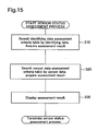
- FIG. 15 is a flowchart depicting the sensor status decision process of the sensor status assessment module 320.
- the sensor status assessment module 320 searches the identifying data assessment criteria table 311 with reference to the identifying data Jud, and acquires the assessment result (Step S10). Specifically, several items of data like those shown in FIG. 5 are present in the identifying data Jud.
- the sensor status assessment module 320 assesses sensor status for each individual item of data. For example, if the data value of Jud0 lies in a prescribed first range of OO ⁇ , an assessment of "1.
- the second item of data of Jud1 (denotes as Jud1-2 in the identifying data assessment criteria table 311) lies in a prescribed second range of OX ⁇ XX, an assessment of "3. warning” is made. Since n+1 pieces of data Jud0 -Judn exists for each bill, sensor status is assessed individually for these n+1 pieces of data Jud0 -Judn relating to all bills. From among the plurality of sensor status observations derived through assessment of sensor status for each of multiple data items, the sensor status assessment module 320 acquires as the assessment result the sensor status having the largest numerical value prefixed to the sensor status. That is, where the plurality of sensor status actually include "1. good,” "2. caution,” and "3. warning," "3.
- warning will be acquired as the assessment result. It is also acceptable to acquire all of the plurality of sensor status as assessment results. By making this kind of assessment, caution will be notified that the value of the identifying data for a genuine bill is approaching to a threshold value for assessing whether a bill is genuine or counterfeit, due to degraded sensor output. Using bills in circulation in the service area in the above procedure, those bills in circulation can be studied which generate the identifying data in approximation with the threshold value.
- the sensor status assessment module 320 searches the sensor data assessment criteria table 312 with reference to the sensor data Sd, and acquires the assessment result (Step S20).
- the specific assessment method is the same as in the case of identifying data Jud, and will not be described in detail.
- a sensor data assessment criteria table 312 is stored for each sensor 1 -n, and for the sensor data Sd0- Sdn relating to sensor 1, the sensor data assessment criteria table 312 relating to sensor 1 is used to assess the sensor status. Assessment results are acquired individually for sensors 1 -n.
- Step S30 The assessment results acquired in Steps S10 and S20 are displayed as sensor status on the monitor screen of the maintenance computer by the sensor status assessment module 320 (Step S30).
- the memory card 200 by attaching the memory card 200 to the bill recognition unit 100, a maintenance operator is able to easily acquire data of various kinds from the bill recognition unit 100 of the ATM 1000.
- the memory card 200 is easy to carry about. Operation content can be established in advance in an operation command file 210 so that the operation will proceed once the memory card 200 has been inserted into the slot of the bill recognition unit 100, so maintenance operations can be carried out without the need for any special technical skills on the part of the maintenance operator.
- the operation command files Aaa.cmd 211 and Bbb.cmd 212 the input/output characteristics of the sensor unit 70 can be changed, and data for maintenance purposes can be acquired consequently.
- sensor status is output by the maintenance computer 300, the user can ascertain the severity of impairment of a sensor. Since an LED 80 is provided and the LED status changes depending on the condition of access to the memory card 200, the user can ascertain whether it is possible for the memory card 200 to be removed from the bill recognition unit 100.
- operations to acquire bill characteristic data Dt, identifying data Jud, and sensor data Sd can be carried out with the memory card 200 only, without having to perform data acquisition operations remotely over a network or having to transmit data to the host computer 2000, and thus security can be maintained.
- Security can be enhanced further by means of encoding the data files 231, 232 and the operation command files 210.
- the encoded data files 231, 232 may be made decodable only by a designated administrator.
- the encoded operation command files 210 may be made decodable only by the memory card controller 10 or the creator of operation command files 210.
- data that cannot be stored in the ATM 1000 due to limited memory capacity can be saved to the memory card 200 as well.
- the memory card 200 of the embodiment can also be used in instances where there are limitations of communication time and so on, so that bill characteristic data Dt cannot be transmitted to the ATM 1000 which is the parent device of the bill recognition unit 100.
- LED status at completion of an operation is the same as that when the memory area of the memory card 200 is full; however, distinct status could be use instead.
- the LED status at completion of an operation could be indicated by making the LED blink at 200 ms intervals.
- the sensor status assessment module 320 assesses sensor status on the basis of identifying data Jud and sensor data Sd, but an operation command to acquire bill characteristic data Dt may be provided as well, and sensor status may be output on the basis of the bill characteristic data Dt.
- the preceding embodiment describes the sensor unit 70 as periodically outputting sensor data Sd, this arrangement is not limiting, it being possible instead for the CPU 40 to instruct the sensor unit 70 to output sensor data Sd in the event that a sensor data save command Monitor.sd has been issued, and for the sensor unit 70 to output sensor data Sd in response.
- the interval for outputting the sensor data Sd is specifiable by an argument of the sensor data save command Monitor.sd.
- the CPU 40 issues to the sensor unit 70 an instruction to halt output of sensor data Sd.
- the preceding embodiment describes the input/output characteristics (gain) of the sensor unit 70, i.e. the sensor characteristics, being changed in the event that an operation command is the change program execution command Change.prog, the changed parameter is not limited to sensor characteristics, it being possible to change some other operating characteristic of the ATM 1000 or the bill recognition unit 100.
- the assessment may instead be carried out by the ATM 1000 or the bill recognition unit 100.
- the bill recognition unit 100 in the event that identifying data is close to the threshold value, i.e. "caution” or "warning," the bill characteristic data Dt for the bill can be acquired to the memory card 200. It is also possible to raise an alarm with the parent controller 110 or the ATM 1000 before sensor deterioration results in failure mode.
- the paper handling apparatus is not limited thereto, and could instead be a vending machine, cash dispenser, or ticket machine.
- the portable memory medium is not limited to a memory card 200.
- the portable memory medium may employ some other memory medium such as a hard disk or DVD-RAM.
Landscapes
- Physics & Mathematics (AREA)
- General Physics & Mathematics (AREA)
- Business, Economics & Management (AREA)
- Accounting & Taxation (AREA)
- Finance (AREA)
- Engineering & Computer Science (AREA)
- Marketing (AREA)
- Economics (AREA)
- Development Economics (AREA)
- Strategic Management (AREA)
- Technology Law (AREA)
- General Business, Economics & Management (AREA)
- Theoretical Computer Science (AREA)
- Inspection Of Paper Currency And Valuable Securities (AREA)
- Financial Or Insurance-Related Operations Such As Payment And Settlement (AREA)
- Accessory Devices And Overall Control Thereof (AREA)
Applications Claiming Priority (1)
| Application Number | Priority Date | Filing Date | Title |
|---|---|---|---|
| JP2005294378A JP4804864B2 (ja) | 2005-10-07 | 2005-10-07 | 紙幣取扱システム |
Publications (2)
| Publication Number | Publication Date |
|---|---|
| EP1783698A2 true EP1783698A2 (de) | 2007-05-09 |
| EP1783698A3 EP1783698A3 (de) | 2008-07-23 |
Family
ID=37602992
Family Applications (1)
| Application Number | Title | Priority Date | Filing Date |
|---|---|---|---|
| EP06020568A Withdrawn EP1783698A3 (de) | 2005-10-07 | 2006-09-29 | System und Verfahren zur Verarbeitung von Blättern |
Country Status (4)
| Country | Link |
|---|---|
| EP (1) | EP1783698A3 (de) |
| JP (1) | JP4804864B2 (de) |
| KR (1) | KR100856529B1 (de) |
| CN (1) | CN100587733C (de) |
Cited By (2)
| Publication number | Priority date | Publication date | Assignee | Title |
|---|---|---|---|---|
| WO2012175542A1 (de) * | 2011-06-21 | 2012-12-27 | Bundesdruckerei Gmbh | Verfahren und vorrichtung zum erstellen eines dokumentenreferenzdatensatzes anhand eines dokumentes |
| EP2431950A4 (de) * | 2009-04-27 | 2013-03-06 | Toshiba Kk | System zur papierblattverarbeitung |
Families Citing this family (8)
| Publication number | Priority date | Publication date | Assignee | Title |
|---|---|---|---|---|
| JP2009253832A (ja) * | 2008-04-09 | 2009-10-29 | Mitsubishi Electric Building Techno Service Co Ltd | 監視映像録画複写システム |
| JP5238360B2 (ja) * | 2008-05-30 | 2013-07-17 | 富士通フロンテック株式会社 | 自動取引装置および係員操作処理の自動化方法 |
| JP2011076244A (ja) * | 2009-09-29 | 2011-04-14 | Fujitsu Frontech Ltd | 紙葉類鑑別システム、紙葉類鑑別方法及び紙葉類処理装置 |
| ES2562264T5 (es) | 2010-05-25 | 2019-06-24 | Arc Medical Design Ltd | Cubierta para dispositivo médico de exploración |
| DE102010046024A1 (de) * | 2010-09-20 | 2012-03-22 | Giesecke & Devrient Gmbh | Sensor zur Prüfung von Wertdokumenten |
| CN105374114B (zh) * | 2014-08-27 | 2017-12-12 | 日立金融设备系统(深圳)有限公司 | 货币处理装置及其管理方法、以及货币处理系统 |
| CN105869309A (zh) * | 2016-03-24 | 2016-08-17 | 广州广电运通信息科技有限公司 | 驱动模块内存数据监测方法及装置 |
| KR102247213B1 (ko) | 2019-11-27 | 2021-05-04 | 한국생산기술연구원 | 이산화탄소 용매를 이용한 디메티콘의 제조방법 |
Citations (1)
| Publication number | Priority date | Publication date | Assignee | Title |
|---|---|---|---|---|
| EP1256102B1 (de) * | 2000-02-14 | 2003-07-23 | Cashcode Company Inc. | Prufer mit auswechselbarem flashspeicher |
Family Cites Families (13)
| Publication number | Priority date | Publication date | Assignee | Title |
|---|---|---|---|---|
| DE3639755A1 (de) * | 1985-11-22 | 1987-05-27 | Oki Electric Ind Co Ltd | Selbstdiagnoseverfahren fuer ein geraet |
| JPH0416238Y2 (de) * | 1986-07-23 | 1992-04-10 | ||
| JPS63231695A (ja) * | 1987-03-20 | 1988-09-27 | 富士通株式会社 | 自動取引装置のテスト制御方式 |
| JPH01251165A (ja) * | 1988-03-31 | 1989-10-06 | Oki Electric Ind Co Ltd | 現金自動取引装置の保守情報収集方式 |
| JP2726551B2 (ja) * | 1990-05-31 | 1998-03-11 | 株式会社東芝 | 現金処理システム |
| JPH06150114A (ja) * | 1992-11-16 | 1994-05-31 | Hitachi Ltd | 紙幣入出金装置 |
| GB9626834D0 (en) * | 1996-12-24 | 1997-02-12 | Ncr Int Inc | Improved self service terminal |
| US6109522A (en) * | 1997-11-28 | 2000-08-29 | Diebold, Incorporated | Automated banking machine with self auditing capabilities and system |
| GB9816504D0 (en) * | 1998-07-30 | 1998-09-23 | Ncr Int Inc | Data processing and method |
| JP2002024912A (ja) * | 2000-07-12 | 2002-01-25 | Oki Electric Ind Co Ltd | 自動取引装置におけるスクリプト実行方法 |
| JP2003006715A (ja) * | 2001-06-20 | 2003-01-10 | Hitachi Ltd | 現金自動取引装置 |
| JP2004094624A (ja) * | 2002-08-30 | 2004-03-25 | Toshiba Corp | 紙葉類処理装置、および紙葉類処理方法 |
| KR20060001703A (ko) * | 2004-06-30 | 2006-01-06 | 노틸러스효성 주식회사 | 단일 제어부를 이용한 복수 금융자동화기기 제어장치 |
-
2005
- 2005-10-07 JP JP2005294378A patent/JP4804864B2/ja not_active Expired - Fee Related
-
2006
- 2006-09-29 EP EP06020568A patent/EP1783698A3/de not_active Withdrawn
- 2006-10-02 KR KR1020060096874A patent/KR100856529B1/ko not_active Expired - Fee Related
- 2006-10-08 CN CN200610142132A patent/CN100587733C/zh not_active Expired - Fee Related
Patent Citations (1)
| Publication number | Priority date | Publication date | Assignee | Title |
|---|---|---|---|---|
| EP1256102B1 (de) * | 2000-02-14 | 2003-07-23 | Cashcode Company Inc. | Prufer mit auswechselbarem flashspeicher |
Cited By (3)
| Publication number | Priority date | Publication date | Assignee | Title |
|---|---|---|---|---|
| EP2431950A4 (de) * | 2009-04-27 | 2013-03-06 | Toshiba Kk | System zur papierblattverarbeitung |
| US8408398B2 (en) | 2009-04-27 | 2013-04-02 | Kabushiki Kaisha Toshiba | Sheet handling system |
| WO2012175542A1 (de) * | 2011-06-21 | 2012-12-27 | Bundesdruckerei Gmbh | Verfahren und vorrichtung zum erstellen eines dokumentenreferenzdatensatzes anhand eines dokumentes |
Also Published As
| Publication number | Publication date |
|---|---|
| EP1783698A3 (de) | 2008-07-23 |
| KR100856529B1 (ko) | 2008-09-04 |
| KR20070039402A (ko) | 2007-04-11 |
| CN100587733C (zh) | 2010-02-03 |
| JP2007102659A (ja) | 2007-04-19 |
| JP4804864B2 (ja) | 2011-11-02 |
| CN1945638A (zh) | 2007-04-11 |
Similar Documents
| Publication | Publication Date | Title |
|---|---|---|
| AU2004250589B2 (en) | System and method for monitoring and diagnosis of point of sale devices having intelligent hardware | |
| JP6291908B2 (ja) | 金銭処理装置用の操作ガイダンス表示システム、プログラムおよび記録媒体 | |
| EP1783698A2 (de) | System und Verfahren zur Verarbeitung von Blättern | |
| CN104821042A (zh) | 自助服务终端的带外监控和管理 | |
| WO2011119261A1 (en) | Self-service device inventory information control | |
| US7788633B2 (en) | Bank note processing machine and method for operating bank note processing machine | |
| JP7362372B2 (ja) | 紙幣処理システムの遠隔保守システム、および遠隔保守方法 | |
| CN113470245A (zh) | 基于大数据管理的信号匹配系统 | |
| JP4571521B2 (ja) | 作業指示リスト印刷方法、および、印刷プログラム | |
| KR20140055160A (ko) | 금융기기의 장애관리장치 및 방법, 그리고 장애관리시스템 | |
| CN116739769A (zh) | 一种数据检测的方法、装置、电子设备及存储介质 | |
| JP4634966B2 (ja) | 設備データ解析処理システムとその方法 | |
| JP2003006001A (ja) | 業務処理ソフトウエアのテスト装置 | |
| CN112288961A (zh) | 一种自动柜员机巡查装置、巡查系统以及巡查方法 | |
| CN206451300U (zh) | 一种金融交易设备 | |
| CN110533400A (zh) | 一种支票存款的方法、装置、设备及存储介质 | |
| AU2008202290B2 (en) | Method And System for Linking Electronic Artefacts | |
| CN201166876Y (zh) | 银行身份识别系统 | |
| KR20140116663A (ko) | 금융기기 모듈 동작 프로그램의 상태를 나타내는 장치 및 방법 | |
| CN111142411A (zh) | 设备点检装置及设备点检系统 | |
| CN117973354A (zh) | 二次措施单的处理方法、装置、存储介质和处理器 | |
| JP2021089600A (ja) | 紙葉類処理装置、紙葉類処理システム及び紙葉類識別方法 | |
| CN121092695A (zh) | 敏感词检测方法、装置、电子设备及介质 | |
| JP4901403B2 (ja) | ソフトウェア部品管理システム | |
| CN121542151A (zh) | 灰度流量状态的确定方法、装置、存储介质及电子设备 |
Legal Events
| Date | Code | Title | Description |
|---|---|---|---|
| PUAI | Public reference made under article 153(3) epc to a published international application that has entered the european phase |
Free format text: ORIGINAL CODE: 0009012 |
|
| AK | Designated contracting states |
Kind code of ref document: A2 Designated state(s): AT BE BG CH CY CZ DE DK EE ES FI FR GB GR HU IE IS IT LI LT LU LV MC NL PL PT RO SE SI SK TR |
|
| AX | Request for extension of the european patent |
Extension state: AL BA HR MK YU |
|
| 17P | Request for examination filed |
Effective date: 20080331 |
|
| PUAL | Search report despatched |
Free format text: ORIGINAL CODE: 0009013 |
|
| AK | Designated contracting states |
Kind code of ref document: A3 Designated state(s): AT BE BG CH CY CZ DE DK EE ES FI FR GB GR HU IE IS IT LI LT LU LV MC NL PL PT RO SE SI SK TR |
|
| AX | Request for extension of the european patent |
Extension state: AL BA HR MK RS |
|
| AKX | Designation fees paid |
Designated state(s): DE FR GB |
|
| 17Q | First examination report despatched |
Effective date: 20090309 |
|
| STAA | Information on the status of an ep patent application or granted ep patent |
Free format text: STATUS: THE APPLICATION IS DEEMED TO BE WITHDRAWN |
|
| 18D | Application deemed to be withdrawn |
Effective date: 20160727 |