EP1783786A2 - Kabelsystem mit magnetischer Schirmungshülle - Google Patents
Kabelsystem mit magnetischer Schirmungshülle Download PDFInfo
- Publication number
- EP1783786A2 EP1783786A2 EP06022902A EP06022902A EP1783786A2 EP 1783786 A2 EP1783786 A2 EP 1783786A2 EP 06022902 A EP06022902 A EP 06022902A EP 06022902 A EP06022902 A EP 06022902A EP 1783786 A2 EP1783786 A2 EP 1783786A2
- Authority
- EP
- European Patent Office
- Prior art keywords
- voltage cable
- cable according
- shielding
- tube
- cores
- Prior art date
- Legal status (The legal status is an assumption and is not a legal conclusion. Google has not performed a legal analysis and makes no representation as to the accuracy of the status listed.)
- Granted
Links
Images


Classifications
-
- H—ELECTRICITY
- H01—ELECTRIC ELEMENTS
- H01B—CABLES; CONDUCTORS; INSULATORS; SELECTION OF MATERIALS FOR THEIR CONDUCTIVE, INSULATING OR DIELECTRIC PROPERTIES
- H01B9/00—Power cables
- H01B9/02—Power cables with screens or conductive layers, e.g. for avoiding large potential gradients
- H01B9/023—Power cables with screens or conductive layers, e.g. for avoiding large potential gradients composed of helicoidally wound tape-conductors
Definitions
- the invention relates to a cable system, in particular for three-phase current with magnetic shielding shell.
- High-voltage cables are advantageous over overhead lines because they do not generate an electric field in their environment.
- the low frequency external magnetic field generated by the cable currents is present.
- a well-known shielding measure is the insertion of the cables in a steel tube with three stranded and steel wire-reinforced 110 kV cable wires: Brochure (1999), No. E21.2d 1.0; "City cable” of the company nkt cables GmbH, Cologne.
- the steel tube has a magnetic shielding, but this construction is expensive and has other disadvantages, such as the need to weld together short, rigid steel pipe sections and protect the steel pipes against corrosion.
- the particles are placed in a braided screen, either introducing the particles into the mesh or gaps of the screen, or adhering the particles to the mesh. Both are very complex and therefore disadvantageous process steps.
- the essence of the invention consists in that at least one layer comprising the cable cores, hereinafter referred to as a sheath shell, is applied as a winding of at least one band of magnetically highly permeable material.
- a cable construction according to the invention can be provided in which three stranded and steel wire-reinforced cable cores are drawn into an outer tube.
- the structure is such that below one steel wire reinforcement one or more layers of so-called electrical tapes are applied, optionally in combination with compensation conductors or conductive layers.
- Such electrical bands consist of low silicon silicon steel strip ( ⁇ 2.5%) and are made in a thickness of 0.02 to 0.04 mm. They are cold-rolled, grain-oriented or non-grain-oriented and have excellent magnetic properties such as high permeability and low core loss.
- the electrical tapes to be used have good mechanical resistance and a favorable price. They already have a very thin (micrometer-range) insulating layer from the manufacturing process, but can also be surface-coated by additional processes, for example galvanized.
- the effect of the magnetic shield is optimal if the cable system does not carry zero current. This should be the case for an "ideal" three-phase system.
- Important in the case of the magnetic shielding of a three-phase cable is that all three cable cores are jointly covered by the high-permeability shielding sheath. Therefore, the shielding tapes are wound over the three stranded cable cores.
- Occurring zero currents in a three-phase system can only be shielded by inducing countercurrents in highly conductive electrical conductors in their environment which compensate the magnetic field by means of an opposing field. This also applies to other than three-wire cable construction, where there is no symmetry of the magnetic fields emanating from the cable cores.
- a small lay length in grain-oriented tapes is critical to guiding the circular magnetic field in the preferred magnetic direction (this is the longitudinal direction) of the tapes. Even with non-grain oriented tapes, the magnetic resistance of the layer is minimized by a short lay length.
- the advantage of a short lay length is also that the bands can move against each other when bending the cable.
- the straps of the magnetic shielding sheath are to be applied with a short lay length, they can not take over the function of a reinforcement to absorb and retain tensile forces from the cable ends when pulling in the cables, therefore, the reinforcement is added to the cable structure.
- the magnetic shielding measures described above can also be carried out for two cable cores adjacent to one another in a single-conductor or two-core cable construction, one of which carries the current in one direction and the other returns the current, as in the case of a single-phase AC system or a bipolar DC system is the case.
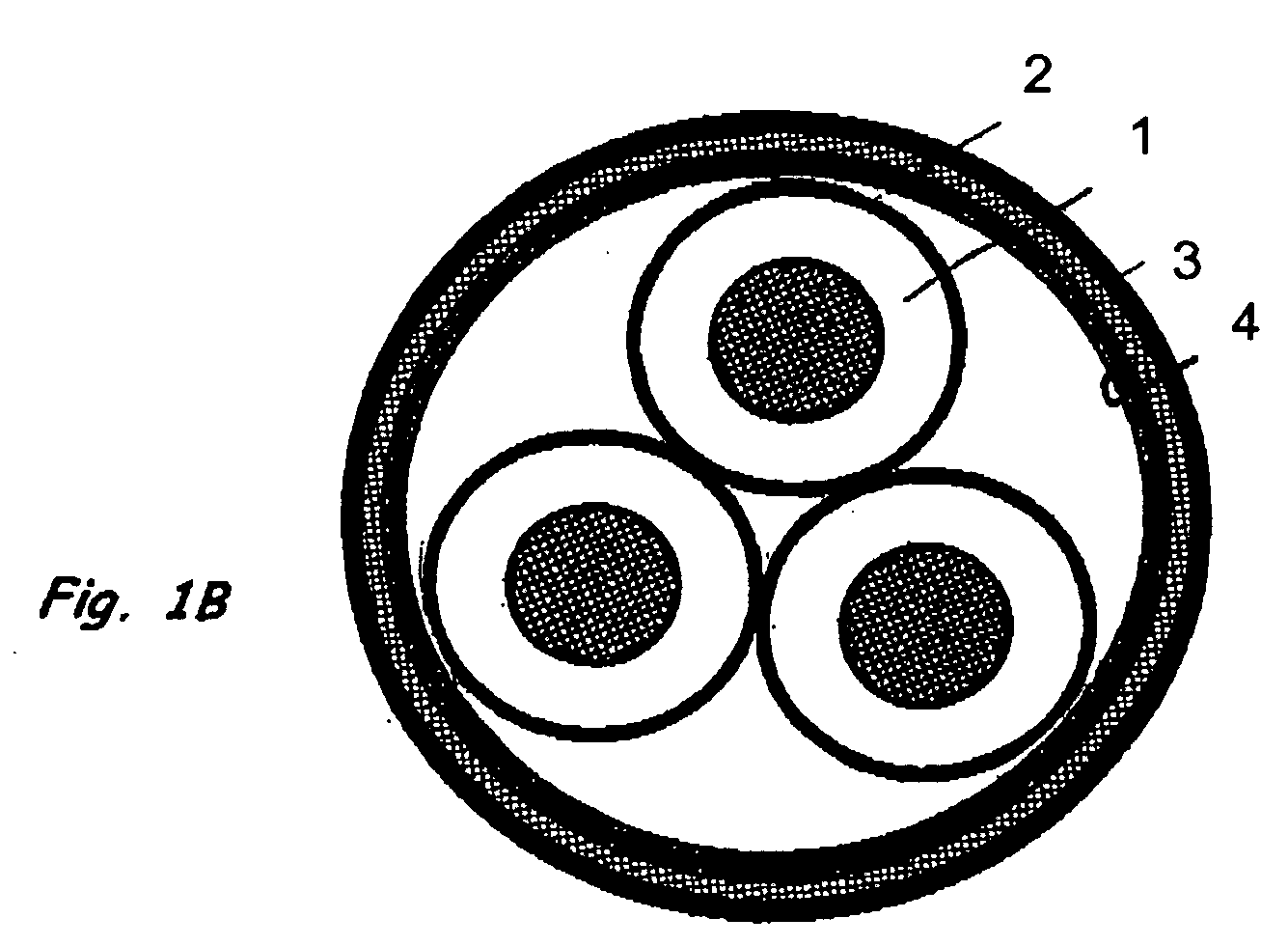
- Fig. 1 shows a high voltage cable for three-phase current with three stranded wires 1, a magnetically shielding layer 2 (Schirmungshülle) and a reinforcement 3, wherein the reinforcement has to take over the task of Jardinyakierin where the cable in cable trenches, in pipes or culverts is retractable.
- the conductors of the wires are insulated as usual and the insulation provided with inner and outer conductive layer.
- a magnetically shielded, armored three-conductor cable is shown in the partial figure 1A.
- Sub-figure 1 B corresponds to 1A, but in addition with a highly conductive layer 4 below the belt layer.
- the subfigure 1C differs from subfigure 1A by an additional compensation conductor 5 within the band layer.
- Fig. 2 shows a magnetically shielded arrangement in the socket area.
- An outer shielding tube 6 for the sleeve shield and sleeves 7 are shown.
- FIG. 1A shows a first variant of the solution with reinforcement located above the shielding shell.
- This reinforcement can consist of strips or wires, for example made of steel or bronze, preferably also formed as a flat wire.
- reinforcement and shielding shell complement each other both electromagnetically and mechanically.
- the magnetic shield In the socket areas, the magnetic shield must be interrupted by settling the reinforcement and the shielding shell, so that additional measures must be taken here.
- An effective shielding within this range can be achieved as shown in Fig. 2: over the entire sleeve assembly, a magnetically effective tube 6 is pushed.
- This pipe can be a steel pipe with the required wall thickness. But it can also be configured as a plastic composite pipe by a plastic pipe is wrapped with one or more layers of electrical tapes, similar to the stranded cable wires 1 in the other areas.
- the outer shielding tube 6 is magnetically tightly connected at its ends with the Schirmungshülle 2 of the cable cores. From the point of view of magnetic shielding, it is sufficient if the outer shielding tube 6 overlaps the offset ends of the shielding sheath of the cable cores by a length corresponding to its diameter. Under grounding considerations, it will be useful to electrically connect the outer shielding tube to the shielding sheath of the cable cores.
Landscapes
- Communication Cables (AREA)
- Insulated Conductors (AREA)
Abstract

Description
- Die Erfindung betrifft ein Kabelsystem, insbesondere für Drehstrom mit magnetischer Schirmungshülle.
- In zunehmendem Maße wird bei der Installation von Hochspannungskabeln und Freileitungen die Forderung erhoben, elektromagnetische Felder abzuschirmen.
- Hierbei sind Hochspannungskabel gegenüber Freileitungen von Vorteil, weil sie in ihrer Umgebung kein elektrisches Feld erzeugen. Allerdings ist bei gängigen Kabelkonstruktionen das durch die Kabelströme erzeugte niederfrequente äußere Magnetfeld vorhanden.
- Eine bereits bekannte Abschirmmaßnahme ist das Einziehen der Kabel in ein Stahlrohr mit drei verseilten und stahldrahtbewehrten 110-kV-Kabeladern: Broschüre (1999), Nr. E21.2d 1.0; "Stadtkabel" der Firma nkt cables GmbH, Köln. Das Stahlrohr weist zwar eine magnetische Abschirmwirkung auf, doch ist diese Konstruktion kostenaufwendig und weist weitere Nachteile auf, beispielsweise die Erfordernisse, kurze, starre Stahlrohrabschnitte aneinanderzuschweißen und die Stahlrohre gegen Korrosion schützen zu müssen.
- Das Abschirmen von Hoch- oder Miftelspannungskabeln mit weichmagnetischem (hochpermeablem) Material ist bekannt. Geeignete Materialien lassen sich jedoch nicht in großflächiger Form einsetzen, da die Materialien mechanisch relativ spröde Eigenschaften haben, die zur Einschränkung der Biegbarkeit der Kabel führt. Kabel sollte jedoch eine gewisse Biegbarkeit aufweisen, weil dies im Herstellprozess und während des Verlegens von Vorteil ist. Um die geforderte Biegbarkeit und Flexibilität nicht einzuschränken, wurde schon vorgeschlagen, hochpermeable Materialien in Form von Teilchen (
DE 19807527 A1 ) oder in Bandform (DE 3123040 A1 ) zu verwenden. - In der
DE 19807527 A1 werden die Teilchen in einem als Geflecht aufgebauten Schirm eingebracht, wobei entweder das Einbringen der Teilchen in die Maschen oder Lücken des Schirms vorgeschlagen wird oder die Teilchen auf das Geflecht aufgeklebt werden. Beides sind sehr aufwendige und daher nachteilige Verfahrensschritte. - In der
DE 3123040 A1 wird die Herstellung einer magnetischen Schirmungshülle durch Verwendung zweier Bänder dargestellt. Die Bebänderung erfolgt mit Abstand der Wicklungen, so dass Luftspalte entstehen, die die Biegbarkeit und Flexibilität des Kabels erhalten, jedoch eine doppelte Bebänderung erfordern. Damit werden die Luftspalte der unteren Bandlage durch die (in Gegenschlag) aufgebrachte obere Bandlage abgedeckt. - Es ist die Aufgabe der Erfindung, ein Kabelsystem mit nicht notwendig hoher Biegbarkeit des Kabels anzugeben, bei dem das durch die Kabelströme erzeugte niederfrequente äußere Magnetfeld weitestgehend unterdrückt wird.
- Die Lösung der Aufgabe findet sich im Hauptanspruch. Weiterführende Ausführungsformen werden in den Unteransprüchen formuliert.
- Der Kern der Erfindung besteht darin, dass mindestens eine die Kabeladern umfassende, im folgenden als Schirmungshülle bezeichnete Schicht als Wicklung mindestens eines Bandes aus magnetisch hochpermeablem Material aufgebracht ist.
- Für ein Drehstromsystem kann eine erfindungsgemäße Kabelkonstruktion vorgesehen sein, bei der drei verseilte und stahldrahtbewehrte Kabeladern in ein äußeres Rohr eingezogen werden. Der Aufbau ist so, dass unterhalb einer Stahldrahtarmierung eine oder mehrere Schichten aus sogenannten Elektrobändern aufgebracht werden, gegebenenfalls in Kombination mit Kompensationsleitern oder -leitschichten.
- Solche Elektrobänder, wie sie im Transformatoren- und Elektromaschinenbau verwendet werden, bestehen aus Silicium-Stahlblechbändern mit geringem Siliciumanteil (< 2,5 %) und werden in einer Dicke von 0,02 bis 0,04 mm hergestellt. Sie sind kaltgewalzt, kornorientiert oder nicht-kornorientiert, und sie weisen hervorragende magnetische Eigenschaften wie hohe Permeabilität und geringe Ummagnetisierungsverluste auf.
- Ebenfalls sehr gute magnetische Eigenschaften, wie sie hier vorausgesetzt oder gefordert werden, haben die sogenannten metallischen Gläser. Im Handel werden diese unter der Bezeichnung Mumetall oder Vitrovac von der Firma Vacuumschmelze angeboten. Solche speziellen, nichtkristallinen Nickel-Eisenlegierungen werden schon für ortsfeste bzw. starre Abschirmanordnungen eingesetzt. Sie werden in einem aufwendigen Verfahren hergestellt, und haben allerdings den Nachteil der immens hohen Kosten einerseits und der schlechten Verarbeitbarkeit andererseits. Kritisch wäre auch die Biegebeanspruchung, die bei der Kabelherstellung und später bei der Installation auftritt.
- Die einzusetzenden Elektrobänder haben demgegenüber eine gute mechanische Beanspruchbarkeit und einen günstigen Preis. Sie weisen schon vom Herstellungsprozess her eine sehr dünne (Mikrometerbereich) Isolierschicht auf, können aber auch durch zusätzliche Prozesse oberflächenbeschichtet, beispielsweise verzinkt werden.
- Die Wirkung der magnetischen Abschirmung ist dann optimal, wenn das Kabelsystem keinen Nullstrom führt. Dies dürfte für bei einem "idealen" Drehstromsystem der Fall sein. Wichtig bei der magnetischen Schirmung eines Drehstromkabels ist, dass alle drei Kabeladern gemeinsam von der hochpermeablen Schirmungshülle umfasst werden. Daher werden die Abschirmbänder über die drei verseilten Kabeladern gewickelt. Um hohe magnetische Leitwerte der Schirmungshülle zu erhalten und um das die Kabeladern etwa zirkular umgebende Magnetfeld optimal zu führen, ist es wichtig, die Abschirmbänder mit kleiner Schlaglänge um die Kabeladern zu wickeln. Hierdurch liegt die Wicklung der Abschirmbänder fast rechtwinklig zur Längsrichtung der Kabeladern.
- Auftretende Nullströme in einem Drehstromsystem können nur dadurch abgeschirmt werden, dass sie in hochleitfähigen elektrischen Leitern in ihrer Umgebung Gegenströme induzieren, die durch ein Gegenfeld das Magnetfeld kompensieren. Dies gilt auch bei einem anderen als dreiadrigem Kabelaufbau, wo keine Symmetrie der von den Kabeladern ausgehenden Magnetfeldern vorliegt.
- Deshalb wird als weitere Ausführungsform vorgeschlagen, in Kombination mit den magnetischen Abschirmbändern zusätzliche hochleitfähige Schichten oder Einzelleiter in den Kabelaufbau zu integrieren. Abhängig von der geforderten Minderung des magnetischen Streufeldes kann schon eine Lage von Abschirmbändern ausreichen. In den meisten Fällen sollte eine zweilagige Schirmungshülle den gewünschten Zweck erfüllen.
- Beim Aufbringen der Bänder ist eine kleine Schlaglänge bei kornorientierten Bändern entscheidend, um das zirkulare Magnetfeld in der magnetischen Vorzugsrichtung (dies ist die Längsrichtung) der Bänder zu führen. Auch bei nicht-kornorientierten Bändern wird durch eine kleine Schlaglänge der magnetische Widerstand der Schicht minimiert. Der Vorteil einer kurzen Schlaglänge ist auch, dass sich die Bänder beim Biegen des Kabels gegeneinander verschieben können.
- Da die Bänder der magnetischen Schirmungshülle mit kleiner Schlaglänge aufgebracht werden sollen, können sie nicht die Funktion einer Armierung übernehmen, um Zugkräfte von den Kabelenden beim Einziehen der Kabel aufzunehmen und zu halten, daher kommt zum Kabelaufbau die Armierung hinzu.
- Die zuvor beschriebenen Maßnahmen zur magnetischen Schirmung lassen sich auch ausführen für zwei in einer Einleiterkabel- oder in einer Zweileiterkabelkonstruktion nebeneinander liegende Kabeladern, von denen die eine den Strom in die eine Richtung führt und die andere den Strom zurückführt, wie dies beispielsweise bei einem einphasigen Wechselspannungssystem oder einem bipolaren Gleichspannungssystem der Fall ist.
- Mehrere Ausgestaltungen der Erfindung werden in den Figuren dargestellt, welche im Einzelnen zeigen:
- Fig. 1 drei Konstruktionen eines magnetisch geschirmten, armierten Dreileiterkabels und
- Fig. 2 eine magnetisch geschirmte Anordnung im Muffenbereich.
- Die Fig. 1 zeigt ein Hochspannungskabel für Drehstrom mit drei verseilten Adern 1, einer magnetisch schirmenden Schicht 2 (Schirmungshülle) und einer Armierung 3, wobei die Armierung die Aufgabe von Kabelzugelementen zu übernehmen hat, an denen das Kabel in Kabelgräben, in Rohre oder Düker einziehbar ist. Die Leiter der Adern sind wie üblich isoliert und die Isolierung mit innerer und äußerer Leitschicht versehen. In der Teilfigur 1A ist ein magnetisch geschirmtes, armiertes Dreileiterkabel dargestellt. Teilfigur 1 B entspricht 1A, aber zusätzlich mit einer hochleitfähigen Schicht 4 unterhalb der Bandschicht. Die Teilfigur 1C unterscheidet sich von Teilfigur 1A durch einen zusätzlichen Kompensationsleiter 5 innerhalb der Bandschicht.
- Die Fig. 2 zeigt eine magnetisch geschirmte Anordnung im Muffenbereich. Wobei ein äußeres Schirmungsrohr 6 für die Muffenschirmung und Muffen 7 dargestellt sind.
- Die Fig. 1A zeigt eine erste Lösungsvariante mit über der Schirmungshülle liegende Armierung. Diese Armierung kann aus Bändern oder -drähten, beispielsweise aus Stahl oder Bronze, vorzugsweise auch als Flachdraht ausgebildet, bestehen. Bei geeigneter Auslegung ergänzen sich Armierung und Schirmungshülle sowohl elektromagnetisch wie auch mechanisch.
- Wie schon angesprochen, funktioniert die beschriebene Art der magnetischen Abschirmung dann optimal, wenn ein Drehstromsystem keinen Nullstrom führt. (Erklärung: Ohne Nullstrom ergänzen sich die drei Ströme eines Drehstromsystems in jedem Augenblick zu Null).
- Es wird daher für Drehstromsysteme oder für andere als dreiadrige Kabelkonstruktionen vorgeschlagen, die Abschirmung dadurch zu unterstützen, dass in Kombination mit den magnetischen Abschirmbändern zusätzliche hochleitfähige Schichten 4 oder Einzelleiter 5 in den Kabelaufbau eingebracht werden. Nullströme oder Unsymmetrieströme induzieren in den hochleitfähigen elektrischen Leitern in ihrer Umgebung Gegenströme, die durch ein Gegenfeld das Magnetfeld kompensieren. Dabei wird die beste Abschirmwirkung erreicht, wenn diese sich innerhalb der magnetischen Bandschicht befinden. Zwei Lösungsvarianten sind in den Teilabbildungen Fig. 1 B und 1C dargestellt, wo die Kompensationsleiter als eingezogene Einzelleiter 5 oder als leitfähige Schicht 4 unter der Schirmungshülle dargestellt sind. Eine weitere, nicht dargestellte Möglichkeit besteht in der Anordnung einer koaxialen hochleitfähigen Hülle um jede Kabelader; somit auch hier unterhalb der Schirmungshülle.
- In den Muffenbereichen muss die magnetische Schirmung durch Absetzen der Armierung und der Schirmungshülle unterbrochen werden, so dass hier zusätzliche Maßnahmen ergriffen werden müssen. Eine wirksame Schirmung innerhalb dieses Bereiches kann so erreicht werden, wie dies in der Fig. 2 dargestellt ist: über die gesamte Muffenanordnung wird ein magnetisch wirksames Rohr 6 geschoben. Dieses Rohr kann ein Stahlrohr mit der erforderlichen Wanddicke sein. Es kann aber auch als Kunststoff-Verbundrohr ausgestaltet sein, indem ein Kunststoffrohr mit einer oder mehreren Schichten von Elektrobändern umwickelt wird, ähnlich wie in den sonstigen Bereichen die verseilten Kabeladern 1.
- Dabei ist es nicht unbedingt erforderlich, dass das äußere Schirmungsrohr 6 an seinen Enden mit der Schirmungshülle 2 der Kabeladern magnetisch dicht verbunden wird. Unter dem Aspekt der magnetischen Abschirmung reicht es aus, wenn das äußere Schirmungsrohr 6 um eine Länge, die seinem Durchmesser entspricht, die abgesetzten Enden der Schirmungshülle der Kabeladern überdeckt. Unter Erdungsgesichtspunkten wird es sinnvoll sein, das äußere Schirmungsrohr mit der Schirmungshülle der Kabeladern elektrisch zu verbinden.
- Befinden sich in den Kabeladern innerhalb der Schirmungshülle Leitschichten oder zusätzliche Kompensationsleiter, vergl. Fig. 1B und 1C, so sind deren Enden in den Muffenbereichen entweder durchzuverbinden oder aber zu erden.
Claims (15)
- Hochspannungskabel bestehend aus isolierten und verseilten Kabeladern (1), wobei über den Kabeladern eine, Zugkräfte aufnehmende Armierung (3) vorhanden ist, dadurch gekennzeichnet, dass mindestens eine die Kabeladern (1) umfassende, im folgenden als Schirmungshülle bezeichnete Schicht (2) als Wicklung mindestens eines Bandes aus magnetisch hochpermeablem Material aufgebracht ist.
- Hochspannungskabel nach Anspruch 1, dadurch gekennzeichnet, dass das Hochspannungskabel aus drei isolierten, verseilten Kabeladern (1) besteht und die Armierung (3) aus Stahlflachdraht gebildet ist.
- Hochspannungskabel nach Anspruch 1 oder 2, dadurch gekennzeichnet, dass das Hochspannungskabel aus mindestens einem Paar nebeneinander liegender Kabeladern (1) besteht, bei dem die eine Kabelader den Strom in die eine Richtung führt und die andere den Strom zurückführt.
- Hochspannungskabel nach einem der vorhergehenden Ansprüche, dadurch gekennzeichnet, dass als Material der Schirmungshülle (2) Silicium-Stahlblech oder metallisches Glas verwendet wird.
- Hochspannungskabel nach einem der vorhergehenden Ansprüche, dadurch gekennzeichnet, dass als Material der Schirmungshülle (2) mindestens ein Band mit kleiner Schlaglänge aufgebracht ist.
- Hochspannungskabel nach einem der vorhergehenden Ansprüche, dadurch gekennzeichnet, dass bei mehreren Schichten von Bändern als Material der Schirmungshülle (2) zwei übereinander liegende Lagen im Gegenschlag aufgebracht werden.
- Hochspannungskabel nach Anspruch 6, dadurch gekennzeichnet, dass in mindestens einer Schicht von Bändern das Band mit Lücke aufgewickelt ist.
- Hochspannungskabel nach einem der vorhergehenden Ansprüche, dadurch gekennzeichnet, dass die Kabeladern (1) zusammen mit mehreren elektrischen Leitern (5) verseilt sind.
- Hochspannungskabel nach einem der vorhergehenden Ansprüche, dadurch gekennzeichnet, dass unterhalb der Schirmungshülle (2) eine Schicht (4) hochleitfähigen Materials eingebracht ist.
- Hochspannungskabel nach einem der vorhergehenden Ansprüche, dadurch gekennzeichnet, dass über der Schirmungshülle (2) eine Korrosionsschutzbeschichtung aufgebracht ist.
- Hochspannungskabel nach einem der vorhergehenden Ansprüche, dadurch gekennzeichnet, dass über einen Bereich von als Muffe ausgebildeten Adernverbindungen, in dem die Schirmungshülle (2) geöffnet ist, ein Rohr (6) aus magnetisch permeablem Material angeordnet ist.
- Hochspannungskabel nach Anspruch 11, dadurch gekennzeichnet, dass das Rohr (6) aus Stahl oder aus mit Elektrobändern umwickeltem Kunststoff besteht.
- Hochspannungskabel nach Anspruch 11, dadurch gekennzeichnet, dass das magnetisch permeable Material des Rohrs (6) mit der Schirmungshülle (2) elektrisch verbunden ist.
- Hochspannungskabel nach einem der Ansprüche 11 bis 13, dadurch gekennzeichnet, dass das Rohr (6) eine Länge hat, die den Bereich von als Muffe ausgebildeten Adernverbindungen überdeckt und beiderseits um den Durchmesser des Rohrs (6) verlängert ist.
- Hochspannungskabel nach einem der Ansprüche 11 bis 14, dadurch gekennzeichnet, dass im Bereich der als Muffe ausgebildeten Adernverbindungen die Enden zusätzlich vorhandener Leitschichten (4) oder Kompensationsleiter (5) miteinander verbunden oder diese geerdet sind.
Applications Claiming Priority (1)
| Application Number | Priority Date | Filing Date | Title |
|---|---|---|---|
| DE102005053050 | 2005-11-04 |
Publications (3)
| Publication Number | Publication Date |
|---|---|
| EP1783786A2 true EP1783786A2 (de) | 2007-05-09 |
| EP1783786A3 EP1783786A3 (de) | 2010-07-14 |
| EP1783786B1 EP1783786B1 (de) | 2014-09-03 |
Family
ID=37719942
Family Applications (1)
| Application Number | Title | Priority Date | Filing Date |
|---|---|---|---|
| EP20060022902 Not-in-force EP1783786B1 (de) | 2005-11-04 | 2006-11-03 | Kabelsystem mit magnetischer Schirmungshülle |
Country Status (1)
| Country | Link |
|---|---|
| EP (1) | EP1783786B1 (de) |
Cited By (4)
| Publication number | Priority date | Publication date | Assignee | Title |
|---|---|---|---|---|
| CN102074298A (zh) * | 2010-12-29 | 2011-05-25 | 金坛市金鹿电缆材料有限公司 | 一种三重屏蔽阻燃型核电专用电力电缆 |
| EP2333792A1 (de) * | 2009-12-14 | 2011-06-15 | Nexans | Anordnung mit supraleitfähigen Kabeln |
| WO2013072124A1 (en) * | 2011-11-14 | 2013-05-23 | Nv Bekaert Sa | Steel wire for magnetic field absorption |
| CN104616815A (zh) * | 2015-01-30 | 2015-05-13 | 安徽华能电缆集团有限公司 | 一种船舶用屏蔽铠装控制电缆 |
Family Cites Families (5)
| Publication number | Priority date | Publication date | Assignee | Title |
|---|---|---|---|---|
| CH346920A (de) * | 1955-09-05 | 1960-06-15 | Siemens Ag | Bewehrtes mehradriges Hochspannungskabel mit kunststoffisolierten Litzenleitern |
| DE3123040A1 (de) * | 1981-06-11 | 1983-01-05 | Vacuumschmelze Gmbh, 6450 Hanau | Magnetisch abgeschirmtes kabel mit einer abschirmungaus weichmagnetischem material |
| DE19807527A1 (de) * | 1998-02-21 | 1999-08-26 | Cit Alcatel | Elektrische Leitung oder elektrisches Kabel |
| EP1191546A1 (de) * | 2000-09-25 | 2002-03-27 | NKT Power Cables A/S | Hochspannungsenergiekabel |
| CA2451778C (en) * | 2001-06-29 | 2011-08-16 | Pirelli & C. S.P.A. | Method for shielding the magnetic field generated by an electrical power transmission line, and magnetically shielded electrical power transmission line |
-
2006
- 2006-11-03 EP EP20060022902 patent/EP1783786B1/de not_active Not-in-force
Cited By (5)
| Publication number | Priority date | Publication date | Assignee | Title |
|---|---|---|---|---|
| EP2333792A1 (de) * | 2009-12-14 | 2011-06-15 | Nexans | Anordnung mit supraleitfähigen Kabeln |
| CN102074298A (zh) * | 2010-12-29 | 2011-05-25 | 金坛市金鹿电缆材料有限公司 | 一种三重屏蔽阻燃型核电专用电力电缆 |
| CN102074298B (zh) * | 2010-12-29 | 2013-02-13 | 金坛市金鹿电缆材料有限公司 | 一种三重屏蔽阻燃型核电专用电力电缆 |
| WO2013072124A1 (en) * | 2011-11-14 | 2013-05-23 | Nv Bekaert Sa | Steel wire for magnetic field absorption |
| CN104616815A (zh) * | 2015-01-30 | 2015-05-13 | 安徽华能电缆集团有限公司 | 一种船舶用屏蔽铠装控制电缆 |
Also Published As
| Publication number | Publication date |
|---|---|
| EP1783786A3 (de) | 2010-07-14 |
| EP1783786B1 (de) | 2014-09-03 |
Similar Documents
| Publication | Publication Date | Title |
|---|---|---|
| DE3543106C2 (de) | ||
| DE69923053T2 (de) | Strukturell verstärktes Energie- und/oder Telekomkabel | |
| EP0209826A2 (de) | Kabel | |
| CH709972A2 (de) | Elektrokabel. | |
| WO2017025265A1 (de) | Vorrichtung zur herstellung einer mehrphasigen elektrischen verbindung sowie eine anordnung mit entsprechenden vorrichtungen | |
| DE102006008922B4 (de) | Elektrische Abschirmanordnung | |
| EP1783786B1 (de) | Kabelsystem mit magnetischer Schirmungshülle | |
| DE102019110878B4 (de) | Kombinationskabel zur elektrischen Energie- und Datenübertragung | |
| DE202006016804U1 (de) | Kabelsystem mit magnetischer Schirmungshülle | |
| DE102008031337B3 (de) | Elektrisches Sekorleiterlabel vom Millikentyp | |
| DE102009019797A1 (de) | Anordnung zur Magnetfeldkompensation bei Starkstromkabeln | |
| DE69305432T2 (de) | Gemischtes Nachrichten- und Energiekabel | |
| EP1617544A1 (de) | Elektrisches Kabel für einen Linearmotor und daraus hergestellte Wicklung | |
| DE102024205332B3 (de) | Ausleitung und Trockentransformator mit einer solchen Ausleitung | |
| EP1861908A1 (de) | Blitzstromableiteinrichtung | |
| EP1480230B1 (de) | Linearmotor mit einer Wicklung | |
| CH698074B1 (de) | Mehrleiterkabel für die Übertragung von rechteckig verlaufenden Wechselströmen. | |
| EP2259271B1 (de) | Hochspannungsdrehstromsystem | |
| DE19527974C2 (de) | Magnetische Abschirmung von elektrischen Einrichtungen | |
| DE102019110051A1 (de) | Stromleiter zur Bildung eines Wickelkörpers für eine elektrische Spule, z. B. eines Trafos oder einer Drossel | |
| DE102012021936A1 (de) | Schaltbare Kurzschlussverbinder einer Mittel- oder Hochspannungsanlage | |
| DE3812057A1 (de) | Im erdboden zu verlegende leitungsanordnung | |
| DE755786C (de) | Starres elektrisches Kabel | |
| DE102024125327A1 (de) | Hochspannungstaugliches Lichtwellenleiterkabel und Kabelkonfektion sowie Hochspannungskonstruktion und Herstellungsverfahren für das Lichtwellenleiterkabel | |
| DE69808461T2 (de) | Von einer mit schirmen versehenen isolierhülse überdeckter kabelendverschluss |
Legal Events
| Date | Code | Title | Description |
|---|---|---|---|
| PUAI | Public reference made under article 153(3) epc to a published international application that has entered the european phase |
Free format text: ORIGINAL CODE: 0009012 |
|
| AK | Designated contracting states |
Kind code of ref document: A2 Designated state(s): AT BE BG CH CY CZ DE DK EE ES FI FR GB GR HU IE IS IT LI LT LU LV MC NL PL PT RO SE SI SK TR |
|
| AX | Request for extension of the european patent |
Extension state: AL BA HR MK YU |
|
| RIN1 | Information on inventor provided before grant (corrected) |
Inventor name: WASCHK, VOLKER DR. |
|
| PUAL | Search report despatched |
Free format text: ORIGINAL CODE: 0009013 |
|
| AK | Designated contracting states |
Kind code of ref document: A3 Designated state(s): AT BE BG CH CY CZ DE DK EE ES FI FR GB GR HU IE IS IT LI LT LU LV MC NL PL PT RO SE SI SK TR |
|
| AX | Request for extension of the european patent |
Extension state: AL BA HR MK RS |
|
| 17P | Request for examination filed |
Effective date: 20110113 |
|
| AKX | Designation fees paid |
Designated state(s): AT BE BG CH CY CZ DE DK EE ES FI FR GB GR HU IE IS IT LI LT LU LV MC NL PL PT RO SE SI SK TR |
|
| RAP1 | Party data changed (applicant data changed or rights of an application transferred) |
Owner name: NKT CABLES GMBH |
|
| GRAP | Despatch of communication of intention to grant a patent |
Free format text: ORIGINAL CODE: EPIDOSNIGR1 |
|
| INTG | Intention to grant announced |
Effective date: 20140603 |
|
| GRAS | Grant fee paid |
Free format text: ORIGINAL CODE: EPIDOSNIGR3 |
|
| GRAA | (expected) grant |
Free format text: ORIGINAL CODE: 0009210 |
|
| AK | Designated contracting states |
Kind code of ref document: B1 Designated state(s): AT BE BG CH CY CZ DE DK EE ES FI FR GB GR HU IE IS IT LI LT LU LV MC NL PL PT RO SE SI SK TR |
|
| REG | Reference to a national code |
Ref country code: GB Ref legal event code: FG4D Free format text: NOT ENGLISH |
|
| REG | Reference to a national code |
Ref country code: AT Ref legal event code: REF Ref document number: 685963 Country of ref document: AT Kind code of ref document: T Effective date: 20140915 Ref country code: CH Ref legal event code: EP |
|
| REG | Reference to a national code |
Ref country code: IE Ref legal event code: FG4D Free format text: LANGUAGE OF EP DOCUMENT: GERMAN |
|
| REG | Reference to a national code |
Ref country code: DE Ref legal event code: R096 Ref document number: 502006013944 Country of ref document: DE Effective date: 20141009 |
|
| REG | Reference to a national code |
Ref country code: CH Ref legal event code: NV Representative=s name: MARKS AND CLERK (LUXEMBOURG) LLP, CH |
|
| REG | Reference to a national code |
Ref country code: NL Ref legal event code: T3 |
|
| PG25 | Lapsed in a contracting state [announced via postgrant information from national office to epo] |
Ref country code: GR Free format text: LAPSE BECAUSE OF FAILURE TO SUBMIT A TRANSLATION OF THE DESCRIPTION OR TO PAY THE FEE WITHIN THE PRESCRIBED TIME-LIMIT Effective date: 20141204 Ref country code: LT Free format text: LAPSE BECAUSE OF FAILURE TO SUBMIT A TRANSLATION OF THE DESCRIPTION OR TO PAY THE FEE WITHIN THE PRESCRIBED TIME-LIMIT Effective date: 20140903 Ref country code: ES Free format text: LAPSE BECAUSE OF FAILURE TO SUBMIT A TRANSLATION OF THE DESCRIPTION OR TO PAY THE FEE WITHIN THE PRESCRIBED TIME-LIMIT Effective date: 20140903 Ref country code: SE Free format text: LAPSE BECAUSE OF FAILURE TO SUBMIT A TRANSLATION OF THE DESCRIPTION OR TO PAY THE FEE WITHIN THE PRESCRIBED TIME-LIMIT Effective date: 20140903 |
|
| REG | Reference to a national code |
Ref country code: LT Ref legal event code: MG4D |
|
| PG25 | Lapsed in a contracting state [announced via postgrant information from national office to epo] |
Ref country code: CY Free format text: LAPSE BECAUSE OF FAILURE TO SUBMIT A TRANSLATION OF THE DESCRIPTION OR TO PAY THE FEE WITHIN THE PRESCRIBED TIME-LIMIT Effective date: 20140903 Ref country code: LV Free format text: LAPSE BECAUSE OF FAILURE TO SUBMIT A TRANSLATION OF THE DESCRIPTION OR TO PAY THE FEE WITHIN THE PRESCRIBED TIME-LIMIT Effective date: 20140903 |
|
| PG25 | Lapsed in a contracting state [announced via postgrant information from national office to epo] |
Ref country code: PT Free format text: LAPSE BECAUSE OF FAILURE TO SUBMIT A TRANSLATION OF THE DESCRIPTION OR TO PAY THE FEE WITHIN THE PRESCRIBED TIME-LIMIT Effective date: 20150105 Ref country code: SK Free format text: LAPSE BECAUSE OF FAILURE TO SUBMIT A TRANSLATION OF THE DESCRIPTION OR TO PAY THE FEE WITHIN THE PRESCRIBED TIME-LIMIT Effective date: 20140903 Ref country code: EE Free format text: LAPSE BECAUSE OF FAILURE TO SUBMIT A TRANSLATION OF THE DESCRIPTION OR TO PAY THE FEE WITHIN THE PRESCRIBED TIME-LIMIT Effective date: 20140903 Ref country code: CZ Free format text: LAPSE BECAUSE OF FAILURE TO SUBMIT A TRANSLATION OF THE DESCRIPTION OR TO PAY THE FEE WITHIN THE PRESCRIBED TIME-LIMIT Effective date: 20140903 Ref country code: RO Free format text: LAPSE BECAUSE OF FAILURE TO SUBMIT A TRANSLATION OF THE DESCRIPTION OR TO PAY THE FEE WITHIN THE PRESCRIBED TIME-LIMIT Effective date: 20140903 Ref country code: IS Free format text: LAPSE BECAUSE OF FAILURE TO SUBMIT A TRANSLATION OF THE DESCRIPTION OR TO PAY THE FEE WITHIN THE PRESCRIBED TIME-LIMIT Effective date: 20150103 |
|
| PG25 | Lapsed in a contracting state [announced via postgrant information from national office to epo] |
Ref country code: PL Free format text: LAPSE BECAUSE OF FAILURE TO SUBMIT A TRANSLATION OF THE DESCRIPTION OR TO PAY THE FEE WITHIN THE PRESCRIBED TIME-LIMIT Effective date: 20140903 |
|
| REG | Reference to a national code |
Ref country code: DE Ref legal event code: R097 Ref document number: 502006013944 Country of ref document: DE |
|
| REG | Reference to a national code |
Ref country code: DE Ref legal event code: R081 Ref document number: 502006013944 Country of ref document: DE Owner name: NKT CABLES GMBH & CO.KG, DE Free format text: FORMER OWNER: NKT CABLES GMBH, 51061 KOELN, DE Effective date: 20140903 Ref country code: DE Ref legal event code: R081 Ref document number: 502006013944 Country of ref document: DE Owner name: NKT CABLES GMBH & CO.KG, DE Free format text: FORMER OWNER: NKT CABLES GMBH, 51061 KOELN, DE Effective date: 20150511 |
|
| PG25 | Lapsed in a contracting state [announced via postgrant information from national office to epo] |
Ref country code: LU Free format text: LAPSE BECAUSE OF FAILURE TO SUBMIT A TRANSLATION OF THE DESCRIPTION OR TO PAY THE FEE WITHIN THE PRESCRIBED TIME-LIMIT Effective date: 20141103 Ref country code: MC Free format text: LAPSE BECAUSE OF FAILURE TO SUBMIT A TRANSLATION OF THE DESCRIPTION OR TO PAY THE FEE WITHIN THE PRESCRIBED TIME-LIMIT Effective date: 20140903 |
|
| PLBE | No opposition filed within time limit |
Free format text: ORIGINAL CODE: 0009261 |
|
| STAA | Information on the status of an ep patent application or granted ep patent |
Free format text: STATUS: NO OPPOSITION FILED WITHIN TIME LIMIT |
|
| PG25 | Lapsed in a contracting state [announced via postgrant information from national office to epo] |
Ref country code: DK Free format text: LAPSE BECAUSE OF FAILURE TO SUBMIT A TRANSLATION OF THE DESCRIPTION OR TO PAY THE FEE WITHIN THE PRESCRIBED TIME-LIMIT Effective date: 20140903 |
|
| 26N | No opposition filed |
Effective date: 20150604 |
|
| REG | Reference to a national code |
Ref country code: FR Ref legal event code: PLFP Year of fee payment: 10 |
|
| PG25 | Lapsed in a contracting state [announced via postgrant information from national office to epo] |
Ref country code: SI Free format text: LAPSE BECAUSE OF FAILURE TO SUBMIT A TRANSLATION OF THE DESCRIPTION OR TO PAY THE FEE WITHIN THE PRESCRIBED TIME-LIMIT Effective date: 20140903 |
|
| REG | Reference to a national code |
Ref country code: AT Ref legal event code: MM01 Ref document number: 685963 Country of ref document: AT Kind code of ref document: T Effective date: 20141103 |
|
| PG25 | Lapsed in a contracting state [announced via postgrant information from national office to epo] |
Ref country code: AT Free format text: LAPSE BECAUSE OF NON-PAYMENT OF DUE FEES Effective date: 20141103 |
|
| PG25 | Lapsed in a contracting state [announced via postgrant information from national office to epo] |
Ref country code: BG Free format text: LAPSE BECAUSE OF FAILURE TO SUBMIT A TRANSLATION OF THE DESCRIPTION OR TO PAY THE FEE WITHIN THE PRESCRIBED TIME-LIMIT Effective date: 20140903 |
|
| PG25 | Lapsed in a contracting state [announced via postgrant information from national office to epo] |
Ref country code: TR Free format text: LAPSE BECAUSE OF FAILURE TO SUBMIT A TRANSLATION OF THE DESCRIPTION OR TO PAY THE FEE WITHIN THE PRESCRIBED TIME-LIMIT Effective date: 20140903 Ref country code: HU Free format text: LAPSE BECAUSE OF FAILURE TO SUBMIT A TRANSLATION OF THE DESCRIPTION OR TO PAY THE FEE WITHIN THE PRESCRIBED TIME-LIMIT; INVALID AB INITIO Effective date: 20061103 |
|
| REG | Reference to a national code |
Ref country code: FR Ref legal event code: PLFP Year of fee payment: 11 |
|
| REG | Reference to a national code |
Ref country code: DE Ref legal event code: R082 Ref document number: 502006013944 Country of ref document: DE Representative=s name: FEDER WALTER EBERT PARTNERSCHAFT VON PATENTANW, DE Ref country code: DE Ref legal event code: R082 Ref document number: 502006013944 Country of ref document: DE Representative=s name: FEDER WALTER EBERT PATENTANWAELTE, DE |
|
| REG | Reference to a national code |
Ref country code: FR Ref legal event code: PLFP Year of fee payment: 12 |
|
| PGFP | Annual fee paid to national office [announced via postgrant information from national office to epo] |
Ref country code: NL Payment date: 20201117 Year of fee payment: 15 |
|
| PGFP | Annual fee paid to national office [announced via postgrant information from national office to epo] |
Ref country code: IT Payment date: 20201118 Year of fee payment: 15 Ref country code: GB Payment date: 20201118 Year of fee payment: 15 Ref country code: DE Payment date: 20201120 Year of fee payment: 15 Ref country code: FR Payment date: 20201116 Year of fee payment: 15 Ref country code: CH Payment date: 20201119 Year of fee payment: 15 Ref country code: FI Payment date: 20201119 Year of fee payment: 15 Ref country code: IE Payment date: 20201119 Year of fee payment: 15 |
|
| PGFP | Annual fee paid to national office [announced via postgrant information from national office to epo] |
Ref country code: BE Payment date: 20201117 Year of fee payment: 15 |
|
| REG | Reference to a national code |
Ref country code: DE Ref legal event code: R119 Ref document number: 502006013944 Country of ref document: DE |
|
| REG | Reference to a national code |
Ref country code: CH Ref legal event code: PL |
|
| REG | Reference to a national code |
Ref country code: FI Ref legal event code: MAE |
|
| REG | Reference to a national code |
Ref country code: NL Ref legal event code: MM Effective date: 20211201 |
|
| GBPC | Gb: european patent ceased through non-payment of renewal fee |
Effective date: 20211103 |
|
| PG25 | Lapsed in a contracting state [announced via postgrant information from national office to epo] |
Ref country code: BE Free format text: LAPSE BECAUSE OF NON-PAYMENT OF DUE FEES Effective date: 20211130 |
|
| REG | Reference to a national code |
Ref country code: BE Ref legal event code: MM Effective date: 20211130 |
|
| PG25 | Lapsed in a contracting state [announced via postgrant information from national office to epo] |
Ref country code: LI Free format text: LAPSE BECAUSE OF NON-PAYMENT OF DUE FEES Effective date: 20211130 Ref country code: FI Free format text: LAPSE BECAUSE OF NON-PAYMENT OF DUE FEES Effective date: 20211103 Ref country code: CH Free format text: LAPSE BECAUSE OF NON-PAYMENT OF DUE FEES Effective date: 20211130 |
|
| PG25 | Lapsed in a contracting state [announced via postgrant information from national office to epo] |
Ref country code: NL Free format text: LAPSE BECAUSE OF NON-PAYMENT OF DUE FEES Effective date: 20211201 |
|
| PG25 | Lapsed in a contracting state [announced via postgrant information from national office to epo] |
Ref country code: IE Free format text: LAPSE BECAUSE OF NON-PAYMENT OF DUE FEES Effective date: 20211103 Ref country code: GB Free format text: LAPSE BECAUSE OF NON-PAYMENT OF DUE FEES Effective date: 20211103 Ref country code: DE Free format text: LAPSE BECAUSE OF NON-PAYMENT OF DUE FEES Effective date: 20220601 |
|
| PG25 | Lapsed in a contracting state [announced via postgrant information from national office to epo] |
Ref country code: FR Free format text: LAPSE BECAUSE OF NON-PAYMENT OF DUE FEES Effective date: 20211130 |
|
| PG25 | Lapsed in a contracting state [announced via postgrant information from national office to epo] |
Ref country code: IT Free format text: LAPSE BECAUSE OF NON-PAYMENT OF DUE FEES Effective date: 20211103 |