EP1783837A1 - Vorrichtung zur herstellung von solarbatteriezellen - Google Patents
Vorrichtung zur herstellung von solarbatteriezellen Download PDFInfo
- Publication number
- EP1783837A1 EP1783837A1 EP04735408A EP04735408A EP1783837A1 EP 1783837 A1 EP1783837 A1 EP 1783837A1 EP 04735408 A EP04735408 A EP 04735408A EP 04735408 A EP04735408 A EP 04735408A EP 1783837 A1 EP1783837 A1 EP 1783837A1
- Authority
- EP
- European Patent Office
- Prior art keywords
- solar cell
- main body
- tab lead
- unit
- cell main
- Prior art date
- Legal status (The legal status is an assumption and is not a legal conclusion. Google has not performed a legal analysis and makes no representation as to the accuracy of the status listed.)
- Withdrawn
Links
- 238000004519 manufacturing process Methods 0.000 title claims abstract description 45
- 238000001816 cooling Methods 0.000 claims abstract description 44
- 238000003825 pressing Methods 0.000 claims abstract description 15
- 238000010438 heat treatment Methods 0.000 claims description 45
- 229910000679 solder Inorganic materials 0.000 claims description 38
- 230000004907 flux Effects 0.000 claims description 18
- 239000002826 coolant Substances 0.000 claims description 14
- 239000011261 inert gas Substances 0.000 claims description 8
- 238000004140 cleaning Methods 0.000 claims description 6
- 230000007246 mechanism Effects 0.000 claims description 5
- 229910000906 Bronze Inorganic materials 0.000 abstract description 8
- OAICVXFJPJFONN-UHFFFAOYSA-N Phosphorus Chemical compound [P] OAICVXFJPJFONN-UHFFFAOYSA-N 0.000 abstract description 8
- 239000010974 bronze Substances 0.000 abstract description 8
- KUNSUQLRTQLHQQ-UHFFFAOYSA-N copper tin Chemical compound [Cu].[Sn] KUNSUQLRTQLHQQ-UHFFFAOYSA-N 0.000 abstract description 8
- 239000012212 insulator Substances 0.000 abstract description 8
- 238000005476 soldering Methods 0.000 description 10
- 239000011521 glass Substances 0.000 description 7
- 239000000758 substrate Substances 0.000 description 7
- 238000002844 melting Methods 0.000 description 6
- 230000008018 melting Effects 0.000 description 6
- 238000005299 abrasion Methods 0.000 description 5
- 238000009825 accumulation Methods 0.000 description 5
- 230000015556 catabolic process Effects 0.000 description 5
- 238000006731 degradation reaction Methods 0.000 description 5
- 239000011347 resin Substances 0.000 description 5
- 229920005989 resin Polymers 0.000 description 5
- 239000004809 Teflon Substances 0.000 description 4
- 229920006362 Teflon® Polymers 0.000 description 4
- 238000001179 sorption measurement Methods 0.000 description 4
- 230000015572 biosynthetic process Effects 0.000 description 3
- 239000011248 coating agent Substances 0.000 description 3
- 238000000576 coating method Methods 0.000 description 3
- IJGRMHOSHXDMSA-UHFFFAOYSA-N Atomic nitrogen Chemical compound N#N IJGRMHOSHXDMSA-UHFFFAOYSA-N 0.000 description 2
- 229910000831 Steel Inorganic materials 0.000 description 2
- QVGXLLKOCUKJST-UHFFFAOYSA-N atomic oxygen Chemical compound [O] QVGXLLKOCUKJST-UHFFFAOYSA-N 0.000 description 2
- 230000006872 improvement Effects 0.000 description 2
- 238000012423 maintenance Methods 0.000 description 2
- 239000000155 melt Substances 0.000 description 2
- 239000001301 oxygen Substances 0.000 description 2
- 229910052760 oxygen Inorganic materials 0.000 description 2
- 238000007711 solidification Methods 0.000 description 2
- 230000008023 solidification Effects 0.000 description 2
- 239000010959 steel Substances 0.000 description 2
- 230000000694 effects Effects 0.000 description 1
- 239000000463 material Substances 0.000 description 1
- 238000000034 method Methods 0.000 description 1
- 230000004048 modification Effects 0.000 description 1
- 238000012986 modification Methods 0.000 description 1
- 229910052757 nitrogen Inorganic materials 0.000 description 1
- 230000003647 oxidation Effects 0.000 description 1
- 238000007254 oxidation reaction Methods 0.000 description 1
- 230000000149 penetrating effect Effects 0.000 description 1
- 230000005855 radiation Effects 0.000 description 1
- 230000009467 reduction Effects 0.000 description 1
- 238000007789 sealing Methods 0.000 description 1
Images


Classifications
-
- H—ELECTRICITY
- H10—SEMICONDUCTOR DEVICES; ELECTRIC SOLID-STATE DEVICES NOT OTHERWISE PROVIDED FOR
- H10F—INORGANIC SEMICONDUCTOR DEVICES SENSITIVE TO INFRARED RADIATION, LIGHT, ELECTROMAGNETIC RADIATION OF SHORTER WAVELENGTH OR CORPUSCULAR RADIATION
- H10F71/00—Manufacture or treatment of devices covered by this subclass
- H10F71/137—Batch treatment of the devices
- H10F71/1375—Apparatus for automatic interconnection of photovoltaic cells in a module
-
- Y—GENERAL TAGGING OF NEW TECHNOLOGICAL DEVELOPMENTS; GENERAL TAGGING OF CROSS-SECTIONAL TECHNOLOGIES SPANNING OVER SEVERAL SECTIONS OF THE IPC; TECHNICAL SUBJECTS COVERED BY FORMER USPC CROSS-REFERENCE ART COLLECTIONS [XRACs] AND DIGESTS
- Y02—TECHNOLOGIES OR APPLICATIONS FOR MITIGATION OR ADAPTATION AGAINST CLIMATE CHANGE
- Y02E—REDUCTION OF GREENHOUSE GAS [GHG] EMISSIONS, RELATED TO ENERGY GENERATION, TRANSMISSION OR DISTRIBUTION
- Y02E10/00—Energy generation through renewable energy sources
- Y02E10/50—Photovoltaic [PV] energy
Definitions
- the present invention relates to solar cell fabrication apparatuses, particularly a solar cell fabrication apparatus for soldering a tab lead to a solar cell main body.
- solar cells are used in the form of a solar cell having a tab lead attached to the main body thereof.
- a solar cell fabrication apparatus to solder a tab lead to the main body of the solar cell is employed.
- a conventional tab lead soldering apparatus 101 includes a conveyer 102 to convey a solar cell main body 120 and a tab lead 121.
- a holding mechanism 110 to convey solar cell main body 120 and tab lead 121 while holding solar main body 120 with its electrode portion abutting against tab lead 121.
- Holding mechanism 110 is provided with an endless belt 111 wound around a predetermined roller. Endless belt 111 is driven to move in the same direction and same speed as conveyer 102 while facing the top surface of conveyer 102.
- a plurality of pressing rods 112 arranged at a predetermined interval are provided around endless belt 111. As shown in Fig. 12, endless belt 111 is arranged in parallel with conveyer 102 such that the leading end of each pressing rod 112 is located above conveyer 102. A holding member 113 to urge tab lead 121 against solar cell main body 120 is attached at the leading end of each pressing rod 112.
- a sub-heater 103 a main heater 104, and a pusher 105 are provided above conveyer 102.
- a lamp heater 115 is provided at sub-heater 103.
- a lamp heater 116 is provided for main heater 104.
- Pressure 105 is provided with a pusher rod 117 to press tab lead 121 against solar cell main body 120.
- tab lead soldering apparatus set forth above will be described hereinafter. At the beginning, a tab lead and a solar cell main body are placed on conveyer 102 in a positioned state therebetween.
- Tab lead 121 and solar cell main body 120 placed on conveyer 102 are sequentially moved under sub-heater 103, main heater 104 and pusher 105 by the drive of conveyer 102, as shown in Fig. 13.
- the solder applied on the surface of tab lead 121 is preheated by lamp heater 115.
- the solder applied on the surface of tab lead 121 melts by lamp heater 116.
- tab lead 121 is urged against solar cell main body 120 by pusher rod 117, whereby solar cell main body 120 is electrically connected to tab lead 121.
- Such a solar cell having tab lead 121 soldered to main body 120 is picked up from conveyer 102 to be sent to the next step.
- a conventional tab lead soldering apparatus is configured and operates as set forth above.
- tab lead 121 is urged against solar cell main body 120 by a pressing rod 112 that moves in the same direction and same speed as conveyer 102.
- the flux to prevent oxidation during soldering is readily attached to pressing rod 112. There is a possibility of the flux gradually accumulating on pressing rod 112 over the operating time of the tab lead soldering apparatus.
- Such accumulation of flux on pressing rod 112 facilitates attachment of the solder of tab lead 121 to the accumulated flux. If solder is attached to the flux, the solder attached to the flux will be pulled up when pressing rod 112 is detached from tab lead 121, resulting in a protruding solder.
- the leading end of the protruding solder may form contact with the glass substrate to damage the solar cell main body at the subsequent step of sealing the solar cell main body between a glass substrate and a back film with predetermined resin. As a result, there was the possibility of degradation in the solar cell yield.
- the solder attached to the flux may not be separated from pressing rod 112 when pressing rod 112 is detached from tab lead 121, leading to the possibility of tab lead 121 being pulled up together with the solder.
- solar cell main body 120 is readily damaged, leading to the possibility of degradation in the solar cell yield.
- Lamp heaters 115 and 116 are employed to preheat and also melt the solder applied on the surface of tab lead 121.
- Heating by means of lamp heater 115 and 116 is effected by focusing the light of lamp heaters 115 and 116 onto tab lead 121. Therefore, tab lead 121 and the neighborhood thereof will be locally heated.
- the present invention is directed to solving the problems set forth above.
- An object is to provide a solar cell fabrication apparatus aiming to improve the yield of solar cells.
- a solar cell fabrication apparatus to solder a tab lead to a solar cell main body includes a conveyor unit, a lower heating unit, an upper heating unit, and a furnace unit.
- the conveyor unit carries a solar cell main body and a tab lead to convey the solar cell main body and tab lead in one direction.
- the lower heating unit is provided below the conveyor unit to heat the solar cell main body and tab lead from below.
- the upper heating unit is provided above the conveyor unit, opposite to the lower heating unit, to heat the solar cell main body and tab lead from above.
- the furnace unit is arranged to surround the conveyor unit, the lower heating unit, and the upper heating unit along in one direction.
- the furnace unit is arranged to surround the lower heating unit and upper heating unit along in one direction, the generation of heat strain is reduced by virtue of the entire heating at the solar cell main body, as compared to the case where the solar cell main body is locally heated. As a result, the solar cell yield can be improved.
- a plurality of each of the lower heating units and upper heating units are arranged along in one direction.
- the desired temperature profile suitable for heating and melting solder to connect the tab lead to the solar cell main body can be obtained.
- the generation of heat strain at the solar cell main body can be reduced to further improve the solar cell yield.
- an inert gas supply unit to supply inert gas into the furnace unit is provided.
- a solar cell fabrication apparatus to solder a tab lead to a solar cell main body includes a conveyor unit, a lower heating unit, a belt unit, an elastic member, and an upper heating unit.
- the conveyor unit carries a solar cell main body and a tab lead to convey the solar cell main body and tab lead in one direction.
- the lower heating unit is provided below the conveyor unit to heat the solar cell main body and tab lead from below.
- the belt unit is provided above the conveyor unit and presses the solar cell main body and the tab lead arranged at a predetermined position with respect to the solar cell main body towards the conveyor unit in synchronization with the motion of the conveyor unit.
- the elastic member is provided above the belt unit to apply an urging force against the belt unit in the direction towards the conveyor unit.
- the upper heating unit is provided above the conveyor unit, opposite to the lower heating unit, to heat the solar cell main body and the tab lead from above.
- the entirety of the solar cell main body and the tab lead will be pressed appropriately by the weight of the belt unit and the elastic force of the elastic member. Accordingly, generation of distortion at the solar cell main body can be suppressed, as compared to the case where the tab lead is locally urged against the solar cell main body. As a result, the solar cell yield can be improved.
- the elastic member is preferably arranged between the belt unit and the upper heating unit.
- a heat conductive plate is arranged between the conveyor unit and the lower heating unit.
- a predetermined protection film to prevent flux attachment is formed on the face of the belt unit at the side forming contact with a solar cell main body and tab lead.
- a cleaning mechanism is provided for cleaning the face of the belt unit at the side forming contact with the solar cell main body and tab lead.
- flux can be removed, even if it is attached to the surface of the belt unit, at a relatively initial stage by the cleaning roller mechanism. As a result, gradual accumulation of flux can be prevented. Further, the maintenance property can be improved.
- a solar cell fabrication apparatus to solder a tab lead to a solar cell main body includes a conveyor unit, a heating unit, a plurality of lower cooling units, and a plurality of upper cooling units.
- the conveyor unit carries a solar cell main body and tab lead to convey the solar cell main body and tab lead in one direction.
- the heating unit heats the solar cell main body and tab lead conveyed by the conveyor unit.
- the plurality of lower cooling units are provided below the conveyor unit to cool the solar cell main body and tab lead heated by the heating unit from below.
- the plurality of upper cooling units are provided above the conveyor unit, opposite to the lower cooling unit, to cool the solar cell main body and tab lead from above.
- the desired temperature profile suitable for solidifying the melted solder to connect the tab lead to the solar cell main body is obtained.
- generation of distortion in association with cooling the solar cell main body is reduced to allow improvement of the solar cell yield.
- a coolant supply unit to supply coolant to each of the lower and upper cooling units is preferably provided.
- the temperature adjustment of each of the upper and lower cooling units can be conducted relatively easily by adjusting the amount of the coolant.
- a solar cell fabrication apparatus according to an embodiment of the present invention will be described hereinafter.
- solar cells are fabricated by soldering a tab lead to the main body of a solar cell.
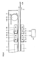
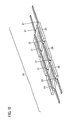
- a solar cell fabrication apparatus 1 includes a pair of lower belts 4a and 4b carrying a solar cell main body 20 and a tab lead 21 to convey the same in one direction.
- Lower belts 4a and 4b are formed of, for example, steel.
- the pair of lower belts 4a and 4b are wound around a drive roller 2a and a driven roller 3 a to be driven in the direction indicated by arrow 31 by drive roller 2a.
- stage unit 9 for receiving solar cell main body 20 and tab lead 21 is provided.
- Solar cell main body 20 and tab lead 21 are first mounted on lower belts 4a and 4b located above stage unit 9.
- solar cell main body 20 and tab lead 21 mounted on lower belts 4a and 4b are conveyed in a state secured to lower belts 4a and 4b by adsorption.
- a plurality of openings are formed along the transportation direction at lower belts 4a and 4b.
- a groove is formed at stage unit 9 located right below the openings. The groove extends along the openings.
- solar cell main body 20 and tab lead 21 is secured by adsorption to lower belts 4a and 4b via the openings.
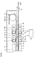
- a plurality of lower heater blocks 7 are provided to heat solar cell main body 20 and tab lead 21 that are conveyed from below.
- Lower heat block 7 is covered with a heat insulator 12 except for the side facing lower belts 4a and 4b.
- a heat conductive plate 10 is provided between lower heater block 7 and lower belts 4a and 4b.
- lower belts 4a and 4b are provided a pair of upper belts 5a and 5b to press solar cell main body 20 and tab lead 21 towards lower belt 4a and 4b.
- Upper belts 5a and 5b are formed of, for example, steel.
- the pair of upper belts 5a and 5b are wound around drive roller 2b (refer to Fig. 4) and a driven roller 3b to be driven in the direction indicated by arrow 32 in synchronization with the motion of lower belts 4a and 4b by drive roller 2b.
- the face of upper belts 5a and 5b forming contact with solar cell main body 20 and tab lead 21 is applied with a coating of, for example, Teflon (registered trademark) as a protection film to prevent attachment of flux.
- Teflon registered trademark
- upper belts 5a and 5b are provided a plurality of upper heater blocks 8a-8d to heat solar cell main body 20 and tab lead 21 that are conveyed from above.
- upper heater blocks 8a-8d are provided phosphor bronze plates 11 to apply an urging force against upper belts 5a and 5b towards lower belts 4a and 4b.
- upper heater block 8 is covered with heat insulator 12 except for the side that faces upper belts 5a and 5b.
- heat insulator 12 qualified as a furnace along the transportation direction.
- an inert gas supply unit 41 to supply inert gas such as nitrogen into the region surrounded by heat insulator 12.
- a plurality of lower cooling blocks 13 to cool solar cell main body 20 and tab lead 21 from below are provided at the downstream side of lower heater block 7 in the transportation direction.
- a heat conductive plate 10 is provided between lower cooling blocks 13a and 13b and lower belts 4a and 4b. Further, above lower belts 4a and 4b are provided a plurality of upper cooling blocks 14a and 14b to cool solar cell main body 20 and tab lead 21 from above, opposite to lower cooling block 13.
- Upper cooling blocks 14a and 14b are provided with phosphor bronze plates 11 to apply an urging force against upper belts 5a and 5b towards lower belts 4a and 4b.
- a coolant supply unit 42 to supply coolant to is provided.
- air holes 15 that open towards solar cell 20 and tab lead 21 are formed at upper cooling blocks 14a and 14b and lower cooling blocks 13a and 13b to cool down solar cell 20 and tab lead 21.
- a cleaning roller 16 to clean the face of upper belts 5a and 5b forming contact with solar cell main body 20 and tab lead 21 is provided in top cover 6.
- Solar cell main body 20 and tab lead 21 mounted on lower belts 4a and 4b are secured thereto by adsorption.
- solar cell main body 20 and tab lead 21 are conveyed towards the side where lower heat block 7 and upper heater block 8 are provided in a state maintaining the positioned relationship therebetween.
- Solar cell main body 20 and tab lead 21 located between lower belts 4a and 4b and upper belts 5a and 5b will be conveyed in the sandwiched state.
- solar cell main body 20 and tab lead 21 are heated from below by lower heater blocks 7a-7e, and heated from above by upper heater blocks 8a-8d.
- the plurality of lower heater blocks 7a-7e are each set to a predetermined temperature so as to obtain a desired temperature profile suitable for heating and melting solder to connect tab lead 21 to solar cell main body 20 in accordance with the transportation of solar cell main body 20 and tab lead 21.
- the plurality of upper heater blocks 8 are each set to a predetermined temperature corresponding to lower heat block 7.
- the temperature of solar cell main body 20 and tab lead 21 gradually rises, and the solder applied on tab lead 21 melts when arriving at the zone of the desired temperature.
- solar cell main body 20 and tab lead 21 are further conveyed to pass the zone attaining the desired temperature, solar cell main body 20 and tab lead 21 are then gradually cooled by lower cooling block 13 from below and by upper cooling block 14 from above, as shown in Fig. 9.
- the amount of coolant flowing to lower cooling block 13 by coolant supply unit 42 is adjusted so as to obtain the desired temperature profile suitable for solidification of the melting solder to connect tab lead 21 to solar cell main body 20 according to the transportation of solar cell main body 20 and tab lead 21.
- the amount of coolant flowing to upper cooling block 14 is adjusted corresponding to lower cooling block 13, at the plurality of upper cooling blocks 14.
- the temperature of solar cell main body 20 and tab lead 21 gradually drops according to the transportation of solar cell main body 20 and tab lead 21.
- the melting solder is solidified to provide connection between tab lead 21 and solar cell main body 20.
- upper belts 5a and 5b are wound around drive roller 2b such that solar cell main body 20 and tab lead 21 are released from the sandwiched state between lower belts 4a and 4b and upper belts 5a and 5b.
- solar cell 22 having tab lead 21 soldered to solar cell main body 20 is taken out from lower belts 4a and 4b.
- Solar cell 22 is delivered to the next step to be sealed between a glass substrate and a back film by predetermined resin.
- the entirety of solar cell main body 20 and tab lead 21 will be pressed appropriately by the weight of upper belts 5a and 5b and the elasticity of phosphor bronze plate 11.
- the elasticity of phosphor bronze plate 11 qualified as an elastic member can be altered according to the configuration of the solar cell and tab lead to be fabricated. Therefore, the solar cell and tab lead can be pressed more appropriately to ensure that generation of strain at solar cell main body 20 is suppressed.
- tab lead 121 is pressed locally against solar cell main body 120 by pressing rod 112 as in a conventional solar cell fabrication apparatus 101
- the entirety of tab lead 21 is pressed by upper belts 5a and 5b. Therefore, the surface of the solder is flat all over tab lead 21 without any generation of a protruding solder.
- the problem of the solar cell main body being damaged by the contact of the tip of the protruding solder with the glass substrate can be prevented.
- the yield of the solar cell can be improved.
- Conventional solar cell fabrication apparatus 101 is disadvantageous in that, when the size of the solar cell main body is to be altered, the interval of pressing rods 112 attached to endless belt 111 has to be modified in accordance with the size of the solar cell main body.
- solar cell fabrication apparatus 1 does not require this labor when the size of the solar cell main body is to be altered since the entirety of solar cell main body 20 and tab lid 21 is pressed by upper belts 5a and 5b.
- phosphor bronze plate 11 between upper belts 5a and 5b and upper heater block 8 prevents abrasion of upper heater block 8 in association with the drive of upper belts 5a and 5b.
- the face of upper belts 5a and 5b that is brought into contact with solar cell main body 20 and tab lead 21 has a protection film such as Teflon (registered trademark) formed to prevent flux attachment.
- flux can be removed, even if it is attached to the surface of upper belts 5a and 5b, at a relatively initial stage by cleaning roller 16. Therefore, gradual accumulation of flux can be prevented, and the maintenance property can be improved.
- Solar cell fabrication apparatus 1 has upper and lower heater blocks 8 and 7 surrounded by a heat insulator 12 qualified as a furnace along the transportation direction. Solar cell main body 20 and tab lead 21 are conveyed between upper heater blocks 8a-8d and lower heater blocks 7a-7e.
- the entirety of solar cell main body 20 is heated at solar cell fabrication apparatus 1. Therefore, generation of heat strain at solar cell main body 20 can be reduced. As a result, the yield of the solar cell can be improved.
- upper heater block 8 and lower heater block 7 a plurality of upper heater blocks 8a-8d and lower heater blocks 7a-7e are provided.
- upper and lower heater blocks 8 and 7 at the inner side of heat insulator 12 qualified as a furnace suppresses the escape of heat radiation to ensure a relatively high thermal efficiency. This leads to a saving of power consumption, contributing to saving energy.
- inert gas introduction of inert gas into the region surrounded by heat insulator 12 allows this region to be maintained in inert gas atmosphere. Therefore, formation of an oxide film on the surface of solder is suppressed and solder wettability is improved. As a result, tab lead 21 can be reliably connected to solar cell main body 20.
- upper cooling block 14 and lower cooling block 13 at solar cell fabrication apparatus 1 a plurality of upper cooling blocks 14a and 14b and lower cooling blocks 13a and 13b, respectively, are provided. Coolant is supplied by coolant supply unit 42 to upper cooling blocks 14a and 14b and lower cooling blocks 13a and 13b.
- each of upper cooling blocks 14a and 14b and lower cooling blocks 13a and 13b can be conducted relatively easily by adjusting the amount of coolant.
- phosphor bronze plate 11 was taken as an example for an elastic member applying urging force against upper belts 5a and 5b towards lower belts 4a and 4b.
- the resilient member is not limited to a phosphor bronze plate. Any of a material that can apply the urging force set forth above and prevent abrasion of upper heater block 8 with respect to the movement of upper belts 5a and 5b may be used.
- Teflon (registered trademark) coating was taken as an example of a protection film formed on the plane of upper belts 5a and 5b that is to be brought into contact with solar cell main body 20 and tab lead 21.
- the protection film is not limited to Teflon (registered trademark) coating, and any that can prevent flux attachment may be employed.
- the present invention is effectively applicable to soldering a tab lead to a solar cell main body.
Landscapes
- Photovoltaic Devices (AREA)
Applications Claiming Priority (1)
| Application Number | Priority Date | Filing Date | Title |
|---|---|---|---|
| PCT/JP2004/007806 WO2005117140A1 (ja) | 2004-05-28 | 2004-05-28 | 太陽電池セル製造装置 |
Publications (2)
| Publication Number | Publication Date |
|---|---|
| EP1783837A1 true EP1783837A1 (de) | 2007-05-09 |
| EP1783837A4 EP1783837A4 (de) | 2007-09-26 |
Family
ID=35451162
Family Applications (1)
| Application Number | Title | Priority Date | Filing Date |
|---|---|---|---|
| EP04735408A Withdrawn EP1783837A4 (de) | 2004-05-28 | 2004-05-28 | Vorrichtung zur herstellung von solarbatteriezellen |
Country Status (3)
| Country | Link |
|---|---|
| US (1) | US20080061111A1 (de) |
| EP (1) | EP1783837A4 (de) |
| WO (1) | WO2005117140A1 (de) |
Cited By (3)
| Publication number | Priority date | Publication date | Assignee | Title |
|---|---|---|---|---|
| EP1699090A4 (de) * | 2003-12-25 | 2011-09-07 | Sharp Kk | Verfahren und vorrichtung zur herstellung eines solarbatteriemoduls |
| WO2012100958A1 (en) * | 2011-01-28 | 2012-08-02 | Centrotherm Thermal Solutions Gmbh & Co. Kg | Cooling module and apparatus for thermally treating substrates |
| EP2634818A4 (de) * | 2010-10-26 | 2016-04-27 | Panasonic Ip Man Co Ltd | Verfahren zur herstellung eines solarzellenmoduls |
Families Citing this family (22)
| Publication number | Priority date | Publication date | Assignee | Title |
|---|---|---|---|---|
| JP4903021B2 (ja) | 2006-08-28 | 2012-03-21 | 株式会社エヌ・ピー・シー | タブリードのはんだ付け装置およびはんだ付け方法 |
| DE102008037403A1 (de) * | 2008-09-30 | 2010-04-01 | Jörg NIEMEIER | Verfahren und Vorrichtung zum Verbinden einer Solarzelle mit einem Zellverbinder |
| ES2378017T3 (es) * | 2009-12-22 | 2012-04-04 | Kioto Photovoltaics Gmbh | Dispositivo para fijar pistas conductoras sobre una célula solar |
| US8231044B2 (en) | 2010-10-01 | 2012-07-31 | Orthodyne Electronics Corporation | Solar substrate ribbon bonding system |
| JP5091296B2 (ja) * | 2010-10-18 | 2012-12-05 | 東京エレクトロン株式会社 | 接合装置 |
| JP2013026611A (ja) * | 2011-07-26 | 2013-02-04 | Sanyo Electric Co Ltd | 太陽電池モジュールの製造方法 |
| US8328077B1 (en) * | 2011-11-01 | 2012-12-11 | Flextronics Ap, Llc | PV cell mass reflow |
| JP2014011231A (ja) * | 2012-06-28 | 2014-01-20 | Hitachi Ltd | ハンダボール印刷搭載装置 |
| US9243726B2 (en) | 2012-10-03 | 2016-01-26 | Aarne H. Reid | Vacuum insulated structure with end fitting and method of making same |
| US9601651B2 (en) * | 2013-06-21 | 2017-03-21 | Muehlbauer GmbH & Co. KG | Method and apparatus for manufacturing a solar module strand and a solar module strand of flexible solar cells |
| US9463918B2 (en) | 2014-02-20 | 2016-10-11 | Aarne H. Reid | Vacuum insulated articles and methods of making same |
| WO2016063244A1 (en) | 2014-10-24 | 2016-04-28 | Somont Gmbh | Interconnecting device and method |
| US10497908B2 (en) | 2015-08-24 | 2019-12-03 | Concept Group, Llc | Sealed packages for electronic and energy storage devices |
| US10065256B2 (en) * | 2015-10-30 | 2018-09-04 | Concept Group Llc | Brazing systems and methods |
| EP3423854A4 (de) | 2016-03-04 | 2020-01-01 | Concept Group LLC | Vakuumisolierte artikel mit verbesserung des reflektierenden materials |
| EP3276655A1 (de) * | 2016-07-26 | 2018-01-31 | Nederlandse Organisatie voor toegepast- natuurwetenschappelijk onderzoek TNO | Verfahren und system zum verbinden eines chips mit einem substrat |
| US11008153B2 (en) | 2016-11-15 | 2021-05-18 | Concept Group Llp | Multiply-insulated assemblies |
| MX2019005662A (es) | 2016-11-15 | 2019-11-21 | Concept Group Llc | Artículos mejorados aislados al vacío con aislamiento microporoso. |
| CN106684454A (zh) * | 2016-12-26 | 2017-05-17 | 广东利迅达机器人系统股份有限公司 | 一种具有在线冷却功能的电池输送线 |
| JP2020531764A (ja) | 2017-08-25 | 2020-11-05 | コンセプト グループ エルエルシー | 複合的ジオメトリおよび複合的材料の断熱部品 |
| CN113851737B (zh) * | 2021-08-26 | 2023-08-04 | 合肥国轩高科动力能源有限公司 | 一种圆柱锂离子电池制造方法 |
| KR20250129378A (ko) * | 2024-02-22 | 2025-08-29 | 한화솔루션 주식회사 | 가압 장치 및 이를 포함하는 태빙 장치 |
Family Cites Families (28)
| Publication number | Priority date | Publication date | Assignee | Title |
|---|---|---|---|---|
| US3185604A (en) * | 1962-04-12 | 1965-05-25 | Gen Foods Corp | Method of forming a scouring article |
| US3283523A (en) * | 1963-12-30 | 1966-11-08 | Swift & Co | Method and apparatus for processing filled containers |
| US3462001A (en) * | 1967-05-26 | 1969-08-19 | Fmc Corp | Container orienting apparatus |
| US3684645A (en) * | 1969-03-25 | 1972-08-15 | Ppg Industries Inc | Glass fiber reinforced thermoplastic article |
| US3923206A (en) * | 1972-11-16 | 1975-12-02 | Stanhay Ashford Ltd | Seed separator with adjustment for different seed sizes |
| US4139613A (en) * | 1975-07-23 | 1979-02-13 | Kufner Textilwerke Kg | Process for the patterned deposition of powdered thermoplastic adhesive materials on the outer surface of a surface form |
| US4450033A (en) * | 1981-10-13 | 1984-05-22 | Spire Corp. | Front surface metallization and encapsulation of solar cells |
| US4430519A (en) * | 1982-05-28 | 1984-02-07 | Amp Incorporated | Electron beam welded photovoltaic cell interconnections |
| DE3238187C2 (de) * | 1982-10-15 | 1984-08-09 | Messerschmitt-Bölkow-Blohm GmbH, 8000 München | Verfahren zum Herstellen von Solargeneratoren |
| US4534502A (en) * | 1983-02-14 | 1985-08-13 | Atlantic Richfield Company | Automatic solder machine |
| US4888039A (en) * | 1985-05-10 | 1989-12-19 | Emerson Electric Co. | Apparatus for manufacturing hermetic terminal assemblies |
| US4888082A (en) * | 1986-10-31 | 1989-12-19 | Nordson Corporation | Apparatus for adhesive transfer |
| DE3819027A1 (de) * | 1988-06-03 | 1989-12-14 | Meyer Herbert Gmbh Co Kg | Verfahren und anordnung zum verkleben flaechiger werkstuecke |
| EP0540797A1 (de) * | 1991-11-07 | 1993-05-12 | Paul Leon | Maschine zum Reihen und Löten einer Mehrzahl von Halbleitervorrichtungen mit den Verbindungsleitern |
| US5679155A (en) * | 1992-03-16 | 1997-10-21 | Velie Circuits, Inc. | Method and apparatus for soldering circuit boards |
| CA2120111C (en) * | 1993-04-26 | 2002-06-11 | F. Arthur Simmons | Method of applying adhesive to porous materials |
| EP0655976B1 (de) * | 1993-06-11 | 1999-01-13 | ISOVOLTAÖsterreichische IsolierstoffwerkeAktiengesellschaft | Verfahren zur herstellung fotovoltaischer module sowie eine vorrichtung zur durchführung dieses verfahrens |
| US5364007A (en) * | 1993-10-12 | 1994-11-15 | Air Products And Chemicals, Inc. | Inert gas delivery for reflow solder furnaces |
| DE4404287A1 (de) * | 1994-02-11 | 1995-08-17 | Focke & Co | Vorrichtung zum Herstellen von Zuschnitten für Kragen in Klappschachteln mit abgerundeten oder mehreckigen Längskanten |
| EP0749636A1 (de) * | 1994-12-01 | 1996-12-27 | Angewandte Solarenergie - ASE GmbH | Verfahren und apparat zum zusammenschalten von solarzellen |
| US6068715A (en) * | 1995-06-07 | 2000-05-30 | Ube-Nitto Kasei Co., Ltd. | Glass fiber mat for stampable sheet, process for the production of the mat, stampable sheet made from said mat, process for the production of the sheet, and equipment for the production thereof |
| US5617989A (en) * | 1995-07-25 | 1997-04-08 | Kelzer; Robert A. | Solder leveling apparatus and method |
| DE19627225A1 (de) * | 1996-07-05 | 1998-01-08 | Focke & Co | Verfahren und Vorrichtung zum opto-elektrischen Abtasten von Verpackungen, insbesondere Zigaretten-Packungen |
| US6152068A (en) * | 1998-06-22 | 2000-11-28 | Hunter Douglas Inc. | Apparatus for manufacturing an adjustable covering for architectural openings |
| JP4240587B2 (ja) * | 1998-07-03 | 2009-03-18 | 株式会社エヌ・ピー・シー | タブリードのはんだ付け装置 |
| US6342115B1 (en) * | 1999-08-18 | 2002-01-29 | Nasser Pourmand | Laminating heating module |
| JP3948946B2 (ja) * | 2001-11-30 | 2007-07-25 | 三洋電機株式会社 | タブリードの半田付け方法と半田付け装置 |
| JP3609803B2 (ja) * | 2002-07-03 | 2005-01-12 | トヤマキカイ株式会社 | リードの溶着装置 |
-
2004
- 2004-05-28 EP EP04735408A patent/EP1783837A4/de not_active Withdrawn
- 2004-05-28 WO PCT/JP2004/007806 patent/WO2005117140A1/ja not_active Ceased
- 2004-05-28 US US11/597,562 patent/US20080061111A1/en not_active Abandoned
Non-Patent Citations (2)
| Title |
|---|
| No further relevant documents disclosed * |
| See also references of WO2005117140A1 * |
Cited By (6)
| Publication number | Priority date | Publication date | Assignee | Title |
|---|---|---|---|---|
| EP1699090A4 (de) * | 2003-12-25 | 2011-09-07 | Sharp Kk | Verfahren und vorrichtung zur herstellung eines solarbatteriemoduls |
| US8152044B2 (en) | 2003-12-25 | 2012-04-10 | Sharp Kabushiki Kaisha | Solar battery module production method and solar battery module production apparatus |
| EP2634818A4 (de) * | 2010-10-26 | 2016-04-27 | Panasonic Ip Man Co Ltd | Verfahren zur herstellung eines solarzellenmoduls |
| WO2012100958A1 (en) * | 2011-01-28 | 2012-08-02 | Centrotherm Thermal Solutions Gmbh & Co. Kg | Cooling module and apparatus for thermally treating substrates |
| US20130299130A1 (en) * | 2011-01-28 | 2013-11-14 | Centrotherm Thermal Solutions Gmbh & Co Kg | Cooling module and apparatus for thermally treating substrates |
| US10082346B2 (en) * | 2011-01-28 | 2018-09-25 | centrotherm international AG | Cooling module and apparatus for thermally treating substrates |
Also Published As
| Publication number | Publication date |
|---|---|
| EP1783837A4 (de) | 2007-09-26 |
| WO2005117140A1 (ja) | 2005-12-08 |
| US20080061111A1 (en) | 2008-03-13 |
Similar Documents
| Publication | Publication Date | Title |
|---|---|---|
| EP1783837A1 (de) | Vorrichtung zur herstellung von solarbatteriezellen | |
| JP4248389B2 (ja) | 太陽電池モジュールの製造方法と太陽電池モジュールの製造装置 | |
| CN1578600B (zh) | 部件接合装置及方法与部件安装装置 | |
| JP2000022188A (ja) | タブリードのはんだ付け装置 | |
| CN101820000B (zh) | 太阳能电池引线及其制造方法和使用该引线的太阳能电池 | |
| US20110163085A1 (en) | Method for Soldering Contact Wires to Solar Cells | |
| US20120131959A1 (en) | Laser sealing device for glass substrates | |
| JP3786091B2 (ja) | 電子デバイス製造装置、電子デバイスの製造方法および電子デバイスの製造プログラム | |
| CN101281937A (zh) | 接合导线向太阳能电池单元的软钎焊方法 | |
| JP4527945B2 (ja) | 太陽電池セル製造装置 | |
| CN100382261C (zh) | 电荷发生半导体基板用凸起形成装置、电荷发生半导体基板的除静电方法、电荷发生半导体基板用除静电装置、及电荷发生半导体基板 | |
| WO2007080822A1 (ja) | 太陽電池素子の接続方法及び接続装置 | |
| JP4838787B2 (ja) | 太陽電池素子の接続方法及び太陽電池素子の接続装置 | |
| JP3609803B2 (ja) | リードの溶着装置 | |
| JP6815678B1 (ja) | 電子部品のシンタリング装置および方法 | |
| US20030221853A1 (en) | Apparatus for manufacturing electronic device, method of manufacturing electronic device, and program for manufacturing electronic device | |
| TW200402810A (en) | Manufacturing apparatus of electronic device, manufacturing method of electronic device, and manufacturing program of electronic device | |
| JP4302037B2 (ja) | 太陽電池モジュールの製造方法と太陽電池モジュールの製造装置 | |
| CN119016833B (zh) | 太阳能电池的焊接方法和太阳能电池 | |
| CN221158899U (zh) | 焊料预熔装置、焊接设备、电池串、电池组件及光伏系统 | |
| JP2007273830A (ja) | 太陽電池装置の製造方法 | |
| CN212917975U (zh) | 太阳能电池组件的加工设备 | |
| JP4378340B2 (ja) | 太陽電池素子の接続方法 | |
| CN118559140A (zh) | 焊料预熔装置、焊接设备、方法、电池串及电池组件 | |
| JP2011146482A (ja) | 太陽電池モジュールの製造装置及び太陽電池モジュールの製造方法 |
Legal Events
| Date | Code | Title | Description |
|---|---|---|---|
| PUAI | Public reference made under article 153(3) epc to a published international application that has entered the european phase |
Free format text: ORIGINAL CODE: 0009012 |
|
| 17P | Request for examination filed |
Effective date: 20061219 |
|
| AK | Designated contracting states |
Kind code of ref document: A1 Designated state(s): DE ES GB IT |
|
| DAX | Request for extension of the european patent (deleted) | ||
| RBV | Designated contracting states (corrected) |
Designated state(s): DE ES GB IT |
|
| A4 | Supplementary search report drawn up and despatched |
Effective date: 20070824 |
|
| 17Q | First examination report despatched |
Effective date: 20090223 |
|
| STAA | Information on the status of an ep patent application or granted ep patent |
Free format text: STATUS: THE APPLICATION IS DEEMED TO BE WITHDRAWN |
|
| 18D | Application deemed to be withdrawn |
Effective date: 20090707 |