EP1783877A2 - Système de transmission pour la transmission haute puissance à bas champ magnétique - Google Patents
Système de transmission pour la transmission haute puissance à bas champ magnétique Download PDFInfo
- Publication number
- EP1783877A2 EP1783877A2 EP06017898A EP06017898A EP1783877A2 EP 1783877 A2 EP1783877 A2 EP 1783877A2 EP 06017898 A EP06017898 A EP 06017898A EP 06017898 A EP06017898 A EP 06017898A EP 1783877 A2 EP1783877 A2 EP 1783877A2
- Authority
- EP
- European Patent Office
- Prior art keywords
- phase
- cable
- transmission
- transmission system
- transformer
- Prior art date
- Legal status (The legal status is an assumption and is not a legal conclusion. Google has not performed a legal analysis and makes no representation as to the accuracy of the status listed.)
- Granted
Links
Images


Classifications
-
- H—ELECTRICITY
- H02—GENERATION; CONVERSION OR DISTRIBUTION OF ELECTRIC POWER
- H02G—INSTALLATION OF ELECTRIC CABLES OR LINES, OR OF COMBINED OPTICAL AND ELECTRIC CABLES OR LINES
- H02G15/00—Cable fittings
- H02G15/08—Cable junctions
- H02G15/10—Cable junctions protected by boxes, e.g. by distribution, connection or junction boxes
- H02G15/103—Cable junctions protected by boxes, e.g. by distribution, connection or junction boxes with devices for relieving electrical stress
- H02G15/105—Cable junctions protected by boxes, e.g. by distribution, connection or junction boxes with devices for relieving electrical stress connected to the cable shield only
- H02G15/1055—Cable junctions protected by boxes, e.g. by distribution, connection or junction boxes with devices for relieving electrical stress connected to the cable shield only with cross-bonding of cable shields
-
- H—ELECTRICITY
- H01—ELECTRIC ELEMENTS
- H01B—CABLES; CONDUCTORS; INSULATORS; SELECTION OF MATERIALS FOR THEIR CONDUCTIVE, INSULATING OR DIELECTRIC PROPERTIES
- H01B9/00—Power cables
- H01B9/02—Power cables with screens or conductive layers, e.g. for avoiding large potential gradients
- H01B9/029—Screen interconnecting circuits
Definitions
- the invention relates to a cable system that allows the underground transmission of high power at very low magnetic fields.
- the cable cores are usually laid with corresponding clear distances in one plane.
- the magnetic fields occurring here can be significant. Assuming, for example, a center distance of the cable cores of 0.5 m and a transfer current of 2000 A, results in 1.2 m depth of immersion, a magnetic induction above the middle cable core in 0.2 m height above the ground of approx. 160 ⁇ T (the legal limit is 100 ⁇ T in Germany, 1 ⁇ T in Switzerland and already 0.2 ⁇ T in some regions of Italy),
- a shielding of the individual cable core with magnetic material is not possible.
- a shielding of the single core with a highly conductive shell (Cu, Al) is very complex, technically problematic and associated with high losses due to longitudinal currents.
- the invention is therefore based on the object to provide a magnetic field poor transmission system for very high performance.
- the object is achieved by the transmission system having the features of claim 1.
- the subclaims indicate advantageous embodiments of the invention.
- the subclaims specify alternative circuits in the case of differently configured fault cases, which also offer the possibility of a successive construction of the transmission system according to the invention.
- the voltages to be transmitted by the transmission system and out of phase in each transmission line are preferably obtained by feeding two three-phase transformers whose secondary windings have opposite winding directions in parallel into the cables.
- a three-phase supply transformer may be used whose secondary windings each have a center tap.
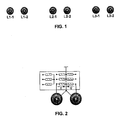
- Fig. 1 shows six cable cores of the transmission system, of which two cable cores are arranged close to each other.
- the alternating voltages in the two cable cores of a pair are offset from one another by 180 °.
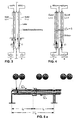
- Fig. 2 shows a feeding transformer, the secondary windings each having a center tap, as is common in power converter transformers.
- Fig. 3 shows the closely spaced cable cores of the phases L1-1 and L1-2, starting from the two transformer secondary windings. It can be seen that the load current I in the conductor of the first cable core (L1-1) led to the consumer and in the head of the second cable core (L1-2) is returned from there. At the opposite end is also the consumer with center tap accordingly to switch. The easiest way to do this is to use one or two transformers of the same type as the infeed side.
- the three-phase phases consisting of the cables L1-1 / L1-2 etc., are magnetically decoupled from each other.
- the low inductance which is determined by the conductor spacing between two adjacent cable cores (such as the cable diameter), is decisive as line longitudinal inductance for the transmission behavior.
- the center potential (center tap) of the three-winding supply transformer is to be connected and grounded to the cable shields or sheaths of the cable cores. If one moves on both sides of the transmission system in this way, longitudinal currents are induced in the cable shields (or shrouds, ff.) Grounded on both sides, which are directed counter to the respective conductor currents.
- the cable shields can be made normal and shield losses can be suppressed if main sections are formed along the transmission path, in the middle of which the two channels of two adjacent cable cores are interrupted and the two screen sections of one core are insulated from one another, in order to connect the first screen section of one cable core to the second Umbrella portion of the adjacent cable core to electrically connect, as shown in FIG. 4th is shown for a main section. At the ends of the main section, the two channels are shorted together and grounded if necessary.
- the shield circuit described corresponds in principle to the known cyclic cross-bonding of three-phase cables, in which the main section is divided into three and the screen sections are interconnected at the two outcrossing points. Incidentally, these outcrossing sleeves must be protected by surge arresters.
- phase currents of two adjacent cable cores always complement each other to zero. Therefore, in each case two adjacent cable cores with a magnetic shell, such as a steel tube, are surrounded, so that their already low magnetic field can be reduced to a vanishing degree anyway.
- This principle works - in contrast to a bundled three-phase system in a magnetic envelope - even if the feeding three-phase system is unbalanced and a zero current leads.
- a transmission system is presented in which, in the six-phase variant, six HVAC cable cores are fed by two three-phase systems in phase opposition, ie by a six-phase system.
- These "bipolar operated three-phase systems” offer the possibility for submarine cables to lay close to each other two submarine cables with a laying process, which have as a respective alternating current system with forward and return conductor (zero current sum) a vanishingly small magnetic field.
- the three cable routes or transmission lines are thus decoupled from each other electromagnetically.
- the additional expense consists initially in that an additional power transformer or a three-winding transformer is to be provided at both ends of the transmission path, as is known in the converter technology or in the traction power supply.
- compensation devices must be provided for a compensation capacity that is twice as high as in a single three-phase system.
- converters of the feeding power plants for example also wind power plants
- converters of the feeding power plants with their wide, controllable operating range could be used to at least partially provide the second three-phase current system in phase opposition and / or b) the required compensation power on the offshore side.
- the reinforcements of the individual cores must be non-magnetic. At intervals of a few kilometers, a galvanic contact between the armatures of two adjacent cable cores must be made, so that the capacitive and dielectric cross currents of the two cores can complement each other to zero and do not have to be transported via the lead sheaths. This can be done according to Fig. 5b with the aid of factory-made anti-corrosion sleeves, with which a contacted with the conductive PE sheath and the armor conductor is led out of the wire and connected during the installation process via a compensating cable with the second, just prepared cable core.
Landscapes
- Cable Transmission Systems, Equalization Of Radio And Reduction Of Echo (AREA)
- Power Conversion In General (AREA)
- Near-Field Transmission Systems (AREA)
- Laying Of Electric Cables Or Lines Outside (AREA)
Applications Claiming Priority (1)
| Application Number | Priority Date | Filing Date | Title |
|---|---|---|---|
| DE102005052840 | 2005-11-05 |
Publications (3)
| Publication Number | Publication Date |
|---|---|
| EP1783877A2 true EP1783877A2 (fr) | 2007-05-09 |
| EP1783877A3 EP1783877A3 (fr) | 2008-08-06 |
| EP1783877B1 EP1783877B1 (fr) | 2009-07-01 |
Family
ID=37691786
Family Applications (1)
| Application Number | Title | Priority Date | Filing Date |
|---|---|---|---|
| EP06017898A Not-in-force EP1783877B1 (fr) | 2005-11-05 | 2006-08-28 | Système de transmission pour la transmission haute puissance à bas champ magnétique |
Country Status (4)
| Country | Link |
|---|---|
| EP (1) | EP1783877B1 (fr) |
| AT (1) | ATE435511T1 (fr) |
| DE (1) | DE502006004117D1 (fr) |
| ES (1) | ES2329277T3 (fr) |
Cited By (2)
| Publication number | Priority date | Publication date | Assignee | Title |
|---|---|---|---|---|
| DE102009024149A1 (de) * | 2009-06-06 | 2011-06-16 | Nkt Cables Gmbh | Einadriges Drehstromkabel mit integrierter elektromagnetischer Schirmung |
| EP2259271A3 (fr) * | 2009-06-06 | 2012-06-20 | nkt cables GmbH | Système triphasé haute tension et câble triphasé mono-conducteur doté d'un blindage pour le système |
Family Cites Families (2)
| Publication number | Priority date | Publication date | Assignee | Title |
|---|---|---|---|---|
| GB2106306B (en) * | 1981-07-28 | 1985-07-31 | Pirelli General Plc | Improvements in electric cables and installations |
| DE19512018C1 (de) * | 1995-03-31 | 1996-04-11 | Felten & Guilleaume Energie | Schaltungsanordnung für Drehstromkabel |
-
2006
- 2006-08-28 AT AT06017898T patent/ATE435511T1/de not_active IP Right Cessation
- 2006-08-28 EP EP06017898A patent/EP1783877B1/fr not_active Not-in-force
- 2006-08-28 ES ES06017898T patent/ES2329277T3/es active Active
- 2006-08-28 DE DE502006004117T patent/DE502006004117D1/de active Active
Cited By (2)
| Publication number | Priority date | Publication date | Assignee | Title |
|---|---|---|---|---|
| DE102009024149A1 (de) * | 2009-06-06 | 2011-06-16 | Nkt Cables Gmbh | Einadriges Drehstromkabel mit integrierter elektromagnetischer Schirmung |
| EP2259271A3 (fr) * | 2009-06-06 | 2012-06-20 | nkt cables GmbH | Système triphasé haute tension et câble triphasé mono-conducteur doté d'un blindage pour le système |
Also Published As
| Publication number | Publication date |
|---|---|
| ATE435511T1 (de) | 2009-07-15 |
| DE502006004117D1 (de) | 2009-08-13 |
| ES2329277T3 (es) | 2009-11-24 |
| EP1783877B1 (fr) | 2009-07-01 |
| EP1783877A3 (fr) | 2008-08-06 |
Similar Documents
| Publication | Publication Date | Title |
|---|---|---|
| DE102011013330B3 (de) | Einphasige Speiseanordnung und Verfahren zur Versorgung einer Fahrleitung einer Wechselstrombahn mit Einphasenwechselstrom | |
| EP3751692B1 (fr) | Station de transmission de courant continu à haute tension | |
| EP1783877B1 (fr) | Système de transmission pour la transmission haute puissance à bas champ magnétique | |
| AT509837B1 (de) | Vorrichtung zur fehlerstromreduktion | |
| WO2018153433A1 (fr) | Convertisseur de puissance modulaire à plusieurs niveaux | |
| EP2246948B1 (fr) | Agencement de compensation de champ magnétique dans des câbles à courant fort | |
| EP3161930B1 (fr) | Montage pour connecter une alimentation électrique de voie destinée à une voie, à un réseau d'alimentation triphasé | |
| DE2018981C3 (de) | Mehrphasiger Generator | |
| DE102011100983B4 (de) | Verbinderanordnung für Mittelspannungsanlagen | |
| DE102012021936B4 (de) | Schaltbare Kurzschlussverbinder einer Mittelspannungsanlage | |
| EP0883138A2 (fr) | Ligne de câble pour transporter de hautes puissances | |
| EP3139392B1 (fr) | Transformateur a frequence moyenne et convertisseur a semi-conducteur ayant un transformateur a frequence moyenne | |
| EP3900141B1 (fr) | Procédé et dispositif pour un réseau à courant alternatif à débit de puissance accru | |
| WO2013060617A1 (fr) | Appareil de commutation à haute tension comprenant un dispositif d'alimentation en énergie | |
| WO2009138099A1 (fr) | Connexion de modules d'enroulements de transformateur | |
| DE313389C (fr) | ||
| DE102018006788A1 (de) | Windenergieanlage mit verbessertem Störverhalten | |
| DE210509C (fr) | ||
| DE729682C (de) | Anordnung zur UEbertragung von Drehstromleistung auf grosse Entfernungen | |
| DE102007019164A1 (de) | Transformatorenschaltung | |
| EP3382842B1 (fr) | Éolienne dotée du transformateur d'installation à courant de court-circuit renforcé | |
| DE3410726A1 (de) | Einphasiges metallgekapseltes wechselstromsystem | |
| DE102022124365A1 (de) | Elektrisches Netzwerk zur Hochspannungsgleichstromübertragung | |
| EP4089696A1 (fr) | Bobine électrique agencée dans un champ électromagnétique alternatif permettant de générer du courant destiné à un usage propre | |
| DE19843100B4 (de) | Drehstromkabel |
Legal Events
| Date | Code | Title | Description |
|---|---|---|---|
| PUAI | Public reference made under article 153(3) epc to a published international application that has entered the european phase |
Free format text: ORIGINAL CODE: 0009012 |
|
| AK | Designated contracting states |
Kind code of ref document: A2 Designated state(s): AT BE BG CH CY CZ DE DK EE ES FI FR GB GR HU IE IS IT LI LT LU LV MC NL PL PT RO SE SI SK TR |
|
| AX | Request for extension of the european patent |
Extension state: AL BA HR MK YU |
|
| PUAL | Search report despatched |
Free format text: ORIGINAL CODE: 0009013 |
|
| AK | Designated contracting states |
Kind code of ref document: A3 Designated state(s): AT BE BG CH CY CZ DE DK EE ES FI FR GB GR HU IE IS IT LI LT LU LV MC NL PL PT RO SE SI SK TR |
|
| AX | Request for extension of the european patent |
Extension state: AL BA HR MK RS |
|
| 17P | Request for examination filed |
Effective date: 20080726 |
|
| GRAP | Despatch of communication of intention to grant a patent |
Free format text: ORIGINAL CODE: EPIDOSNIGR1 |
|
| AKX | Designation fees paid |
Designated state(s): AT BE BG CH CY CZ DE DK EE ES FI FR GB GR HU IE IS IT LI LT LU LV MC NL PL PT RO SE SI SK TR |
|
| GRAS | Grant fee paid |
Free format text: ORIGINAL CODE: EPIDOSNIGR3 |
|
| GRAA | (expected) grant |
Free format text: ORIGINAL CODE: 0009210 |
|
| AK | Designated contracting states |
Kind code of ref document: B1 Designated state(s): AT BE BG CH CY CZ DE DK EE ES FI FR GB GR HU IE IS IT LI LT LU LV MC NL PL PT RO SE SI SK TR |
|
| REG | Reference to a national code |
Ref country code: GB Ref legal event code: FG4D Free format text: NOT ENGLISH |
|
| REG | Reference to a national code |
Ref country code: CH Ref legal event code: EP |
|
| REG | Reference to a national code |
Ref country code: IE Ref legal event code: FG4D |
|
| REF | Corresponds to: |
Ref document number: 502006004117 Country of ref document: DE Date of ref document: 20090813 Kind code of ref document: P |
|
| RAP2 | Party data changed (patent owner data changed or rights of a patent transferred) |
Owner name: GEO GESELLSCHAFT FUER ENERGIE UND OEKOLOGIE MBH |
|
| NLT2 | Nl: modifications (of names), taken from the european patent patent bulletin |
Owner name: GEO GESELLSCHAFT FUER ENERGIE UND OEKOLOGIE MBH Effective date: 20090909 |
|
| REG | Reference to a national code |
Ref country code: ES Ref legal event code: FG2A Ref document number: 2329277 Country of ref document: ES Kind code of ref document: T3 |
|
| PG25 | Lapsed in a contracting state [announced via postgrant information from national office to epo] |
Ref country code: SI Free format text: LAPSE BECAUSE OF FAILURE TO SUBMIT A TRANSLATION OF THE DESCRIPTION OR TO PAY THE FEE WITHIN THE PRESCRIBED TIME-LIMIT Effective date: 20090701 |
|
| NLV1 | Nl: lapsed or annulled due to failure to fulfill the requirements of art. 29p and 29m of the patents act | ||
| PG25 | Lapsed in a contracting state [announced via postgrant information from national office to epo] |
Ref country code: LT Free format text: LAPSE BECAUSE OF FAILURE TO SUBMIT A TRANSLATION OF THE DESCRIPTION OR TO PAY THE FEE WITHIN THE PRESCRIBED TIME-LIMIT Effective date: 20090701 Ref country code: SE Free format text: LAPSE BECAUSE OF FAILURE TO SUBMIT A TRANSLATION OF THE DESCRIPTION OR TO PAY THE FEE WITHIN THE PRESCRIBED TIME-LIMIT Effective date: 20090701 Ref country code: EE Free format text: LAPSE BECAUSE OF FAILURE TO SUBMIT A TRANSLATION OF THE DESCRIPTION OR TO PAY THE FEE WITHIN THE PRESCRIBED TIME-LIMIT Effective date: 20090701 Ref country code: FI Free format text: LAPSE BECAUSE OF FAILURE TO SUBMIT A TRANSLATION OF THE DESCRIPTION OR TO PAY THE FEE WITHIN THE PRESCRIBED TIME-LIMIT Effective date: 20090701 Ref country code: IS Free format text: LAPSE BECAUSE OF FAILURE TO SUBMIT A TRANSLATION OF THE DESCRIPTION OR TO PAY THE FEE WITHIN THE PRESCRIBED TIME-LIMIT Effective date: 20091101 |
|
| REG | Reference to a national code |
Ref country code: IE Ref legal event code: FD4D |
|
| PG25 | Lapsed in a contracting state [announced via postgrant information from national office to epo] |
Ref country code: NL Free format text: LAPSE BECAUSE OF FAILURE TO SUBMIT A TRANSLATION OF THE DESCRIPTION OR TO PAY THE FEE WITHIN THE PRESCRIBED TIME-LIMIT Effective date: 20090701 Ref country code: LV Free format text: LAPSE BECAUSE OF FAILURE TO SUBMIT A TRANSLATION OF THE DESCRIPTION OR TO PAY THE FEE WITHIN THE PRESCRIBED TIME-LIMIT Effective date: 20090701 Ref country code: PL Free format text: LAPSE BECAUSE OF FAILURE TO SUBMIT A TRANSLATION OF THE DESCRIPTION OR TO PAY THE FEE WITHIN THE PRESCRIBED TIME-LIMIT Effective date: 20090701 |
|
| BERE | Be: lapsed |
Owner name: GEO G.- FUR ENERGIE UND OEKOLOGIE MBH Effective date: 20090831 |
|
| PG25 | Lapsed in a contracting state [announced via postgrant information from national office to epo] |
Ref country code: BG Free format text: LAPSE BECAUSE OF FAILURE TO SUBMIT A TRANSLATION OF THE DESCRIPTION OR TO PAY THE FEE WITHIN THE PRESCRIBED TIME-LIMIT Effective date: 20091001 Ref country code: MC Free format text: LAPSE BECAUSE OF NON-PAYMENT OF DUE FEES Effective date: 20090831 Ref country code: PT Free format text: LAPSE BECAUSE OF FAILURE TO SUBMIT A TRANSLATION OF THE DESCRIPTION OR TO PAY THE FEE WITHIN THE PRESCRIBED TIME-LIMIT Effective date: 20091102 |
|
| PG25 | Lapsed in a contracting state [announced via postgrant information from national office to epo] |
Ref country code: RO Free format text: LAPSE BECAUSE OF FAILURE TO SUBMIT A TRANSLATION OF THE DESCRIPTION OR TO PAY THE FEE WITHIN THE PRESCRIBED TIME-LIMIT Effective date: 20090701 Ref country code: IE Free format text: LAPSE BECAUSE OF FAILURE TO SUBMIT A TRANSLATION OF THE DESCRIPTION OR TO PAY THE FEE WITHIN THE PRESCRIBED TIME-LIMIT Effective date: 20090701 Ref country code: DK Free format text: LAPSE BECAUSE OF FAILURE TO SUBMIT A TRANSLATION OF THE DESCRIPTION OR TO PAY THE FEE WITHIN THE PRESCRIBED TIME-LIMIT Effective date: 20090701 Ref country code: CZ Free format text: LAPSE BECAUSE OF FAILURE TO SUBMIT A TRANSLATION OF THE DESCRIPTION OR TO PAY THE FEE WITHIN THE PRESCRIBED TIME-LIMIT Effective date: 20090701 |
|
| PLBE | No opposition filed within time limit |
Free format text: ORIGINAL CODE: 0009261 |
|
| STAA | Information on the status of an ep patent application or granted ep patent |
Free format text: STATUS: NO OPPOSITION FILED WITHIN TIME LIMIT |
|
| PG25 | Lapsed in a contracting state [announced via postgrant information from national office to epo] |
Ref country code: SK Free format text: LAPSE BECAUSE OF FAILURE TO SUBMIT A TRANSLATION OF THE DESCRIPTION OR TO PAY THE FEE WITHIN THE PRESCRIBED TIME-LIMIT Effective date: 20090701 |
|
| 26N | No opposition filed |
Effective date: 20100406 |
|
| PG25 | Lapsed in a contracting state [announced via postgrant information from national office to epo] |
Ref country code: BE Free format text: LAPSE BECAUSE OF NON-PAYMENT OF DUE FEES Effective date: 20090831 |
|
| PG25 | Lapsed in a contracting state [announced via postgrant information from national office to epo] |
Ref country code: GR Free format text: LAPSE BECAUSE OF FAILURE TO SUBMIT A TRANSLATION OF THE DESCRIPTION OR TO PAY THE FEE WITHIN THE PRESCRIBED TIME-LIMIT Effective date: 20091002 |
|
| PG25 | Lapsed in a contracting state [announced via postgrant information from national office to epo] |
Ref country code: AT Free format text: LAPSE BECAUSE OF NON-PAYMENT OF DUE FEES Effective date: 20090828 |
|
| REG | Reference to a national code |
Ref country code: CH Ref legal event code: PL |
|
| PG25 | Lapsed in a contracting state [announced via postgrant information from national office to epo] |
Ref country code: LI Free format text: LAPSE BECAUSE OF NON-PAYMENT OF DUE FEES Effective date: 20100831 Ref country code: CH Free format text: LAPSE BECAUSE OF NON-PAYMENT OF DUE FEES Effective date: 20100831 Ref country code: LU Free format text: LAPSE BECAUSE OF NON-PAYMENT OF DUE FEES Effective date: 20090828 |
|
| PG25 | Lapsed in a contracting state [announced via postgrant information from national office to epo] |
Ref country code: HU Free format text: LAPSE BECAUSE OF FAILURE TO SUBMIT A TRANSLATION OF THE DESCRIPTION OR TO PAY THE FEE WITHIN THE PRESCRIBED TIME-LIMIT Effective date: 20100102 |
|
| PG25 | Lapsed in a contracting state [announced via postgrant information from national office to epo] |
Ref country code: TR Free format text: LAPSE BECAUSE OF FAILURE TO SUBMIT A TRANSLATION OF THE DESCRIPTION OR TO PAY THE FEE WITHIN THE PRESCRIBED TIME-LIMIT Effective date: 20090701 |
|
| PG25 | Lapsed in a contracting state [announced via postgrant information from national office to epo] |
Ref country code: CY Free format text: LAPSE BECAUSE OF FAILURE TO SUBMIT A TRANSLATION OF THE DESCRIPTION OR TO PAY THE FEE WITHIN THE PRESCRIBED TIME-LIMIT Effective date: 20090701 |
|
| PGFP | Annual fee paid to national office [announced via postgrant information from national office to epo] |
Ref country code: GB Payment date: 20120821 Year of fee payment: 7 |
|
| PGFP | Annual fee paid to national office [announced via postgrant information from national office to epo] |
Ref country code: ES Payment date: 20120816 Year of fee payment: 7 Ref country code: IT Payment date: 20120821 Year of fee payment: 7 Ref country code: FR Payment date: 20120906 Year of fee payment: 7 |
|
| GBPC | Gb: european patent ceased through non-payment of renewal fee |
Effective date: 20130828 |
|
| REG | Reference to a national code |
Ref country code: FR Ref legal event code: ST Effective date: 20140430 |
|
| PG25 | Lapsed in a contracting state [announced via postgrant information from national office to epo] |
Ref country code: IT Free format text: LAPSE BECAUSE OF NON-PAYMENT OF DUE FEES Effective date: 20130828 |
|
| PG25 | Lapsed in a contracting state [announced via postgrant information from national office to epo] |
Ref country code: GB Free format text: LAPSE BECAUSE OF NON-PAYMENT OF DUE FEES Effective date: 20130828 |
|
| PG25 | Lapsed in a contracting state [announced via postgrant information from national office to epo] |
Ref country code: FR Free format text: LAPSE BECAUSE OF NON-PAYMENT OF DUE FEES Effective date: 20130902 |
|
| PG25 | Lapsed in a contracting state [announced via postgrant information from national office to epo] |
Ref country code: ES Free format text: LAPSE BECAUSE OF NON-PAYMENT OF DUE FEES Effective date: 20130829 |
|
| PGFP | Annual fee paid to national office [announced via postgrant information from national office to epo] |
Ref country code: DE Payment date: 20160624 Year of fee payment: 11 |
|
| REG | Reference to a national code |
Ref country code: DE Ref legal event code: R119 Ref document number: 502006004117 Country of ref document: DE |
|
| PG25 | Lapsed in a contracting state [announced via postgrant information from national office to epo] |
Ref country code: DE Free format text: LAPSE BECAUSE OF NON-PAYMENT OF DUE FEES Effective date: 20180301 |