EP1783984A1 - Mobiles Endgerät mit Schiebevorrichtung und Schiebevorrichtung dazu - Google Patents
Mobiles Endgerät mit Schiebevorrichtung und Schiebevorrichtung dazu Download PDFInfo
- Publication number
- EP1783984A1 EP1783984A1 EP06021553A EP06021553A EP1783984A1 EP 1783984 A1 EP1783984 A1 EP 1783984A1 EP 06021553 A EP06021553 A EP 06021553A EP 06021553 A EP06021553 A EP 06021553A EP 1783984 A1 EP1783984 A1 EP 1783984A1
- Authority
- EP
- European Patent Office
- Prior art keywords
- sliding
- pivot
- mobile terminal
- pivotable
- housing
- Prior art date
- Legal status (The legal status is an assumption and is not a legal conclusion. Google has not performed a legal analysis and makes no representation as to the accuracy of the status listed.)
- Granted
Links
Images


Classifications
-
- H—ELECTRICITY
- H04—ELECTRIC COMMUNICATION TECHNIQUE
- H04M—TELEPHONIC COMMUNICATION
- H04M1/00—Substation equipment, e.g. for use by subscribers
- H04M1/02—Constructional features of telephone sets
- H04M1/0202—Portable telephone sets, e.g. cordless phones, mobile phones or bar type handsets
- H04M1/0206—Portable telephones comprising a plurality of mechanically joined movable body parts, e.g. hinged housings
- H04M1/0208—Portable telephones comprising a plurality of mechanically joined movable body parts, e.g. hinged housings characterized by the relative motions of the body parts
- H04M1/0235—Slidable or telescopic telephones, i.e. with a relative translation movement of the body parts; Telephones using a combination of translation and other relative motions of the body parts
- H04M1/0237—Sliding mechanism with one degree of freedom
-
- H—ELECTRICITY
- H04—ELECTRIC COMMUNICATION TECHNIQUE
- H04B—TRANSMISSION
- H04B1/00—Details of transmission systems, not covered by a single one of groups H04B3/00 - H04B13/00; Details of transmission systems not characterised by the medium used for transmission
- H04B1/38—Transceivers, i.e. devices in which transmitter and receiver form a structural unit and in which at least one part is used for functions of transmitting and receiving
-
- G—PHYSICS
- G06—COMPUTING OR CALCULATING; COUNTING
- G06F—ELECTRIC DIGITAL DATA PROCESSING
- G06F1/00—Details not covered by groups G06F3/00 - G06F13/00 and G06F21/00
- G06F1/16—Constructional details or arrangements
- G06F1/1613—Constructional details or arrangements for portable computers
- G06F1/1615—Constructional details or arrangements for portable computers with several enclosures having relative motions, each enclosure supporting at least one I/O or computing function
- G06F1/1616—Constructional details or arrangements for portable computers with several enclosures having relative motions, each enclosure supporting at least one I/O or computing function with folding flat displays, e.g. laptop computers or notebooks having a clamshell configuration, with body parts pivoting to an open position around an axis parallel to the plane they define in closed position
-
- G—PHYSICS
- G06—COMPUTING OR CALCULATING; COUNTING
- G06F—ELECTRIC DIGITAL DATA PROCESSING
- G06F1/00—Details not covered by groups G06F3/00 - G06F13/00 and G06F21/00
- G06F1/16—Constructional details or arrangements
- G06F1/1613—Constructional details or arrangements for portable computers
- G06F1/1615—Constructional details or arrangements for portable computers with several enclosures having relative motions, each enclosure supporting at least one I/O or computing function
- G06F1/1624—Constructional details or arrangements for portable computers with several enclosures having relative motions, each enclosure supporting at least one I/O or computing function with sliding enclosures, e.g. sliding keyboard or display
-
- H—ELECTRICITY
- H04—ELECTRIC COMMUNICATION TECHNIQUE
- H04M—TELEPHONIC COMMUNICATION
- H04M1/00—Substation equipment, e.g. for use by subscribers
- H04M1/02—Constructional features of telephone sets
-
- H—ELECTRICITY
- H04—ELECTRIC COMMUNICATION TECHNIQUE
- H04M—TELEPHONIC COMMUNICATION
- H04M1/00—Substation equipment, e.g. for use by subscribers
- H04M1/02—Constructional features of telephone sets
- H04M1/11—Supports for sets, e.g. incorporating armrests
-
- H—ELECTRICITY
- H04—ELECTRIC COMMUNICATION TECHNIQUE
- H04M—TELEPHONIC COMMUNICATION
- H04M1/00—Substation equipment, e.g. for use by subscribers
- H04M1/02—Constructional features of telephone sets
- H04M1/0202—Portable telephone sets, e.g. cordless phones, mobile phones or bar type handsets
- H04M1/0206—Portable telephones comprising a plurality of mechanically joined movable body parts, e.g. hinged housings
- H04M1/0208—Portable telephones comprising a plurality of mechanically joined movable body parts, e.g. hinged housings characterized by the relative motions of the body parts
- H04M1/0214—Foldable telephones, i.e. with body parts pivoting to an open position around an axis parallel to the plane they define in closed position
- H04M1/0216—Foldable in one direction, i.e. using a one degree of freedom hinge
Definitions
- the present invention relates to a mobile terminal, such as a digital multimedia broadcasting (DMB) phone, game phone, chatting phone, camera phone, MP3 phone, cellular phone, personal communications system (PCS), personal digital assistant (PDA), and hand held phone (HHP). More particularly, the present invention relates to a housing structure thereof.
- DMB digital multimedia broadcasting
- PCS personal communications system
- PDA personal digital assistant
- HHP hand held phone
- the conventional mobile terminals may be classified into bar-type, flip-type, and folder-type terminals according to the external housing structure.
- the bar-type has a single bar-like housing.
- the flip-type has a flip hinged on the bar-like housing.
- the folder-type has a folder hinged on the bar-like housing. According to other classifications, there are the so-called neck wearable-type worn on the neck and the wrist-type worn on the wrist. Additionally, the mobile terminals may be classified into the so-called rotation-type and the sliding-type.
- the rotation-type has a two housing parts that may be turned relative to each other for opening or closing without breaking their face-to-face contacting relationship.
- the sliding-type has two housing parts that may be slid longitudinally relative to each other for opening or closing. Meanwhile, the mobile terminal has been developed to exchange large amounts of data at high speeds.
- Such conventional mobile terminals have suffered the following drawbacks. For example, when the user wishes to watch the display of the mobile terminal rested on a table, it is desirable to have an additional support for supporting the mobile terminal in a slanting position for improving the visual angle. Moreover, when the user wishes to enjoy a moving picture displayed on the screen of the mobile terminal rested on a table, he must be satisfied both visually and acoustically. Thus, it is very important to support the mobile terminal in a slanting position because both visual and acoustic effects may be most intensified in that position.
- DMB digital multimedia broadcasting
- a mobile terminal for providing visual and acoustic convenience comprises a body housing provided with a plurality of first keys, a sliding and pivotable housing provided with a plurality of second keys, at least one speaker device, and a display.
- the sliding and pivotable housing is adapted to be slid on the body housing.
- a first resilient member begins to exert a resilient force to make the sliding and pivotable housing automatically move to the ending position where the sliding and pivotable housing is pivoted to make the display rest in a slanting position on the body housing.
- a mobile terminal has a body housing, and a sliding and pivotable housing adapted to rest in a slanting position on the body housing after being slid on the body housing.
- a sliding cradle for the mobile terminal comprises a first member fastened to the body housing, and a second member fastened to the sliding and pivotable housing.
- a sliding guide part is arranged between the first and second members to guide the sliding movement of the sliding and pivotable housing.
- the sliding guide has a pivot for pivoting the second member apart from the first member.
- a fixture member is connected to the first member to face the sliding guide part.
- a pivot control device is connected with the first and second members to substantially prevent the sliding and pivotable housing from pivoting during the sliding movement and to enable it to pivot upon completion of the sliding movement.
- the mobile terminal such as a mobile phone
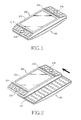
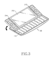
- the mobile terminal comprises a body housing 100, and a sliding and pivotable housing 200 designed to be matched with the body housing. More specifically, the sliding and pivotable housing 200 is designed to first be slid face-to-face on the body housing 100 (FIG. 2), and then to be pivoted to a slanting position on the body housing 100 (FIG. 3).
- the body housing 100 is provided with a plurality of first keys 110.
- the sliding and pivotable housing 200 has a plurality of second keys 216 and 218.
- the mobile terminal has at least one speaker device, as shown for example in FIGS. 1 - 3 illustrating an implementation using a plurality of speaker devices 212 and 214.
- FIG. 2 shows the sliding and pivotable housing 200 slid to a given distance
- FIG. 3 shows the sliding and pivotable housing 200 in a slanting position after the sliding movement.
- the sliding and pivotable housing 200 encases a display 210, first and second speaker devices 212 and 214 arranged at both sides of the display 210, and first and second keypads 216 and 218 arranged at the respective sides of the first and second speaker devices 212 and 214.
- the first and second speaker devices 212 and 214 intensify the acoustic effect at both sides of the display 210
- the first and second keypads 216 and 218 facilitate the user's operation of the keys while watching the display 210.
- the display 210 may be an LCD or a touch screen, and the screen is designed to protrude by a given thickness from the surface of the first and second keypads 216 and 218 to facilitate a user's concentration on the display. Accordingly, the first and second speaker devices 212 and 214 and the display 210 preferably directly face the user to enable the user to enjoy the visual and acoustic effects more effectively.
- the body housing 100 has the first keys 110 arranged in the QWERTY scheme on its surface, and a transverse groove 112 for accommodating the pivoting of the sliding and pivotable housing.
- the transverse groove 112 is formed along the direction substantially perpendicular to the sliding direction of the sliding and pivotable housing 200 and lengthwise of the body housing 100.
- the position of the mobile terminal as shown in FIG. 1 is suitable for the phone or MP3 mode, and that of FIG. 2 for the game or chatting mode, and that of FIG. 3 for the DMB mode.
- the position of the mobile terminal shown in FIG. 3 enables the user to enjoy the visual and acoustic effects more effectively because the display and speakers rested in a slanting position directly face the user.
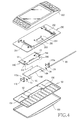
- the sliding cradle according to exemplary embodiments of the present invention provided in the mobile terminal comprises a first member 150 fastened to the body housing 100, a second member 250 fastened to the sliding and pivotable housing 200, a sliding guide part arranged between the first and second members 150 and 250, a fixture member 160 fastened to the first member, and a pivot control device connected with the first and second members to substantially prevent the sliding and pivotable housing 200 from pivoting during the sliding movement and to enable it to pivot upon completion of the sliding movement.
- the first and second members 150 and 250 have generally plate-like shapes and are respectively mounted on the top of the body housing 100 and on the bottom of the sliding and pivotable housing 200.
- the sliding guide part arranged between the first and second members 150 and 250 guides the sliding movement of the sliding and pivotable housing 200, and is provided with a pivot member 246 for pivoting the second member 250 and thus the sliding and pivotable housing 200 apart from the first member 150.
- the sliding movement of the sliding and pivotable housing 200 is performed while rested horizontally on the body housing 100 by the sliding guide part.
- the fixture member 160 is fastened to the first member 150 by means of fastening means (not shown) to face the sliding guide part, and is connected to the pivot member 246 to support a sliding and pivotable member 240.
- the sliding guide part comprises a sliding guide depression 260 (shown in FIG. 5) formed in the underside of the second member 250 with a guide rail 261 provided on both edges of the sliding guide depression the sliding and pivotable member 240 is inserted into the sliding guide depression 260, and the pivot member 246 is integrated with the sliding and pivotable member 240.
- a pivot mechanism is provided between the sliding and pivotable member 240 and the fixture member 160 and includes the pivot member 246 serving as a hinge device for the sliding and pivotable housing 200.
- the sliding guide depression 260 further includes tracking cuts 262 formed on the respective guide rails 261 for accommodating the tracking of first resilient members S 1 and S2.
- the pivot mechanism comprises a pair of first supports 151 and 153 (shown in FIG. 5) formed on the underside of the first member 150 to face each other, the pivot 180 mounted to cross the first supports 151 and 153, the pivot member 246 mounted on the pivot 180 for allowing the sliding and pivotable member 240 to pivot, and a pair of second supports 162 and 164 provided at the fixture member 160 for supporting the pivot 180.
- the sliding and pivotable member 240 may only be pivoted on the pivot 180, which is supported by the fixture member 160 fixedly mounted on the first member 150.
- the first resilient members S1 and S2 provided in the sliding guide part provide a resilient force to supply a closing or an opening force accordingly as the sliding and pivotable housing 200 is within or outside of a given distance. Namely, when the user initially exerts a given force to the sliding and pivotable housing 200, it keeps on sliding automatically by semi-automatic operation of the first resilient members S1 and S2.
- the first resilient members include a first and a second torsion spring S1 and S2 arranged between the sliding and pivotable member 240 and the second member 250.
- the first torsion spring S1 has two ends respectively fixed in a fixing hole 242 of the sliding and pivotable member 240 and a fixing hole 253 of the second member 250.
- the second torsion spring S2 has two ends respectively fixed in a fixing hole 244 of the sliding and pivotable member 240 and a fixing hole 254 of the second member 250.
- the sliding guide part further includes second resilient members S3 and S4 mounted on the pivot 180 for providing a resilient force to pivot the sliding and pivotable housing 200 by a given angle upon completion of the sliding movement.
- the second resilient members S3 and S4 are concentrically mounted on the pivot member 246 with their two ends respectively held by the first and second members 150 and 250.
- the second resilient members include third and fourth torsion springs S3 and S4 mounted concentrically on the pivot 180.
- the sliding cradle enables the sliding and pivotable housing 200 to be semi-automatically slid relative to the body housing without pivoting, and to pivot by a given angle to a fixed slanting position after completing the sliding movement.
- the sliding cradle includes a pivot control device, which comprises a pair of first and second retaining guide members 251 and 252 formed on the upper surface of the second member 250 with closed ends, a pair of first and second connecting members 170 and 172 each having two ends, first ends being mounted on the pivot 180 and second ends 170a and 172a being rested on the retaining guide members to slide along them according to the sliding movement of the second member, and an opening structure formed at the retaining guide members 251 and 252 to provide both sliding and pivoting space for the sliding and pivotable housing 200 in cooperation with the other ends of the connecting members.
- a pivot control device which comprises a pair of first and second retaining guide members 251 and 252 formed on the upper surface of the second member 250 with closed ends, a pair of first and second connecting members 170 and 172 each having two ends, first ends being mounted on the pivot 180 and second ends 170a and 172a being rested on the retaining guide members to slide along them according to the sliding movement of the second member, and an opening structure formed at the
- the first and second connecting members 170 and 172 are designed to penetrate respectively the first and second retaining guide members 251 and 252, and the second ends 170a and 172a of the connecting members have substantially cylindrical shapes extending along the axis of the pivot member 246.
- the first ends of the connecting members 170 and 172 are attached to the first member 150 through first and second slits 154 and 156 formed therein.
- the opening structure comprises a first opening 256 facing upwardly along the length of the retaining guide member 251 for allowing the sliding movement of the sliding and pivotable housing 200 in cooperation with the other end 172a of the connecting member 172, and a second opening 257 facing toward the bottom of the retaining guide member 251 for allowing the pivoting of the sliding and pivotable housing 200 after the sliding movement.
- the second opening 257 is designed to limit the pivoting of the sliding and pivotable housing 200 to a given angle.
- the first and second openings 256 and 257 communicate. Both ends 256a and 256b of the first opening 256 have curved shapes, and the second opening 257 has a substantially semi-cylindrical shape near the rear end of the retaining guide member 251.
- the other retaining guide member 252 and the other end 170a of the other connecting member 170 have substantially the same structure for cooperation. Additionally, the first and second members, sliding and pivotable member, and fixture member have respective openings 152, 255, 247, 168 for passing a flexible circuit therethrough.
- FIGS. 6A to 6C The operation of the mobile terminal is described in connection with FIGS. 6A to 6C.
- the sliding and pivotable housing 200 slides along the first opening 256 to the position shown in FIG. 6B.
- the other ends 170a and 172a of the connecting members enter the second openings 257 of the retaining guide members 251 and 252, so that the second resilient members S3 and S4 exert a resilient force to the second member 250 to pivot the sliding and pivotable housing 200 to the given slanting position as shown in FIG. 6C.
- the first opening 256 allows the sliding movement and the second opening 257 allows the pivoting movement.
- the amount of pivoting by the second member 250 is controlled by the shape of the second opening 257, such that modifying the shape of the second opening 257 changes the amount of pivoting possible by the second member 250. Namely, the pivoting amount of the sliding and pivotable housing 200 is increased with the depth of the second opening 257. Additionally, the sliding distance of the second member is adjusted by modifying the shape of the first opening 256.
- FIG. 7 shows the second member 250 pivoted to a given slanting position with the second end 170a inserted in the second opening 257.
- the sliding and pivotable housing 200 is described as automatically pivoted after having slid by a given distance (100% of the whole sliding interval), but it may be designed to pivot by an additional force externally exerted after completing the sliding movement. Or otherwise, it may be designed to automatically slide by a given distance (about 80% of the whole sliding interval) and then to be pivoted by exerting an additional force after completing the sliding movement of the remaining distance (about 20% of the whole sliding interval) by an additional force externally exerted. It may also be designed both to automatically slide and pivot.
- the operational force may be applied manually, semi-automatically by using a resilient member like a torsion spring, and fully automatically by using a motor.
- the invention enables the display and the speakers of the mobile terminal to be rested in a slanting position on a table, so that the user may enjoy the visual and acoustic effects more effectively. While the invention has been shown and described with reference to certain exemplary embodiments thereof, it will be understood by those skilled in the art that various changes in form and details may be made therein without departing from the spirit and principle of the invention, the scope of which is defined in the appended claims and their equivalents.
Landscapes
- Engineering & Computer Science (AREA)
- Physics & Mathematics (AREA)
- Theoretical Computer Science (AREA)
- Computer Hardware Design (AREA)
- Signal Processing (AREA)
- Mathematical Physics (AREA)
- Human Computer Interaction (AREA)
- General Engineering & Computer Science (AREA)
- General Physics & Mathematics (AREA)
- Computer Networks & Wireless Communication (AREA)
- Telephone Set Structure (AREA)
Applications Claiming Priority (1)
| Application Number | Priority Date | Filing Date | Title |
|---|---|---|---|
| KR1020050105948A KR101232951B1 (ko) | 2005-11-07 | 2005-11-07 | 시청이 편리한 휴대 단말기 및 그의 슬라이딩 거치 장치 |
Publications (2)
| Publication Number | Publication Date |
|---|---|
| EP1783984A1 true EP1783984A1 (de) | 2007-05-09 |
| EP1783984B1 EP1783984B1 (de) | 2012-02-22 |
Family
ID=37762396
Family Applications (1)
| Application Number | Title | Priority Date | Filing Date |
|---|---|---|---|
| EP06021553A Not-in-force EP1783984B1 (de) | 2005-11-07 | 2006-10-13 | Mobiles Endgerät mit Schiebevorrichtung und Schiebevorrichtung dazu |
Country Status (4)
| Country | Link |
|---|---|
| US (1) | US8086290B2 (de) |
| EP (1) | EP1783984B1 (de) |
| KR (1) | KR101232951B1 (de) |
| CN (1) | CN1964374B (de) |
Cited By (11)
| Publication number | Priority date | Publication date | Assignee | Title |
|---|---|---|---|---|
| WO2009080869A1 (en) * | 2007-12-20 | 2009-07-02 | Nokia Corporation | Slide mechanism |
| EP2180669A1 (de) * | 2008-10-22 | 2010-04-28 | Hanbit Precision Co., Ltd. | Schiebegelenkmodul für ein Mobiltelefon mit eingebauter Tastatur |
| EP2187599A1 (de) * | 2008-11-12 | 2010-05-19 | HTC Corporation | Verschiebbares und kippbares, tragbares elektronisches Gerät |
| CN101304647B (zh) * | 2007-05-10 | 2010-07-21 | 宏达国际电子股份有限公司 | 移动总成及应用该移动总成的可携式电子装置 |
| WO2010128989A1 (en) * | 2009-05-08 | 2010-11-11 | Sony Ericsson Mobile Communications Ab | Slideable hinge mobile communications device |
| GB2472576A (en) * | 2009-08-10 | 2011-02-16 | Unication Co Ltd | A keyboard combinable with an electronic device |
| WO2011073749A1 (en) * | 2009-12-18 | 2011-06-23 | Sony Ericsson Mobile Communications Ab | Keyboard and display screen in separate housings connected by cam assemblies that tilt responsive to movement between the housings |
| CN101304646B (zh) * | 2007-05-10 | 2011-11-30 | 宏达国际电子股份有限公司 | 具有可相对转动的机体的可携式电子装置 |
| EP2273768A3 (de) * | 2009-07-06 | 2013-07-03 | LG Electronics Inc. | Mobiles Endgerät mit kippbarem Gleitmodul |
| EP2593912A4 (de) * | 2010-07-14 | 2014-08-06 | Patrick Bouaziz | System, verfahren und vorrichtung zur erleichterung von kommerz und handel |
| EP2509287A4 (de) * | 2009-12-01 | 2014-11-05 | Mitsubishi Steel Mfg | Schiebe- und kippmechanismus |
Families Citing this family (92)
| Publication number | Priority date | Publication date | Assignee | Title |
|---|---|---|---|---|
| EP1794004A4 (de) * | 2004-08-13 | 2012-05-09 | Examples Inc 5 | Einreihige tastatur und approximierungstippen |
| KR100726468B1 (ko) * | 2005-06-27 | 2007-06-11 | (주)케이티에프테크놀로지스 | 힌지장치 및 이를 이용한 휴대용 단말기 |
| KR100678215B1 (ko) * | 2006-04-07 | 2007-02-02 | 삼성전자주식회사 | 휴대 단말기 및 그의 슬라이딩 거치 장치 |
| US7583989B2 (en) * | 2006-04-18 | 2009-09-01 | Cheng Uei Precision Industry Co., Ltd. | Sliding-type hinge |
| KR100833241B1 (ko) * | 2006-04-28 | 2008-05-28 | 삼성전자주식회사 | 슬라이딩-틸트장치 및 이를 채용한 모바일 기기 |
| TWD120616S1 (zh) * | 2006-05-12 | 2007-12-21 | 新力股份有限公司 | 電腦 |
| USD558720S1 (en) * | 2006-05-18 | 2008-01-01 | Samsung Electronics Co., Ltd. | Portable phone |
| US20080052874A1 (en) * | 2006-08-16 | 2008-03-06 | Shin Zu Shing Co., Ltd. | Flat hinge assembly |
| US7831286B2 (en) * | 2006-12-26 | 2010-11-09 | Samsung Techwin Co., Ltd. | Sliding structure for electronic device |
| TWI327264B (en) * | 2007-01-19 | 2010-07-11 | Asustek Comp Inc | Handheld electronic device |
| USD590825S1 (en) * | 2007-05-31 | 2009-04-21 | Compal Electronics, Inc. | Mobile personal computer |
| TWI329252B (en) * | 2007-06-01 | 2010-08-21 | Asustek Comp Inc | Portable electronic device |
| TW200848983A (en) * | 2007-06-05 | 2008-12-16 | Asustek Comp Inc | Portable electronic device |
| TWI413037B (zh) * | 2007-06-15 | 2013-10-21 | Creator Technology Bv | 具有可改變角度的可撓性顯示器的電子裝置 |
| US8131329B2 (en) * | 2007-07-06 | 2012-03-06 | Sony Ericsson Mobile Communications Ab | Distributed mode speaker for mobile devices |
| CN101355870B (zh) * | 2007-07-25 | 2012-03-14 | 深圳富泰宏精密工业有限公司 | 治具 |
| US8126519B2 (en) * | 2007-08-31 | 2012-02-28 | Hewlett-Packard Development Company, L.P. | Housing for mobile computing device having construction to slide and pivot into multiple positions |
| CN101384151B (zh) * | 2007-09-03 | 2011-02-02 | 华硕电脑股份有限公司 | 翻盖机构及其应用的电子装置 |
| TWI358935B (en) * | 2007-09-20 | 2012-02-21 | Asustek Comp Inc | Electronic device and sliding cover structure |
| TW200917929A (en) * | 2007-10-05 | 2009-04-16 | Qisda Corp | Bilateral sliding module and the electronic device for using the same |
| CN101822028B (zh) * | 2007-10-11 | 2014-06-25 | 日本电气株式会社 | 便携式信息处理终端 |
| TWI337518B (en) * | 2007-11-07 | 2011-02-11 | Htc Corp | Electronic device |
| CN101437369B (zh) * | 2007-11-14 | 2010-09-15 | 宏达国际电子股份有限公司 | 电子装置 |
| US20090170574A1 (en) * | 2007-12-28 | 2009-07-02 | Motorola Inc | Methods and slider form factor devices with contiguous surfaces when open |
| KR101529913B1 (ko) * | 2008-03-25 | 2015-06-18 | 엘지전자 주식회사 | 슬라이드 모듈 및 이를 구비하는 휴대 단말기 |
| US7933123B2 (en) * | 2008-04-11 | 2011-04-26 | Apple Inc. | Portable electronic device with two-piece housing |
| TWI366431B (en) * | 2008-05-05 | 2012-06-11 | Asustek Comp Inc | Torsion spring assembly and portable electronic device with torsion spring assembly |
| KR101039639B1 (ko) * | 2008-06-27 | 2011-06-09 | 삼성전자주식회사 | 휴대 단말기 및 그의 스피커 장치 |
| TWI454967B (zh) * | 2008-07-16 | 2014-10-01 | Htc Corp | 電子裝置及其鍵盤模組 |
| KR100977158B1 (ko) * | 2008-07-17 | 2010-08-23 | 주식회사 다이아벨 | 슬라이드 힌지 장치 |
| KR100971761B1 (ko) * | 2008-07-18 | 2010-07-21 | 에이치케이에스테크 주식회사 | 휴대단말기용 틸트힌지 및 이를 이용한 휴대단말기용 힌지모듈 |
| CN201260280Y (zh) * | 2008-08-01 | 2009-06-17 | 鸿富锦精密工业(深圳)有限公司 | 滑动翻盖式电子装置 |
| KR101495173B1 (ko) * | 2008-08-06 | 2015-03-02 | 엘지전자 주식회사 | 슬라이드 모듈 및 이를 구비하는 휴대 단말기 |
| TWI382733B (zh) * | 2008-08-25 | 2013-01-11 | Htc Corp | 滑蓋式電子裝置 |
| US8781540B2 (en) * | 2008-08-25 | 2014-07-15 | Htc Corporation | Portable electronic device |
| CN201278621Y (zh) * | 2008-08-29 | 2009-07-22 | 鸿富锦精密工业(深圳)有限公司 | 滑动翻盖式电子装置 |
| US8385992B2 (en) * | 2008-12-19 | 2013-02-26 | Nokia Corporation | User interfaces and associated apparatus and methods |
| CN201297335Y (zh) * | 2008-09-09 | 2009-08-26 | 鸿富锦精密工业(深圳)有限公司 | 枢纽器 |
| KR101007846B1 (ko) * | 2008-11-12 | 2011-01-13 | 삼광티엘티(주) | 힌지 모듈 및 이를 이용한 이동통신 단말기 |
| KR100996404B1 (ko) * | 2008-11-14 | 2010-11-24 | (주)쉘라인 | 틸팅 가능한 슬라이드형 개인휴대단말기 |
| US20100124953A1 (en) * | 2008-11-18 | 2010-05-20 | Yi-Che Yang | Electronic device with a sliding and rotating cover |
| KR101517238B1 (ko) * | 2008-11-20 | 2015-05-04 | 삼성전자주식회사 | 휴대용 전자 기기의 거치 장치 |
| TWI372826B (en) * | 2008-12-12 | 2012-09-21 | Htc Corp | Moving assembly, handheld electronic device and operating method thereof |
| WO2010085057A2 (ko) * | 2009-01-22 | 2010-07-29 | 주식회사 세이텍 | 슬라이딩 모듈 및 이에 사용되는 구동장치 |
| TWI363143B (en) * | 2009-06-18 | 2012-05-01 | Htc Corp | Electronic device and moving mechanism thereof |
| KR101659002B1 (ko) * | 2009-08-27 | 2016-09-23 | 엘지전자 주식회사 | 이동 단말기 |
| KR101633102B1 (ko) * | 2009-08-05 | 2016-06-24 | 삼성전자주식회사 | 휴대용 통신 장치의 거치 장치 |
| USD626109S1 (en) * | 2009-09-30 | 2010-10-26 | Samsung Electronics Co., Ltd. | Mobile phone |
| KR101054368B1 (ko) * | 2009-11-06 | 2011-08-04 | 암페놀피닉스 유한회사 | 힌지 유닛 및 이를 갖는 휴대용 전자기기의 개폐장치 |
| TWI401560B (zh) * | 2009-11-24 | 2013-07-11 | Htc Corp | 電子裝置 |
| KR101129266B1 (ko) * | 2009-11-26 | 2012-03-26 | 주식회사 다이아벨 | 슬라이딩 장치 및 이를 구비하는 전자기기 |
| CN201590010U (zh) * | 2009-11-30 | 2010-09-22 | 康准电子科技(昆山)有限公司 | 翻盖装置 |
| KR101142554B1 (ko) * | 2009-11-30 | 2012-05-08 | 주식회사 팬택 | 단말기 및 이의 슬라이딩장치 |
| TWI369605B (en) * | 2009-12-08 | 2012-08-01 | Htc Corp | Handheld electronic device |
| US8483784B2 (en) * | 2009-12-18 | 2013-07-09 | Research In Motion Limited | Mobile communications device having a rotatable member |
| CN102105027A (zh) * | 2009-12-22 | 2011-06-22 | 鸿富锦精密工业(深圳)有限公司 | 便携式电子装置 |
| CN102118936B (zh) * | 2009-12-30 | 2014-10-29 | 深圳富泰宏精密工业有限公司 | 滑动型电子装置 |
| CN102118944A (zh) * | 2009-12-31 | 2011-07-06 | 深圳富泰宏精密工业有限公司 | 滑动型电子装置 |
| CN102118940A (zh) * | 2009-12-31 | 2011-07-06 | 深圳富泰宏精密工业有限公司 | 滑动型电子装置 |
| CN102118945A (zh) * | 2010-01-06 | 2011-07-06 | 深圳富泰宏精密工业有限公司 | 滑盖结构及应用该滑盖结构的便携式电子装置 |
| US20110164352A1 (en) * | 2010-01-07 | 2011-07-07 | Sony Ericsson Mobile Communications Ab | Double sliding mechanism for user devices |
| CN102131363B (zh) * | 2010-01-15 | 2014-10-29 | 深圳富泰宏精密工业有限公司 | 电子装置 |
| CN102131364A (zh) * | 2010-01-15 | 2011-07-20 | 深圳富泰宏精密工业有限公司 | 便携式电子装置 |
| US8843183B2 (en) * | 2010-01-15 | 2014-09-23 | Blackberry Limited | Mobile communication device having overlapping first and second body members |
| CN102131362B (zh) * | 2010-01-15 | 2014-10-29 | 深圳富泰宏精密工业有限公司 | 便携式电子装置 |
| US8363391B2 (en) * | 2010-01-26 | 2013-01-29 | Samsung Electronics Co., Ltd. | Portable terminal |
| KR101101073B1 (ko) * | 2010-02-11 | 2011-12-30 | 주식회사 팬택 | 단말기 |
| US8284554B2 (en) * | 2010-02-15 | 2012-10-09 | Motorola Mobility Llc | Electronic device housing with pivoting and sliding portions |
| KR101107122B1 (ko) * | 2010-02-23 | 2012-01-31 | 주식회사 다이아벨 | 모바일 기기 |
| CN102215643A (zh) * | 2010-04-02 | 2011-10-12 | 深圳富泰宏精密工业有限公司 | 便携式电子装置 |
| EP2387208B1 (de) * | 2010-05-10 | 2014-03-05 | BlackBerry Limited | Tragbare elektronische Kommunikationsvorrichtung |
| US20130033161A1 (en) * | 2010-05-20 | 2013-02-07 | Nec Corporation | Sliding mechanism and portable device |
| WO2011145260A1 (ja) * | 2010-05-20 | 2011-11-24 | 日本電気株式会社 | 携帯機器 |
| KR101629262B1 (ko) * | 2010-05-31 | 2016-06-10 | 엘지전자 주식회사 | 이동 단말기 |
| TWI510047B (zh) * | 2010-07-20 | 2015-11-21 | Htc Corp | 手持電子裝置 |
| CN201781710U (zh) * | 2010-07-30 | 2011-03-30 | 国基电子(上海)有限公司 | 便携式电子装置 |
| KR101107125B1 (ko) * | 2010-08-24 | 2012-01-31 | 주식회사 다이아벨 | 슬라이딩 장치 및 이를 구비하는 전자기기 |
| KR101728387B1 (ko) * | 2010-09-27 | 2017-04-19 | 엘지전자 주식회사 | 휴대 단말기 |
| KR101695989B1 (ko) * | 2010-11-01 | 2017-01-13 | 삼성전자주식회사 | 휴대용 단말기 |
| CN102548295B (zh) * | 2010-12-22 | 2015-04-08 | 温州泓呈祥科技有限公司 | 滑动模组及具有该滑动模组的电子装置 |
| JP5673096B2 (ja) * | 2010-12-28 | 2015-02-18 | ソニー株式会社 | 機器開閉機構および情報機器 |
| CN102573354B (zh) * | 2010-12-31 | 2015-04-15 | 淮南东正电子科技有限公司 | 滑动模组及具有该滑动模组的电子装置 |
| TWI415553B (zh) * | 2011-01-06 | 2013-11-11 | Htc Corp | 手持式電子裝置 |
| US8911165B2 (en) | 2011-01-24 | 2014-12-16 | 5 Examples, Inc. | Overloaded typing apparatuses, and related devices, systems, and methods |
| USD701862S1 (en) * | 2011-02-18 | 2014-04-01 | Lg Electronics Inc. | Cart barcode scanner |
| US8769772B2 (en) | 2011-08-10 | 2014-07-08 | Blackberry Limited | Mobile electronic device having member rotatable between first and second positions |
| WO2013103165A1 (ko) * | 2012-01-05 | 2013-07-11 | (주)쉘라인 | 틸팅 가능한 개인휴대단말기 |
| USD739391S1 (en) | 2013-01-16 | 2015-09-22 | Htc Corporation | Portable electronic device |
| CN104181844B (zh) * | 2014-08-20 | 2016-09-28 | 江苏省电力公司 | 互动式平台终端 |
| CN110133992B (zh) * | 2018-09-29 | 2023-09-22 | 广东小天才科技有限公司 | 拍摄方向可调的智能手表 |
| CN110133985B (zh) * | 2018-09-29 | 2024-08-23 | 广东小天才科技有限公司 | 智能主机及具有该智能主机的智能穿戴设备 |
| WO2024167255A1 (ko) * | 2023-02-10 | 2024-08-15 | 주식회사 에크리어 | 포터블 모니터 |
Citations (5)
| Publication number | Priority date | Publication date | Assignee | Title |
|---|---|---|---|---|
| EP1312999A2 (de) * | 2001-11-09 | 2003-05-21 | Nokia Corporation | Multifunktion Mobilkommunikationsgerät mit verschiebbarem Bildschirm |
| EP1422911A2 (de) * | 2002-11-19 | 2004-05-26 | Samsung Electronics Co., Ltd. | Verschiebbares und tragbares Mobiltelefon |
| EP1439685A1 (de) * | 2003-01-17 | 2004-07-21 | Motorola, Inc. | Gehäuse für ein klappbares Telefon |
| US20050044665A1 (en) * | 2003-08-18 | 2005-03-03 | Ryuta Kuramochi | Slide hinge for small-sized information terminal |
| TWM263698U (en) * | 2004-10-04 | 2005-05-01 | Hith Tech Comp Corp | Portable electronic apparatus with dual operations |
Family Cites Families (5)
| Publication number | Priority date | Publication date | Assignee | Title |
|---|---|---|---|---|
| WO2003021408A2 (en) * | 2001-08-29 | 2003-03-13 | Danger, Inc. | Sliding display apparatus |
| KR20040104878A (ko) | 2003-06-04 | 2004-12-13 | 김성균 | 슬라이드형 휴대용 전화기. |
| KR100533038B1 (ko) * | 2003-12-30 | 2005-12-02 | 엘지전자 주식회사 | 휴대용 단말기의 개폐장치 |
| KR101029809B1 (ko) | 2004-02-04 | 2011-04-20 | 엘지전자 주식회사 | 슬라이드형 이동통신 단말기 |
| KR20050079161A (ko) * | 2004-02-04 | 2005-08-09 | 주식회사 팬택앤큐리텔 | 개방각도 조절기능이 구비된 슬라이딩식 이동통신 단말기 |
-
2005
- 2005-11-07 KR KR1020050105948A patent/KR101232951B1/ko not_active Expired - Fee Related
-
2006
- 2006-09-07 US US11/516,554 patent/US8086290B2/en not_active Expired - Fee Related
- 2006-10-12 CN CN2006101318089A patent/CN1964374B/zh not_active Expired - Fee Related
- 2006-10-13 EP EP06021553A patent/EP1783984B1/de not_active Not-in-force
Patent Citations (5)
| Publication number | Priority date | Publication date | Assignee | Title |
|---|---|---|---|---|
| EP1312999A2 (de) * | 2001-11-09 | 2003-05-21 | Nokia Corporation | Multifunktion Mobilkommunikationsgerät mit verschiebbarem Bildschirm |
| EP1422911A2 (de) * | 2002-11-19 | 2004-05-26 | Samsung Electronics Co., Ltd. | Verschiebbares und tragbares Mobiltelefon |
| EP1439685A1 (de) * | 2003-01-17 | 2004-07-21 | Motorola, Inc. | Gehäuse für ein klappbares Telefon |
| US20050044665A1 (en) * | 2003-08-18 | 2005-03-03 | Ryuta Kuramochi | Slide hinge for small-sized information terminal |
| TWM263698U (en) * | 2004-10-04 | 2005-05-01 | Hith Tech Comp Corp | Portable electronic apparatus with dual operations |
Cited By (15)
| Publication number | Priority date | Publication date | Assignee | Title |
|---|---|---|---|---|
| CN101304647B (zh) * | 2007-05-10 | 2010-07-21 | 宏达国际电子股份有限公司 | 移动总成及应用该移动总成的可携式电子装置 |
| CN101304646B (zh) * | 2007-05-10 | 2011-11-30 | 宏达国际电子股份有限公司 | 具有可相对转动的机体的可携式电子装置 |
| US8121659B2 (en) | 2007-12-20 | 2012-02-21 | Nokia Corporation | Slide mechanism |
| WO2009080869A1 (en) * | 2007-12-20 | 2009-07-02 | Nokia Corporation | Slide mechanism |
| EP2180669A1 (de) * | 2008-10-22 | 2010-04-28 | Hanbit Precision Co., Ltd. | Schiebegelenkmodul für ein Mobiltelefon mit eingebauter Tastatur |
| EP2187599A1 (de) * | 2008-11-12 | 2010-05-19 | HTC Corporation | Verschiebbares und kippbares, tragbares elektronisches Gerät |
| US7872861B2 (en) | 2008-11-12 | 2011-01-18 | Htc Corporation | Portable electronic device |
| WO2010128989A1 (en) * | 2009-05-08 | 2010-11-11 | Sony Ericsson Mobile Communications Ab | Slideable hinge mobile communications device |
| EP2273768A3 (de) * | 2009-07-06 | 2013-07-03 | LG Electronics Inc. | Mobiles Endgerät mit kippbarem Gleitmodul |
| GB2472576A (en) * | 2009-08-10 | 2011-02-16 | Unication Co Ltd | A keyboard combinable with an electronic device |
| GB2472576B (en) * | 2009-08-10 | 2012-01-04 | Unication Co Ltd | Structure of keyboard combinable with electronic device |
| EP2509287A4 (de) * | 2009-12-01 | 2014-11-05 | Mitsubishi Steel Mfg | Schiebe- und kippmechanismus |
| US8149581B2 (en) | 2009-12-18 | 2012-04-03 | Sony Ericssom Mobile Communications AB | Keyboard and display screen in separate housings connected by cam assemblies that tilt responsive to movement between the housings |
| WO2011073749A1 (en) * | 2009-12-18 | 2011-06-23 | Sony Ericsson Mobile Communications Ab | Keyboard and display screen in separate housings connected by cam assemblies that tilt responsive to movement between the housings |
| EP2593912A4 (de) * | 2010-07-14 | 2014-08-06 | Patrick Bouaziz | System, verfahren und vorrichtung zur erleichterung von kommerz und handel |
Also Published As
| Publication number | Publication date |
|---|---|
| US8086290B2 (en) | 2011-12-27 |
| CN1964374B (zh) | 2011-07-20 |
| CN1964374A (zh) | 2007-05-16 |
| US20070105606A1 (en) | 2007-05-10 |
| KR101232951B1 (ko) | 2013-02-13 |
| KR20070048895A (ko) | 2007-05-10 |
| EP1783984B1 (de) | 2012-02-22 |
Similar Documents
| Publication | Publication Date | Title |
|---|---|---|
| EP1783984B1 (de) | Mobiles Endgerät mit Schiebevorrichtung und Schiebevorrichtung dazu | |
| US8380257B2 (en) | Swing-type mobile communication terminal and swing device thereof | |
| EP1775596B1 (de) | Tastatur für ein verschiebbares Mobilgerät | |
| EP1898605B1 (de) | Tasteneingabevorrichtung für ein tragbares Kommunikationsgerät und Schiebemodul dafür | |
| US7853301B2 (en) | Sliding module for double sliding-type portable communication terminal | |
| EP1928158A1 (de) | Multimedia-Mobiltelefon mit Selbstschwenkfunktion | |
| US20080051162A1 (en) | Mobile phone having dual connection member and hinge device thereof | |
| EP1901532A2 (de) | Aufklappbares Mobiltelefon | |
| US20070184882A1 (en) | Portable communication terminal for games | |
| US7945299B2 (en) | Multiple torsion spring and semi-automatic sliding device using the same | |
| KR20070042346A (ko) | 시청이 편리한 휴대 단말기 및 그의 슬라이딩 거치 장치 | |
| US8380261B2 (en) | Sliding-type mobile terminal with a sliding cradle, sliding guide module thereof and mechanism for mounting sliding guide module | |
| US20050124395A1 (en) | Portable communication apparatus and method thereof | |
| CN101141500B (zh) | 滑动式便携终端 | |
| WO2008082080A1 (en) | A portable terminal of slide-down opening and closing type | |
| KR20070071462A (ko) | 슬라이드형 이동통신 단말기 | |
| KR100849298B1 (ko) | 휴대 단말기의 슬라이딩 모듈 | |
| KR100790106B1 (ko) | 거치대를 구비하는 휴대용 단말기 | |
| KR20060031097A (ko) | 슬라이드형 이동 통신 단말기 | |
| KR100639506B1 (ko) | 회전 가능한 액정화면이 구비된 이동통신 단말기 | |
| KR20070078192A (ko) | 슬라이드형 이동통신 단말기 | |
| KR100889098B1 (ko) | 슬라이드부의 각도 조절 구조를 가지는 휴대용 단말기 | |
| KR200389382Y1 (ko) | 슬라이드형 이동통신 단말기 | |
| KR100651538B1 (ko) | 휴대용 단말기 | |
| KR101297013B1 (ko) | 곡형 슬라이딩 타입 휴대 단말기의 반 자동 슬라이딩 장치 |
Legal Events
| Date | Code | Title | Description |
|---|---|---|---|
| PUAI | Public reference made under article 153(3) epc to a published international application that has entered the european phase |
Free format text: ORIGINAL CODE: 0009012 |
|
| 17P | Request for examination filed |
Effective date: 20061013 |
|
| AK | Designated contracting states |
Kind code of ref document: A1 Designated state(s): AT BE BG CH CY CZ DE DK EE ES FI FR GB GR HU IE IS IT LI LT LU LV MC NL PL PT RO SE SI SK TR |
|
| AX | Request for extension of the european patent |
Extension state: AL BA HR MK YU |
|
| 17Q | First examination report despatched |
Effective date: 20071115 |
|
| AKX | Designation fees paid |
Designated state(s): DE FR GB |
|
| GRAP | Despatch of communication of intention to grant a patent |
Free format text: ORIGINAL CODE: EPIDOSNIGR1 |
|
| GRAS | Grant fee paid |
Free format text: ORIGINAL CODE: EPIDOSNIGR3 |
|
| GRAA | (expected) grant |
Free format text: ORIGINAL CODE: 0009210 |
|
| AK | Designated contracting states |
Kind code of ref document: B1 Designated state(s): DE FR GB |
|
| REG | Reference to a national code |
Ref country code: GB Ref legal event code: FG4D |
|
| REG | Reference to a national code |
Ref country code: DE Ref legal event code: R096 Ref document number: 602006027719 Country of ref document: DE Effective date: 20120419 |
|
| RAP2 | Party data changed (patent owner data changed or rights of a patent transferred) |
Owner name: SAMSUNG ELECTRONICS CO., LTD. |
|
| PLBE | No opposition filed within time limit |
Free format text: ORIGINAL CODE: 0009261 |
|
| STAA | Information on the status of an ep patent application or granted ep patent |
Free format text: STATUS: NO OPPOSITION FILED WITHIN TIME LIMIT |
|
| 26N | No opposition filed |
Effective date: 20121123 |
|
| REG | Reference to a national code |
Ref country code: DE Ref legal event code: R097 Ref document number: 602006027719 Country of ref document: DE Effective date: 20121123 |
|
| REG | Reference to a national code |
Ref country code: FR Ref legal event code: PLFP Year of fee payment: 11 |
|
| REG | Reference to a national code |
Ref country code: FR Ref legal event code: PLFP Year of fee payment: 12 |
|
| REG | Reference to a national code |
Ref country code: FR Ref legal event code: PLFP Year of fee payment: 13 |
|
| PGFP | Annual fee paid to national office [announced via postgrant information from national office to epo] |
Ref country code: FR Payment date: 20190923 Year of fee payment: 14 |
|
| PGFP | Annual fee paid to national office [announced via postgrant information from national office to epo] |
Ref country code: GB Payment date: 20190923 Year of fee payment: 14 |
|
| PGFP | Annual fee paid to national office [announced via postgrant information from national office to epo] |
Ref country code: DE Payment date: 20190920 Year of fee payment: 14 |
|
| REG | Reference to a national code |
Ref country code: DE Ref legal event code: R119 Ref document number: 602006027719 Country of ref document: DE |
|
| GBPC | Gb: european patent ceased through non-payment of renewal fee |
Effective date: 20201013 |
|
| PG25 | Lapsed in a contracting state [announced via postgrant information from national office to epo] |
Ref country code: DE Free format text: LAPSE BECAUSE OF NON-PAYMENT OF DUE FEES Effective date: 20210501 Ref country code: FR Free format text: LAPSE BECAUSE OF NON-PAYMENT OF DUE FEES Effective date: 20201031 |
|
| PG25 | Lapsed in a contracting state [announced via postgrant information from national office to epo] |
Ref country code: GB Free format text: LAPSE BECAUSE OF NON-PAYMENT OF DUE FEES Effective date: 20201013 |