EP1784058A2 - Segmentierte berührungsempfindliche Bildschirmkonsole mit Andoken von Module - Google Patents
Segmentierte berührungsempfindliche Bildschirmkonsole mit Andoken von Module Download PDFInfo
- Publication number
- EP1784058A2 EP1784058A2 EP06122624A EP06122624A EP1784058A2 EP 1784058 A2 EP1784058 A2 EP 1784058A2 EP 06122624 A EP06122624 A EP 06122624A EP 06122624 A EP06122624 A EP 06122624A EP 1784058 A2 EP1784058 A2 EP 1784058A2
- Authority
- EP
- European Patent Office
- Prior art keywords
- touch screen
- module
- display
- console
- segments
- Prior art date
- Legal status (The legal status is an assumption and is not a legal conclusion. Google has not performed a legal analysis and makes no representation as to the accuracy of the status listed.)
- Granted
Links
Images




Classifications
-
- G—PHYSICS
- G06—COMPUTING OR CALCULATING; COUNTING
- G06F—ELECTRIC DIGITAL DATA PROCESSING
- G06F3/00—Input arrangements for transferring data to be processed into a form capable of being handled by the computer; Output arrangements for transferring data from processing unit to output unit, e.g. interface arrangements
- G06F3/01—Input arrangements or combined input and output arrangements for interaction between user and computer
- G06F3/02—Input arrangements using manually operated switches, e.g. using keyboards or dials
- G06F3/0202—Constructional details or processes of manufacture of the input device
- G06F3/0219—Special purpose keyboards
-
- G—PHYSICS
- G06—COMPUTING OR CALCULATING; COUNTING
- G06F—ELECTRIC DIGITAL DATA PROCESSING
- G06F3/00—Input arrangements for transferring data to be processed into a form capable of being handled by the computer; Output arrangements for transferring data from processing unit to output unit, e.g. interface arrangements
- G06F3/01—Input arrangements or combined input and output arrangements for interaction between user and computer
- G06F3/03—Arrangements for converting the position or the displacement of a member into a coded form
- G06F3/041—Digitisers, e.g. for touch screens or touch pads, characterised by the transducing means
- G06F3/0416—Control or interface arrangements specially adapted for digitisers
- G06F3/04166—Details of scanning methods, e.g. sampling time, grouping of sub areas or time sharing with display driving
-
- G—PHYSICS
- G06—COMPUTING OR CALCULATING; COUNTING
- G06F—ELECTRIC DIGITAL DATA PROCESSING
- G06F3/00—Input arrangements for transferring data to be processed into a form capable of being handled by the computer; Output arrangements for transferring data from processing unit to output unit, e.g. interface arrangements
- G06F3/01—Input arrangements or combined input and output arrangements for interaction between user and computer
- G06F3/03—Arrangements for converting the position or the displacement of a member into a coded form
- G06F3/041—Digitisers, e.g. for touch screens or touch pads, characterised by the transducing means
- G06F3/045—Digitisers, e.g. for touch screens or touch pads, characterised by the transducing means using resistive elements, e.g. a single continuous surface or two parallel surfaces put in contact
-
- G—PHYSICS
- G06—COMPUTING OR CALCULATING; COUNTING
- G06F—ELECTRIC DIGITAL DATA PROCESSING
- G06F3/00—Input arrangements for transferring data to be processed into a form capable of being handled by the computer; Output arrangements for transferring data from processing unit to output unit, e.g. interface arrangements
- G06F3/01—Input arrangements or combined input and output arrangements for interaction between user and computer
- G06F3/048—Interaction techniques based on graphical user interfaces [GUI]
- G06F3/0487—Interaction techniques based on graphical user interfaces [GUI] using specific features provided by the input device, e.g. functions controlled by the rotation of a mouse with dual sensing arrangements, or of the nature of the input device, e.g. tap gestures based on pressure sensed by a digitiser
- G06F3/0488—Interaction techniques based on graphical user interfaces [GUI] using specific features provided by the input device, e.g. functions controlled by the rotation of a mouse with dual sensing arrangements, or of the nature of the input device, e.g. tap gestures based on pressure sensed by a digitiser using a touch-screen or digitiser, e.g. input of commands through traced gestures
-
- G—PHYSICS
- G06—COMPUTING OR CALCULATING; COUNTING
- G06F—ELECTRIC DIGITAL DATA PROCESSING
- G06F3/00—Input arrangements for transferring data to be processed into a form capable of being handled by the computer; Output arrangements for transferring data from processing unit to output unit, e.g. interface arrangements
- G06F3/01—Input arrangements or combined input and output arrangements for interaction between user and computer
- G06F3/048—Interaction techniques based on graphical user interfaces [GUI]
- G06F3/0487—Interaction techniques based on graphical user interfaces [GUI] using specific features provided by the input device, e.g. functions controlled by the rotation of a mouse with dual sensing arrangements, or of the nature of the input device, e.g. tap gestures based on pressure sensed by a digitiser
- G06F3/0489—Interaction techniques based on graphical user interfaces [GUI] using specific features provided by the input device, e.g. functions controlled by the rotation of a mouse with dual sensing arrangements, or of the nature of the input device, e.g. tap gestures based on pressure sensed by a digitiser using dedicated keyboard keys or combinations thereof
- G06F3/04895—Guidance during keyboard input operation, e.g. prompting
-
- G—PHYSICS
- G06—COMPUTING OR CALCULATING; COUNTING
- G06F—ELECTRIC DIGITAL DATA PROCESSING
- G06F2203/00—Indexing scheme relating to G06F3/00 - G06F3/048
- G06F2203/041—Indexing scheme relating to G06F3/041 - G06F3/045
- G06F2203/04106—Multi-sensing digitiser, i.e. digitiser using at least two different sensing technologies simultaneously or alternatively, e.g. for detecting pen and finger, for saving power or for improving position detection
Definitions
- the present invention relates to improvements in control consoles.
- Known control consoles include general purpose consoles such as personal computers with keyboards, processors, memory and displays, and also include special purpose consoles such as lighting control consoles, process control consoles and others.
- a conventional console may include user input devices such as keyboards, pointing devices, rotary and linear encoders and others.
- a conventional console may include one or more displays such as CRT or LCD or plasma displays.
- a conventional console may include a user input touch screen over one or each different display.
- Known consoles also typically include an operating system with a processor and memory, along with stand alone or integrated controllers for the display and touch screen
- consoles As the systems controlled by consoles become more complex, the consoles also become more complex, with a requirement for a large number of user inputs such as keyboard keys, encoders of various types and the need to display a large quantity of information.
- the physical size of dedicated, special purpose consoles such as lighting control consoles is increasing to provide of all the desired functionality. Complexity and large size are disadvantageous in control consoles. It would be desirable to increase the flexibility and customization potential of control consoles, and to optionally provide tactile feel for user input that is not possible with touch screen input.
- a primary object of the present invention is to provide improvements in control consoles.
- Other objects are to provide a console having segmented display and touch screen capability; to provide a console touch screen capable of producing touch position information at more than one location simultaneously; to provide a console touch screen with segments that can be individually disabled; to provide an improved console that can optionally accept docking user input modules at selected locations; to provide an improved console with automatic docking module detection; to provide a console with display and touch screen segments that can be controlled when a docking module is docked at a docking port to tailor a portion of the display for the module and to disable a touch screen segment under the module; and to provide an improved control console overcoming disadvantages of consoles known in the past.
- a control console including a display and a plurality of module docking ports adjacent the display.
- a plurality of touch screen segments are on the display.
- a docking module is receivable at any one of the module docking ports.
- a module detector is located at each docking ports.
- a touch screen controller disables one of the touch screen segments in response to a module detection signal from any of the module detectors.
- a console including an operating system, display controller and display for displaying information.
- a touch screen assembly overlies the display.
- the touch screen assembly includes a plurality of touch screen segments.
- a touch screen controller is continuously connected to each of the segments. The touch screen controller independently receives touch position information from each of the touch screen segments.
- FIG. 1 is an isometric view of a console constructed in accordance with the present invention
- FIG. 2 is a view like FIG. 1 with a docking module in place;
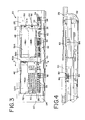
- FIG. 3 is an enlarged front view of the console and module of FIG. 2;
- FIG. 4 is a fragmentary, enlarged, cross sectional view taken along the line 4-4 of FIG. 3;
- FIG. 5 is an exploded isometric view of one of the touch screen assemblies of the console
- FIG. 6 is a top plan view of the top electrical layer of one of the touch screen assemblies, with the touch screen controller and touch screen electrical connections show schematically;
- FIG. 7 is an enlarged isometric view of a docking module for the console
- FIG. 8 is an exploded isometric view of the module of FIG. 7;
- FIG. 9 is an enlarged cross sectional view of the module taken along the line 9-9 of FIG. 7;
- FIG. 10 is a simplified schematic block diagram of some components of the console and module
- FIG. 11 is a flow chart of a routine for disabling any touch screen segment that is beneath a module
- FIG. 12 is an enlarged plan view of a display of the console 20 with no module in place on the display;
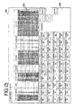
- FIG. 13 is a view like FIG. 12 of the display with one module in place on the display;
- FIG. 14 is a view like FIG. 12 of the display with two modules in place on the display;
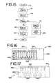
- FIG. 15 is a flow chart of a routine for providing touch screen position information.
- FIGS. 16 and 17 are top plan views of other types of docking modules for the console.
- the console 20 has a housing 22 including a base 24, a keyboard panel portion 26 and a display panel portion 28.
- the console 20 may be a lighting control console, but the principles of the invention are not limited to this application.
- the keyboard panel 26 supports a number of devices that can be employed by a user for manual input of commands including data and the like.
- a user inputs commands using buttons 30 of a keyboard 32 on the keyboard panel 26.
- Commands may also be input using a bank of rotary input devices or encoder wheels 34.
- a small display screen 36 displays legends for the wheels 34, and buttons 38 accept commands to control the display 36 and functions of wheels 34.
- Commands may also be entered with an additional pair of encoder wheels 40.
- Commands may also be entered using a bank of linear input devices or submaster faders 42 having functions controlled by buttons 44.
- the display panel 26 supports a pair of displays 46 and 48. These may be similar to one another, and each may be a fifteen inch diagonal flat panel liquid crystal display (LCD), although the principles of the invention are applicable to displays of other sizes and types.
- Displays 46 and 48 are functionally divided into upper segments 46A and 48A and lower segments 46B and 48B, separated by a line of potential division or separation that is not visible on the displays 46 and 48 but is indicated in the drawings by broken line 50.
- Some or all of the display segments 46A, 46B, 48A and 48B may be operated as a single unitary display group so that a continuous display is seen on the group. Thus segments 46A and 46B for example can display a single continuous graphic display. Each of the display segments 46A, 46B, 48A and 48B may also be operated separately on a functionally stand alone basis so that a separate, independent graphic display is seen on any one selected display segment.
- touch screen assemblies 52 and 54 In addition to entering commands using the devices associated with the keyboard panel 26, the user may also enter commands with touch screen assemblies 52 and 54 overlying the displays 46 and 48.
- the structures of the two touch screens 52 and 54 may be identical.
- the illustrated console 20 uses resistive touch screens.
- touch screen 52 is representative of both touch screens 52 and 54 and includes a transparent support backing plate 56 to which is adhered a bottom electrical layer 58.
- a spacer layer 60 separates the bottom electrical layer 58 from a flexible top electrical layer 62 having a flexible protective hard coat top surface 64.
- Spacer layer 60 includes an array of spacer elements such as dots that normally separate the bottom and top electrical layers 58 and 60. Touch of a user's finger or a stylus or the like results in electrical contact between layers 58 and 60 at the point of contact. The position of this contact in x and y coordinates is sensed.
- the display 46 or 48 underlying the touch screen 52 or 54 provides a graphic display that is coordinated with the touch screen to facilitate user comprehension and input.
- the touch screens 52 and 54 are segmented and may cooperate with the functional segments 46A and 46B of the display 46 and with the functional segments 48A and 48B of the display 48.
- the touch screen 52 includes upper and lower segments 52A and 52B
- the touch screen 54 includes upper and lower segments 54A and 54B. These segments overlie and are coextensive with the display segments 46A, 46B, 48A and 48B.
- the bottom electrical layer 56 and the spacer layer 60 are common to the touch screen segments 52A and 52B, and may extend generally throughout the entire area of touch screen 52.
- the top electrical layer 62 is divided into two separate segments 62A and 62B separated by a gap 66. Each of the segments 62A and 62B is connected to a touch screen controller 68 and can be operated independently of the other. Individual segments of the touch screen 54 have the same structure and are also connected to the controller 68 in the same way.
- the top electrical layer 62 of one of the two similar touch screens 52 and 54 is seen in plan view in FIG. 6.
- the touch screen segments 62A and 62 B are separated by the gap 66.
- the gap 66 is preferably very narrow, for example 0.010 inch or less.
- the touch screen controller 68 illustrated schematically in FIG. 6 may be implemented in the microprocessor based operating system of the console 20 or may be a separate device.
- the controller includes memory and a processor and 68 is connected to the four corners 70, 71, 72 and 73 of the top screen segment 62A and to the four corners 74, 75, 76 and 77 of the bottom screen segment 62B.
- the controller 68 is also connected to the common bottom electrical layer 58.
- the controller 68 is connected in the same way to the elements of the touch screen 54.
- the controller 68 applies an alternating series of voltage differentials in transverse x and y directions across the corners 70, 71, 72 and 73.
- the layer 58 is used as an x-y position pick up or sensor.
- the controller 68 applies a voltage to corners 70 and 71 and applies ground potential to corners 72 and 73.
- the voltage applied to layer 58 corresponds to the x position.
- the controller 68 applies a voltage to corners 70 and 72 and applies ground potential to corners 71 and 73.
- the voltage applied to layer 58 corresponds to the x position.
- each of the other touch screen segments 52B, 54A and 54B is similar.
- the corner voltage applications are sequenced, for example in a repeating sequence of: (1) 70 and 71 voltage - 72 and 73 ground, (2) 70 and 72 voltage - 71 and 73 ground, (3) 74 and 75 voltage - 76 and 77 ground and (4) 74 and 76 voltage - 75 and 77 ground.
- the voltage at the pick up layer 58 is sensed and interpreted in synchronism with this sequence.
- Corners 71 and 74 may be commoned and corners 73 and 76 may be commoned because segments 62A and 62B are not energized simultaneously. This permits the use of only seven conductors for operation of both segments of the touch screen 62. Further information about the construction and operation of resistive touch screens, beyond that helpful for an understanding of the invention, may be found in Dahlin, "Reach Out /and Touch: Designing a Resistive Touch Screen", CIRCUIT CELLULAR, January, 2000, incorporated herein by reference.
- the segmented touch screen has advantages.
- a conventional touch screen can supply only a single x-y position. If a touch screen is touched in more than one place, spurious inputs are sensed and it is not possible to obtain a useful touch position input.
- With a typical touch screen covering the entire area of an underlying display only a single touch point command can be obtained.
- a segmented touch screen in accordance with this invention a separate touch position input can be obtained for each segment.
- two separate and simultaneous inputs can be obtained and stored in memory in the controller 68.
- the segmented touch screen 52 or 54 can alternatively be operated as a single, continuous touch screen.
- the gap 66 is narrow enough that it is bridged by finger or stylus contact without any discontinuity. If the touch screen is operating as one screen, the user is not aware of the gap between segments.
- the sensed x-y position information developed in the controller 68 is typically provided to the console operating system for generation and execution of system commands. In the segmented system, the controller 68 can continuously provide x-y position information for each segment 62A and 62B, as well as x-y position information for the entire touch screen area. The operating system then has great flexibility in controlling the mode of touch screen operation.
- FIG. 15 is a flow chart of a simplification of a routine used by the controller 68 in providing position information to the operating system of the console 20.
- the routine starts in block 170.
- blocks 172 and 174 respectively, the x-y positions for touch screen segments 62A and 62B are obtained and stored.
- the operating system of the console 20 under direct or indirect user or software control requests that the touch screen segments 62A or 62B operate independently or, alternatively, operate together as a continuous full screen touch screen.
- block 176 is determination is made whether or not full screen operation is requested by the operating system.
- the position information stored at blocks 172 and 174 may be used to find a single x-y position for the overall touch screen. This computation includes finding a single touch position in block 172 or in block 174. At block 180 this overall position information is sent to the console operating system. If segmented touch screen operation (not full screen) is requested at block 176, then the separate and independent x-y position information for touch screen segments 62A ands 62B is sent to the operating system at blocks 182 and 184. This routine ends at block 186. Touch screen information from the touch screen 54 is provided in the same way.
- segmented touch screen Another advantage of the segmented touch screen is that it is not necessary to continuously implement the touch screen operation over the full extent of the display and touch screen area.
- a conventional touch screen is either operating or not operating over its entire area.
- segmented touch screen it is possible to disable or interrupt or redirect the output of any one or more segments of the touch screen area, while continuing to operate any other segment or segments.
- the console 20 accepts one or more docking modules such as the button switch module 80 seen in FIGS. 2-4.
- Each of the display areas 46A, 46B, 48A and 48B, with their associated touch screen segments 52A, 52B, 54A and 54B can be configured to serve as a docking location for a module such as the module 80.
- a module such as the module 80 can be docked on any of display areas 46A, 46B and 48A.
- Module 80 is seen docked on display area 46A in FIGS. 2-4. More than one docking module 80, up to three, may be docked on the display areas 46A, 46B and 48A.
- the modules may be similar to one another or may be different in configuration and capability.
- Each docking port 82 includes a multipin electrical port connector 84.
- the module 80 includes a mating card edge module connector 86. When the module 80 is docked in position over a display area, its module connector 86 mates with the corresponding port connector 84 as seen in FIG. 4.
- the module 80 is at least partly transparent so that the user can view the corresponding display through the module.
- the display portion 46B is viewed through the module 80. Therefore, when the module 80 is in place, the underlying display portion 46B can be used to convey information tailored specifically to the module 80.
- module 80 is a button switch module, the principles of the invention are applicable to modules of other types and configurations.
- Module 80 includes a largely transparent keypad portion 88 with an array of push button switches 90 and a head portion 92 enclosing circuit components 94.
- the card edge module connector 86 is mounted at the bottom of the head portion 92.
- a transparent carrier tray 96 supports a printed circuit board 98 having numerous apertures in the region of the keypad portion 88 through which an underlying display can be viewed,
- a spacer grid 100 separates the printed circuit board 98 from a transparent clear lens layer 102.
- a mounting frame 104 surrounds the edges of the keypad portion 88 of the module 80.
- the components 94 are enclosed by a cover 106, and a panel 108 containing graphic information may overlie the cover 106.
- each pushbutton switch 90 includes a dome switch 110 mounted on the circuit board 98.
- the dome switches 110 are conventional normally open momentary operating switches that are operated to the closed condition by a downward force applied to the dome.
- Circuit traces on the circuit board 98 extend to all of the dome switches and the circuitry 94 supplies switch operation data through the connectors 86 and 84 to the operating system of the console 20. Simultaneous switch operations are enabled.
- the lens layer 102 includes an aperture 112 for each switch 90, aligned with the corresponding dome switch 110.
- a key cap 114 is captured for vertical movement in each aperture 112 above the corresponding dome switch 110.
- the dome switch 110 biases the key cap 114 to an upper position. When the user presses down on a key cap 114, or plurality of key caps 114, the corresponding dome switch or switches 110 is or are closed.
- the module 80 for user input in place of the touch screen input of the display.
- One advantage is that multiple switches 90 can be operated simultaneously.
- Another advantage is that the user can find the key caps 114 by feel.
- Another advantage is that key switch motion and reaction force from the dome switches provides the user with tactile switch operation feed back.
- the module 80 may be preferred to touch screen input, particularly in applications where the user may not wish to look continuously at the display.
- each push button switch 90 is a legend area 116 of the lens layer 102. Apertures in the circuit board 98 and the spacer grid 100 provide an unobstructed light path between the underlying display 46B (FIG. 2) and each of the legend areas 116. The display 46B is operated to provide any desired legends in the areas 116, one for each push button switch 90.
- the module may be used for any of a variety of functions, and the legends displayed at the areas 116 can be programmed and selected accordingly.
- the circuitry 94 of the module 80 includes a microprocessor 118 for reading and processing user commands entered using the push button switches 90, and associated memory 120 including a non volatile memory region 122 for storage of module identity and similar information.
- An interface processor for example a universal serial bus (USB) chip 124, enables communication through a bus terminal section 126 of the connector 86.
- the connector 86 includes another locator section 128. The terminals in locator section 128 are flagged by selective jumpering to ground or by bridging or the like so that when the module 80 is connected to one of the docking ports 82, the position of the module is uniquely established.
- USB universal serial bus
- a feature of the console 20 is that when a module 80 is docked at one of the docking ports 82A, 82B or 82C, the touch screen segment under the module is disabled. This prevents spurious touch screen signals resulting from contact by the module. For example, in FIG. 2, with module 80 in place over the display area 46B, the touch screen section 52B is disabled.
- the connector 86 includes a module detector or disable section 130, and when contact is made between a docking port connector 84 and the disable section 130, the presence of the module is detected and the adjacent touch screen section can be disabled.
- a bus connection is established between the module 80 and a device manager 132.
- the device manager 132 accesses the identity information in non volatile memory 122, and enters pertinent information relating to the module in a table in shared memory 134. The position of the module can also be maintained in memory.
- the shared memory and pertinent information about the module is available to the microprocessor based operating system 136 of the console 20.
- the operating system 136 receives commands from the devices of the keyboard panel 26 and from the touch screens 46 and 48.
- the operating system is able to disable any of the touch screen sections 46A, 46B, 48A and 48B.
- the operating system 136 employs a display controller 137 to control the information displayed on displays 52 and 54 and is able to use display segments 52A and 52B and display segments 54A and 54B either as a single display space or as separate display spaces.
- Display controller 137 may be implemented in the operating system 136 or may be entirely or in part a separate device.
- FIG. 11 is a flow chart of a simplification of a routine for modifying the console 20 in response to docking of a module 80.
- the routine starts at block 138 and at block 140 it is determined whether or not a module is present at dock 82A.
- the operating system can make this determination by accessing table information in shared memory 134 or by interrogating the disable section 130 or the locator section 128.
- the touch screen segment 52A is disabled at block 142.
- the touch screen segment may be disabled by discontinuing energization of the segment or by interrupting or redirecting the touch screen output from the touch screen controller 68.
- the display section 46A is appropriated and operated in a module display mode for providing legends for push button switches 90 at legend areas 116.
- ports 82B and 82C are interrogated at blocks 146 and 148. If a module is present at port 82B, then touch screen segment 52B is disabled at block 150, and display segment 46B is switched to module display mode at block 152. If a module is present at port 82C, then touch screen segment 54A is disabled at block 154, and display segment 48A is switched to module display mode at block 156. The routine ends at block 158.
- FIG. 12 shows the display 46 in a full screen display mode with no modules in place at ports 82A or 82B.
- the entire display space is filled with a single continuous graphic display, in this this illustration a lighting patch data base listing.
- the touch screen segments 52A and 52B are enabled and function as single touch screen input area. The user may touch the display 46 at any point and, for example, pull a cursor to the point of touch at an item of the data base listing.
- FIG. 13 shows how the display may be altered when a module 80 is docked at port 82B.
- the display area 46A continues to display a portion of the same graphic display seen in FIG. 12. However the display segment 46B is switched to a module display mode where appropriate legends are displayed under the legend areas 116 of the buttons 90 of the module. In this condition, as described above, the touch screen segment 52B is disabled while the touch screen segment 52A remains active.
- FIG. 13 shows how the display is altered when modules are present at both ports 82A and 82B. Both of the display areas 46A and 46B are switched to module mode and each display is independent of the other. Although similar displays are seen in display segments 46A and 46B, the two module display modes can be different, with any desired legends used for the button 90 of each module. In this condition, as described above, both touch screen segments 52A and 52B are disabled.
- console 20 may have bus ports such as USB ports for connection of other devices such as additional displays, input pointing devices or others.
- FIG. 16 illustrates a docking module 280 that may be used with the console 20 in place of or in addition to the module 80 described in detail above.
- Module 280 includes a user input portion 282 and a head portion 284. In many respects the module 280 may be similar to the module 80, and the head portion 284 may include circuitry such as circuitry 94 and a card edge module connector such as the connector 86.
- the module 282 may be docked at any of the docking ports 82 of the console 20, and interacts with the console 20 in the same manner as the module 80.
- the module 280 includes a number of push button switches 286 and an array of touch sensitive linear input devices or faders 288.
- the module 280 is at least partly transparent so that the user is able to view the underlying display through the module.
- the push button switches 286 and the faders 288 and/or regions to the sides of the faders 288 are transparent so that information specific to the module 280 and its function can be displayed to assist the user.
- FIG. 17 illustrates a docking module 380 that may be used with the console 20 in place of or in addition to the modules 80 and 280 described above.
- Module 380 includes a user input portion 382 and a head portion 384. In many respects the module 380 may be similar to the module 80, and the head portion 384 may include circuitry such as circuitry 94 and a card edge module connector such as the connector 86.
- the module 382 may be docked at any of the docking ports 82 of the console 20, and interacts with the console 20 in the same manner as the modules 80 and 280.
- the module 380 includes a number of push button switches 386 and an array of rotary input devices or encoders faders 388.
- the module 380 is at least partly transparent so that the user is able to view the underlying display through the module.
- the push button switches 386 are transparent, and encoders 388 may also be transparent, so that information specific to the module 380 and its function can be displayed to assist the user.
Landscapes
- Engineering & Computer Science (AREA)
- General Engineering & Computer Science (AREA)
- Theoretical Computer Science (AREA)
- Human Computer Interaction (AREA)
- Physics & Mathematics (AREA)
- General Physics & Mathematics (AREA)
- Position Input By Displaying (AREA)
- User Interface Of Digital Computer (AREA)
Applications Claiming Priority (1)
| Application Number | Priority Date | Filing Date | Title |
|---|---|---|---|
| US11/267,089 US7839391B2 (en) | 2005-11-04 | 2005-11-04 | Segmented touch screen console with module docking |
Publications (3)
| Publication Number | Publication Date |
|---|---|
| EP1784058A2 true EP1784058A2 (de) | 2007-05-09 |
| EP1784058A3 EP1784058A3 (de) | 2012-05-30 |
| EP1784058B1 EP1784058B1 (de) | 2016-12-07 |
Family
ID=37564280
Family Applications (1)
| Application Number | Title | Priority Date | Filing Date |
|---|---|---|---|
| EP06122624.7A Not-in-force EP1784058B1 (de) | 2005-11-04 | 2006-10-19 | Segmentierte berührungsempfindliche Bildschirmkonsole mit Andocken von Modulen |
Country Status (2)
| Country | Link |
|---|---|
| US (1) | US7839391B2 (de) |
| EP (1) | EP1784058B1 (de) |
Cited By (28)
| Publication number | Priority date | Publication date | Assignee | Title |
|---|---|---|---|---|
| EP2009542A1 (de) * | 2007-06-29 | 2008-12-31 | Barco N.V. | Zweifach-Touchscreen |
| WO2010027530A3 (en) * | 2008-03-14 | 2010-07-08 | Apple Inc. | Switchable sensor configurations |
| US7880729B2 (en) | 2005-10-11 | 2011-02-01 | Apple Inc. | Center button isolation ring |
| US7910843B2 (en) | 2007-09-04 | 2011-03-22 | Apple Inc. | Compact input device |
| US7932897B2 (en) | 2004-08-16 | 2011-04-26 | Apple Inc. | Method of increasing the spatial resolution of touch sensitive devices |
| US8022935B2 (en) | 2006-07-06 | 2011-09-20 | Apple Inc. | Capacitance sensing electrode with integrated I/O mechanism |
| US8044314B2 (en) | 2006-09-11 | 2011-10-25 | Apple Inc. | Hybrid button |
| US8059099B2 (en) | 2006-06-02 | 2011-11-15 | Apple Inc. | Techniques for interactive input to portable electronic devices |
| US8125461B2 (en) | 2008-01-11 | 2012-02-28 | Apple Inc. | Dynamic input graphic display |
| US8274479B2 (en) | 2006-10-11 | 2012-09-25 | Apple Inc. | Gimballed scroll wheel |
| US8395590B2 (en) | 2008-12-17 | 2013-03-12 | Apple Inc. | Integrated contact switch and touch sensor elements |
| US8416198B2 (en) | 2007-12-03 | 2013-04-09 | Apple Inc. | Multi-dimensional scroll wheel |
| US8446370B2 (en) | 2002-02-25 | 2013-05-21 | Apple Inc. | Touch pad for handheld device |
| US8482530B2 (en) | 2006-11-13 | 2013-07-09 | Apple Inc. | Method of capacitively sensing finger position |
| US8514185B2 (en) | 2006-07-06 | 2013-08-20 | Apple Inc. | Mutual capacitance touch sensing device |
| US8537132B2 (en) | 2005-12-30 | 2013-09-17 | Apple Inc. | Illuminated touchpad |
| US8552990B2 (en) | 2003-11-25 | 2013-10-08 | Apple Inc. | Touch pad for handheld device |
| US8683378B2 (en) | 2007-09-04 | 2014-03-25 | Apple Inc. | Scrolling techniques for user interfaces |
| US8743060B2 (en) | 2006-07-06 | 2014-06-03 | Apple Inc. | Mutual capacitance touch sensing device |
| US8749493B2 (en) | 2003-08-18 | 2014-06-10 | Apple Inc. | Movable touch pad with added functionality |
| US8816967B2 (en) | 2008-09-25 | 2014-08-26 | Apple Inc. | Capacitive sensor having electrodes arranged on the substrate and the flex circuit |
| US8820133B2 (en) | 2008-02-01 | 2014-09-02 | Apple Inc. | Co-extruded materials and methods |
| US8872771B2 (en) | 2009-07-07 | 2014-10-28 | Apple Inc. | Touch sensing device having conductive nodes |
| US8952886B2 (en) | 2001-10-22 | 2015-02-10 | Apple Inc. | Method and apparatus for accelerated scrolling |
| US9354751B2 (en) | 2009-05-15 | 2016-05-31 | Apple Inc. | Input device with optimized capacitive sensing |
| US9367151B2 (en) | 2005-12-30 | 2016-06-14 | Apple Inc. | Touch pad with symbols based on mode |
| EP3352064A1 (de) * | 2017-01-18 | 2018-07-25 | MA Lighting Technology GmbH | Lichtstellpult mit berührungssensorik |
| EP3352056A1 (de) * | 2017-01-18 | 2018-07-25 | MA Lighting Technology GmbH | Lichtstellpult mit schieberegler |
Families Citing this family (40)
| Publication number | Priority date | Publication date | Assignee | Title |
|---|---|---|---|---|
| GB9722766D0 (en) | 1997-10-28 | 1997-12-24 | British Telecomm | Portable computers |
| GB0415773D0 (en) * | 2004-07-15 | 2004-08-18 | Koninkl Philips Electronics Nv | A flexible display device |
| US8098232B2 (en) * | 2006-08-30 | 2012-01-17 | Research In Motion Limited | Touch sensitive display having tactile structures |
| US7844915B2 (en) | 2007-01-07 | 2010-11-30 | Apple Inc. | Application programming interfaces for scrolling operations |
| DE102008006444A1 (de) * | 2008-01-28 | 2009-07-30 | Ma Lighting Technology Gmbh | Verfahren zum Betrieb eines Lichtstellpults und Lichtstellpult |
| CN101510138B (zh) * | 2008-02-16 | 2012-07-11 | 旭丽电子(广州)有限公司 | 显示装置及应用其处理或操作影像对象的方法 |
| KR101545584B1 (ko) * | 2008-11-14 | 2015-08-19 | 엘지전자 주식회사 | 이동 단말기 |
| US8300022B2 (en) * | 2009-01-09 | 2012-10-30 | International Business Machines Corporation | Dynamically reconfigurable touch screen displays |
| US8773364B2 (en) * | 2009-06-22 | 2014-07-08 | Ma Lighting Technology Gmbh | Method for operating a lighting control console during color selection |
| JP5557316B2 (ja) * | 2010-05-07 | 2014-07-23 | Necカシオモバイルコミュニケーションズ株式会社 | 情報処理装置、情報生成方法及びプログラム |
| WO2011153682A1 (en) * | 2010-06-07 | 2011-12-15 | Mediatek Singapore Pte. Ltd. | Method for providing a user with a fast control user interface, and associated electronic device |
| US20120068933A1 (en) * | 2010-09-17 | 2012-03-22 | Microsoft Corporation | Interactive keyboard with multiple different key arrangements |
| US20120153870A1 (en) * | 2010-12-16 | 2012-06-21 | Peter Kirkup | Lighting Control Desk with Removable Touch Screen Device |
| US8514192B2 (en) * | 2011-01-04 | 2013-08-20 | Ma Lighting Technology Gmbh | Method for operating a lighting control console |
| USD666159S1 (en) * | 2011-02-11 | 2012-08-28 | Ma Lighting Technology Gmbh | Control console |
| US8754872B2 (en) | 2011-09-15 | 2014-06-17 | Microsoft Corporation | Capacitive touch controls lockout |
| USD707189S1 (en) * | 2012-03-15 | 2014-06-17 | Abl Ip Holding Llc | Console |
| US9502866B1 (en) | 2012-10-18 | 2016-11-22 | Lex Products Corporation | Configurable modular power control system |
| RU2673400C2 (ru) | 2013-04-03 | 2018-11-26 | Филипс Лайтинг Холдинг Б.В. | Взаимодействие между установкой и устройством с использованием профиля установки |
| SG2013083977A (en) * | 2013-11-12 | 2015-06-29 | Rockwell Automation Asia Pacific Business Ctr Pte Ltd | System and method for an input-driven, switching-enabled, display device for an automation controller |
| USD756940S1 (en) * | 2014-03-07 | 2016-05-24 | Panasonic Intellectual Property Management Co., Ltd. | Dimmer control console |
| DE102014116827B4 (de) * | 2014-11-18 | 2016-07-14 | Ma Lighting Technology Gmbh | Doppelwellenencoder |
| US9402291B1 (en) * | 2015-02-06 | 2016-07-26 | Ma Lighting Technology Gmbh | Lighting control console having a slide control |
| USD791718S1 (en) * | 2015-10-23 | 2017-07-11 | Production Resource Group, Llc | Controller for a lighting device |
| DE102016118598A1 (de) * | 2016-09-30 | 2018-04-05 | Ma Lighting Technology Gmbh | Lichtstellpult mit Kühleinrichtung |
| USD849694S1 (en) * | 2017-07-11 | 2019-05-28 | Ma Lighting Technology Gmbh | Part of lighting control console |
| USD845913S1 (en) * | 2017-11-07 | 2019-04-16 | Ma Lighting Technology Gmbh | Part of lighting control console |
| USD841599S1 (en) * | 2017-11-07 | 2019-02-26 | Ma Lighting Technology Gmbh | Lighting control console |
| USD841600S1 (en) * | 2017-11-07 | 2019-02-26 | Ma Lighting Technology Gmbh | Lighting control console |
| USD845254S1 (en) * | 2017-11-07 | 2019-04-09 | Ma Lighting Technology Gmbh | Lighting control console |
| USD849696S1 (en) * | 2017-11-07 | 2019-05-28 | Ma Lighting Technology Gmbh | Part of lighting control console |
| USD848956S1 (en) * | 2017-11-07 | 2019-05-21 | Ma Lighting Technology Gmbh | Part of lighting control console |
| USD841602S1 (en) * | 2017-11-07 | 2019-02-26 | Ma Lighting Technology Gmbh | Lighting control console |
| USD865685S1 (en) * | 2017-11-07 | 2019-11-05 | Ma Lighting Technology Gmbh | Dual encoder button |
| USD853974S1 (en) * | 2017-11-07 | 2019-07-16 | Ma Lighting Technology Gmbh | Part of lighting control console |
| USD841598S1 (en) * | 2017-11-07 | 2019-02-26 | Ma Lighting Technology Gmbh | Lighting control console |
| USD849695S1 (en) * | 2017-11-07 | 2019-05-28 | Ma Lighting Technology Gmbh | Part of lighting control console |
| USD845912S1 (en) * | 2017-11-07 | 2019-04-16 | Ma Lighting Technology Gmbh | Lighting control console |
| USD841601S1 (en) * | 2017-11-07 | 2019-02-26 | Ma Lighting Technology Gmbh | Lighting control console |
| USD845911S1 (en) * | 2017-11-07 | 2019-04-16 | Ma Lighting Technology Gmbh | Lighting control console |
Citations (3)
| Publication number | Priority date | Publication date | Assignee | Title |
|---|---|---|---|---|
| US20030235452A1 (en) | 2002-06-21 | 2003-12-25 | Microsoft Corporation | Method and system for using a keyboard overlay with a touch-sensitive display screen |
| US20040233216A1 (en) | 2000-10-25 | 2004-11-25 | Sony Corporation | Data input/output system, data input/output method, and program recording medium |
| US20050190159A1 (en) | 2004-02-26 | 2005-09-01 | Alexei Skarine | Keyboard for mobile devices |
Family Cites Families (19)
| Publication number | Priority date | Publication date | Assignee | Title |
|---|---|---|---|---|
| US3757322A (en) * | 1971-02-03 | 1973-09-04 | Hall Barkan Instr Inc | Transparent touch controlled interface with interreactively related display |
| JPS63132323A (ja) | 1986-08-27 | 1988-06-04 | テキサス インスツルメンツ インコ−ポレイテツド | データエントリー装置 |
| JPS63170780A (ja) * | 1986-10-03 | 1988-07-14 | インタランド・コーポレーション | 一体化したマルチ・ディスプレイ型のオーバーレイ制御式通信ワークステーション |
| GB9201949D0 (en) * | 1992-01-30 | 1992-03-18 | Jenkin Michael | Large-scale,touch-sensitive video display |
| EP1389773A1 (de) * | 1993-11-05 | 2004-02-18 | Intertactile Technologies Corporation | Bedienerschnittstelle mit eingebautem Anzeigeschirm |
| JPH0863437A (ja) * | 1994-08-23 | 1996-03-08 | Mitsubishi Electric Corp | 携帯型情報端末機 |
| SE504758C2 (sv) | 1995-12-21 | 1997-04-21 | Siemens Elema Ab | Apparatpanel |
| US5815141A (en) | 1996-04-12 | 1998-09-29 | Elo Touch Systems, Inc. | Resistive touchscreen having multiple selectable regions for pressure discrimination |
| US5818924A (en) * | 1996-08-02 | 1998-10-06 | Siemens Business Communication Systems, Inc. | Combined keypad and protective cover |
| US5818361A (en) | 1996-11-07 | 1998-10-06 | Acevedo; Elkin | Display keyboard |
| US5956025A (en) * | 1997-06-09 | 1999-09-21 | Philips Electronics North America Corporation | Remote with 3D organized GUI for a home entertainment system |
| US5900599A (en) | 1997-06-20 | 1999-05-04 | Nihon Kaiheiki Industrial Company, Ltd. | Switch for display |
| US6492978B1 (en) | 1998-05-29 | 2002-12-10 | Ncr Corporation | Keyscreen |
| US6760015B2 (en) * | 2000-10-31 | 2004-07-06 | Nokia Corporation | Double-sided keyboard for use in an electronic device |
| US6697251B1 (en) | 2001-06-25 | 2004-02-24 | Alain Aisenberg | Modular computer user interface system |
| US20030048257A1 (en) * | 2001-09-06 | 2003-03-13 | Nokia Mobile Phones Ltd. | Telephone set having a touch pad device |
| US20060033720A1 (en) * | 2004-06-04 | 2006-02-16 | Robbins Michael S | Control interface bezel |
| US7388578B2 (en) * | 2004-07-01 | 2008-06-17 | Nokia Corporation | Touch display PDA phone with slide keypad |
| US9046922B2 (en) * | 2004-09-20 | 2015-06-02 | Immersion Corporation | Products and processes for providing multimodal feedback in a user interface device |
-
2005
- 2005-11-04 US US11/267,089 patent/US7839391B2/en not_active Expired - Fee Related
-
2006
- 2006-10-19 EP EP06122624.7A patent/EP1784058B1/de not_active Not-in-force
Patent Citations (3)
| Publication number | Priority date | Publication date | Assignee | Title |
|---|---|---|---|---|
| US20040233216A1 (en) | 2000-10-25 | 2004-11-25 | Sony Corporation | Data input/output system, data input/output method, and program recording medium |
| US20030235452A1 (en) | 2002-06-21 | 2003-12-25 | Microsoft Corporation | Method and system for using a keyboard overlay with a touch-sensitive display screen |
| US20050190159A1 (en) | 2004-02-26 | 2005-09-01 | Alexei Skarine | Keyboard for mobile devices |
Cited By (46)
| Publication number | Priority date | Publication date | Assignee | Title |
|---|---|---|---|---|
| US8952886B2 (en) | 2001-10-22 | 2015-02-10 | Apple Inc. | Method and apparatus for accelerated scrolling |
| US9009626B2 (en) | 2001-10-22 | 2015-04-14 | Apple Inc. | Method and apparatus for accelerated scrolling |
| US9977518B2 (en) | 2001-10-22 | 2018-05-22 | Apple Inc. | Scrolling based on rotational movement |
| US10353565B2 (en) | 2002-02-25 | 2019-07-16 | Apple Inc. | Input apparatus and button arrangement for handheld device |
| US8446370B2 (en) | 2002-02-25 | 2013-05-21 | Apple Inc. | Touch pad for handheld device |
| US8749493B2 (en) | 2003-08-18 | 2014-06-10 | Apple Inc. | Movable touch pad with added functionality |
| US8933890B2 (en) | 2003-11-25 | 2015-01-13 | Apple Inc. | Techniques for interactive input to portable electronic devices |
| US8552990B2 (en) | 2003-11-25 | 2013-10-08 | Apple Inc. | Touch pad for handheld device |
| US7932897B2 (en) | 2004-08-16 | 2011-04-26 | Apple Inc. | Method of increasing the spatial resolution of touch sensitive devices |
| US7880729B2 (en) | 2005-10-11 | 2011-02-01 | Apple Inc. | Center button isolation ring |
| US8537132B2 (en) | 2005-12-30 | 2013-09-17 | Apple Inc. | Illuminated touchpad |
| US9367151B2 (en) | 2005-12-30 | 2016-06-14 | Apple Inc. | Touch pad with symbols based on mode |
| US8059099B2 (en) | 2006-06-02 | 2011-11-15 | Apple Inc. | Techniques for interactive input to portable electronic devices |
| US9405421B2 (en) | 2006-07-06 | 2016-08-02 | Apple Inc. | Mutual capacitance touch sensing device |
| US9360967B2 (en) | 2006-07-06 | 2016-06-07 | Apple Inc. | Mutual capacitance touch sensing device |
| US8514185B2 (en) | 2006-07-06 | 2013-08-20 | Apple Inc. | Mutual capacitance touch sensing device |
| US10890953B2 (en) | 2006-07-06 | 2021-01-12 | Apple Inc. | Capacitance sensing electrode with integrated I/O mechanism |
| US10139870B2 (en) | 2006-07-06 | 2018-11-27 | Apple Inc. | Capacitance sensing electrode with integrated I/O mechanism |
| US8022935B2 (en) | 2006-07-06 | 2011-09-20 | Apple Inc. | Capacitance sensing electrode with integrated I/O mechanism |
| US8743060B2 (en) | 2006-07-06 | 2014-06-03 | Apple Inc. | Mutual capacitance touch sensing device |
| US10359813B2 (en) | 2006-07-06 | 2019-07-23 | Apple Inc. | Capacitance sensing electrode with integrated I/O mechanism |
| US8044314B2 (en) | 2006-09-11 | 2011-10-25 | Apple Inc. | Hybrid button |
| US8274479B2 (en) | 2006-10-11 | 2012-09-25 | Apple Inc. | Gimballed scroll wheel |
| US10180732B2 (en) | 2006-10-11 | 2019-01-15 | Apple Inc. | Gimballed scroll wheel |
| US8482530B2 (en) | 2006-11-13 | 2013-07-09 | Apple Inc. | Method of capacitively sensing finger position |
| US8558815B2 (en) | 2007-06-29 | 2013-10-15 | Barco N.V. | Dual touchscreen |
| EP2009542A1 (de) * | 2007-06-29 | 2008-12-31 | Barco N.V. | Zweifach-Touchscreen |
| US10866718B2 (en) | 2007-09-04 | 2020-12-15 | Apple Inc. | Scrolling techniques for user interfaces |
| US8683378B2 (en) | 2007-09-04 | 2014-03-25 | Apple Inc. | Scrolling techniques for user interfaces |
| US12159028B2 (en) | 2007-09-04 | 2024-12-03 | Apple Inc. | Scrolling techniques for user interfaces |
| US8330061B2 (en) | 2007-09-04 | 2012-12-11 | Apple Inc. | Compact input device |
| US7910843B2 (en) | 2007-09-04 | 2011-03-22 | Apple Inc. | Compact input device |
| US8416198B2 (en) | 2007-12-03 | 2013-04-09 | Apple Inc. | Multi-dimensional scroll wheel |
| US8866780B2 (en) | 2007-12-03 | 2014-10-21 | Apple Inc. | Multi-dimensional scroll wheel |
| US8125461B2 (en) | 2008-01-11 | 2012-02-28 | Apple Inc. | Dynamic input graphic display |
| US8820133B2 (en) | 2008-02-01 | 2014-09-02 | Apple Inc. | Co-extruded materials and methods |
| US9454256B2 (en) | 2008-03-14 | 2016-09-27 | Apple Inc. | Sensor configurations of an input device that are switchable based on mode |
| WO2010027530A3 (en) * | 2008-03-14 | 2010-07-08 | Apple Inc. | Switchable sensor configurations |
| US8816967B2 (en) | 2008-09-25 | 2014-08-26 | Apple Inc. | Capacitive sensor having electrodes arranged on the substrate and the flex circuit |
| US8395590B2 (en) | 2008-12-17 | 2013-03-12 | Apple Inc. | Integrated contact switch and touch sensor elements |
| US9354751B2 (en) | 2009-05-15 | 2016-05-31 | Apple Inc. | Input device with optimized capacitive sensing |
| US8872771B2 (en) | 2009-07-07 | 2014-10-28 | Apple Inc. | Touch sensing device having conductive nodes |
| US10149372B2 (en) | 2017-01-18 | 2018-12-04 | Ma Lighting Technology Gmbh | Lighting control console having a tactile sensor system |
| US10111309B2 (en) | 2017-01-18 | 2018-10-23 | Ma Lighting Technology Gmbh | Lighting control console having a slide control |
| EP3352056A1 (de) * | 2017-01-18 | 2018-07-25 | MA Lighting Technology GmbH | Lichtstellpult mit schieberegler |
| EP3352064A1 (de) * | 2017-01-18 | 2018-07-25 | MA Lighting Technology GmbH | Lichtstellpult mit berührungssensorik |
Also Published As
| Publication number | Publication date |
|---|---|
| EP1784058B1 (de) | 2016-12-07 |
| EP1784058A3 (de) | 2012-05-30 |
| US20070103447A1 (en) | 2007-05-10 |
| US7839391B2 (en) | 2010-11-23 |
Similar Documents
| Publication | Publication Date | Title |
|---|---|---|
| US7839391B2 (en) | Segmented touch screen console with module docking | |
| US10908729B2 (en) | Multipoint touchscreen | |
| US8633903B2 (en) | Large size capacitive touch screen panel | |
| US20170185154A1 (en) | User interface having changeable topography | |
| US20100149104A1 (en) | Integrated keyboard and touchpad | |
| US20040012572A1 (en) | Display and touch screen method and apparatus | |
| US20070236476A1 (en) | Input device and computer system using the input device | |
| GB2462579A (en) | Touch screen display including proximity sensor | |
| US20080028309A1 (en) | Input device | |
| US9076609B2 (en) | Touch input device | |
| US12422255B2 (en) | Tilt determination | |
| US11899887B1 (en) | Suction opening in a capacitance module | |
| JP2008003868A (ja) | タッチパネル式入力装置、及びこれを備えた表示入力システム | |
| JP2574313Y2 (ja) | 入力装置 | |
| JPS61169901A (ja) | プロセス調節計 | |
| HK1167193A (en) | Multipoint touch screen | |
| HK1167193B (en) | Multipoint touch screen |
Legal Events
| Date | Code | Title | Description |
|---|---|---|---|
| PUAI | Public reference made under article 153(3) epc to a published international application that has entered the european phase |
Free format text: ORIGINAL CODE: 0009012 |
|
| AK | Designated contracting states |
Kind code of ref document: A2 Designated state(s): AT BE BG CH CY CZ DE DK EE ES FI FR GB GR HU IE IS IT LI LT LU LV MC NL PL PT RO SE SI SK TR |
|
| AX | Request for extension of the european patent |
Extension state: AL BA HR MK YU |
|
| RIC1 | Information provided on ipc code assigned before grant |
Ipc: H05B 37/02 20060101AFI20120105BHEP Ipc: G06F 3/048 20060101ALI20120105BHEP Ipc: G06F 3/041 20060101ALI20120105BHEP Ipc: G06F 3/045 20060101ALI20120105BHEP Ipc: G06F 3/02 20060101ALI20120105BHEP |
|
| PUAL | Search report despatched |
Free format text: ORIGINAL CODE: 0009013 |
|
| AK | Designated contracting states |
Kind code of ref document: A3 Designated state(s): AT BE BG CH CY CZ DE DK EE ES FI FR GB GR HU IE IS IT LI LT LU LV MC NL PL PT RO SE SI SK TR |
|
| AX | Request for extension of the european patent |
Extension state: AL BA HR MK RS |
|
| RIC1 | Information provided on ipc code assigned before grant |
Ipc: G06F 3/048 20060101ALI20120423BHEP Ipc: G06F 3/02 20060101ALI20120423BHEP Ipc: G06F 3/045 20060101ALI20120423BHEP Ipc: G06F 3/041 20060101ALI20120423BHEP Ipc: H05B 37/02 20060101AFI20120423BHEP |
|
| 17P | Request for examination filed |
Effective date: 20121128 |
|
| AKX | Designation fees paid |
Designated state(s): AT BE BG CH CY CZ DE DK EE ES FI FR GB GR HU IE IS IT LI LT LU LV MC NL PL PT RO SE SI SK TR |
|
| REG | Reference to a national code |
Ref country code: DE Ref legal event code: R079 Ref document number: 602006051132 Country of ref document: DE Free format text: PREVIOUS MAIN CLASS: H05B0037020000 Ipc: G06F0003048800 |
|
| GRAP | Despatch of communication of intention to grant a patent |
Free format text: ORIGINAL CODE: EPIDOSNIGR1 |
|
| RIC1 | Information provided on ipc code assigned before grant |
Ipc: G06F 3/0488 20130101AFI20160606BHEP Ipc: G06F 3/02 20060101ALI20160606BHEP Ipc: G06F 3/0489 20130101ALI20160606BHEP Ipc: G06F 3/041 20060101ALI20160606BHEP Ipc: G06F 3/045 20060101ALI20160606BHEP |
|
| INTG | Intention to grant announced |
Effective date: 20160711 |
|
| GRAS | Grant fee paid |
Free format text: ORIGINAL CODE: EPIDOSNIGR3 |
|
| GRAA | (expected) grant |
Free format text: ORIGINAL CODE: 0009210 |
|
| AK | Designated contracting states |
Kind code of ref document: B1 Designated state(s): AT BE BG CH CY CZ DE DK EE ES FI FR GB GR HU IE IS IT LI LT LU LV MC NL PL PT RO SE SI SK TR |
|
| REG | Reference to a national code |
Ref country code: GB Ref legal event code: FG4D |
|
| REG | Reference to a national code |
Ref country code: CH Ref legal event code: EP Ref country code: AT Ref legal event code: REF Ref document number: 852270 Country of ref document: AT Kind code of ref document: T Effective date: 20161215 |
|
| REG | Reference to a national code |
Ref country code: IE Ref legal event code: FG4D |
|
| REG | Reference to a national code |
Ref country code: DE Ref legal event code: R096 Ref document number: 602006051132 Country of ref document: DE |
|
| PG25 | Lapsed in a contracting state [announced via postgrant information from national office to epo] |
Ref country code: LV Free format text: LAPSE BECAUSE OF FAILURE TO SUBMIT A TRANSLATION OF THE DESCRIPTION OR TO PAY THE FEE WITHIN THE PRESCRIBED TIME-LIMIT Effective date: 20161207 |
|
| REG | Reference to a national code |
Ref country code: LT Ref legal event code: MG4D |
|
| REG | Reference to a national code |
Ref country code: NL Ref legal event code: MP Effective date: 20161207 |
|
| PG25 | Lapsed in a contracting state [announced via postgrant information from national office to epo] |
Ref country code: SE Free format text: LAPSE BECAUSE OF FAILURE TO SUBMIT A TRANSLATION OF THE DESCRIPTION OR TO PAY THE FEE WITHIN THE PRESCRIBED TIME-LIMIT Effective date: 20161207 Ref country code: GR Free format text: LAPSE BECAUSE OF FAILURE TO SUBMIT A TRANSLATION OF THE DESCRIPTION OR TO PAY THE FEE WITHIN THE PRESCRIBED TIME-LIMIT Effective date: 20170308 Ref country code: LT Free format text: LAPSE BECAUSE OF FAILURE TO SUBMIT A TRANSLATION OF THE DESCRIPTION OR TO PAY THE FEE WITHIN THE PRESCRIBED TIME-LIMIT Effective date: 20161207 |
|
| REG | Reference to a national code |
Ref country code: AT Ref legal event code: MK05 Ref document number: 852270 Country of ref document: AT Kind code of ref document: T Effective date: 20161207 |
|
| PG25 | Lapsed in a contracting state [announced via postgrant information from national office to epo] |
Ref country code: FI Free format text: LAPSE BECAUSE OF FAILURE TO SUBMIT A TRANSLATION OF THE DESCRIPTION OR TO PAY THE FEE WITHIN THE PRESCRIBED TIME-LIMIT Effective date: 20161207 Ref country code: ES Free format text: LAPSE BECAUSE OF FAILURE TO SUBMIT A TRANSLATION OF THE DESCRIPTION OR TO PAY THE FEE WITHIN THE PRESCRIBED TIME-LIMIT Effective date: 20161207 |
|
| PG25 | Lapsed in a contracting state [announced via postgrant information from national office to epo] |
Ref country code: NL Free format text: LAPSE BECAUSE OF FAILURE TO SUBMIT A TRANSLATION OF THE DESCRIPTION OR TO PAY THE FEE WITHIN THE PRESCRIBED TIME-LIMIT Effective date: 20161207 |
|
| PG25 | Lapsed in a contracting state [announced via postgrant information from national office to epo] |
Ref country code: RO Free format text: LAPSE BECAUSE OF FAILURE TO SUBMIT A TRANSLATION OF THE DESCRIPTION OR TO PAY THE FEE WITHIN THE PRESCRIBED TIME-LIMIT Effective date: 20161207 Ref country code: EE Free format text: LAPSE BECAUSE OF FAILURE TO SUBMIT A TRANSLATION OF THE DESCRIPTION OR TO PAY THE FEE WITHIN THE PRESCRIBED TIME-LIMIT Effective date: 20161207 Ref country code: SK Free format text: LAPSE BECAUSE OF FAILURE TO SUBMIT A TRANSLATION OF THE DESCRIPTION OR TO PAY THE FEE WITHIN THE PRESCRIBED TIME-LIMIT Effective date: 20161207 Ref country code: CZ Free format text: LAPSE BECAUSE OF FAILURE TO SUBMIT A TRANSLATION OF THE DESCRIPTION OR TO PAY THE FEE WITHIN THE PRESCRIBED TIME-LIMIT Effective date: 20161207 Ref country code: IS Free format text: LAPSE BECAUSE OF FAILURE TO SUBMIT A TRANSLATION OF THE DESCRIPTION OR TO PAY THE FEE WITHIN THE PRESCRIBED TIME-LIMIT Effective date: 20170407 |
|
| PG25 | Lapsed in a contracting state [announced via postgrant information from national office to epo] |
Ref country code: IT Free format text: LAPSE BECAUSE OF FAILURE TO SUBMIT A TRANSLATION OF THE DESCRIPTION OR TO PAY THE FEE WITHIN THE PRESCRIBED TIME-LIMIT Effective date: 20161207 Ref country code: BE Free format text: LAPSE BECAUSE OF FAILURE TO SUBMIT A TRANSLATION OF THE DESCRIPTION OR TO PAY THE FEE WITHIN THE PRESCRIBED TIME-LIMIT Effective date: 20161207 Ref country code: PT Free format text: LAPSE BECAUSE OF FAILURE TO SUBMIT A TRANSLATION OF THE DESCRIPTION OR TO PAY THE FEE WITHIN THE PRESCRIBED TIME-LIMIT Effective date: 20170407 Ref country code: BG Free format text: LAPSE BECAUSE OF FAILURE TO SUBMIT A TRANSLATION OF THE DESCRIPTION OR TO PAY THE FEE WITHIN THE PRESCRIBED TIME-LIMIT Effective date: 20170307 Ref country code: AT Free format text: LAPSE BECAUSE OF FAILURE TO SUBMIT A TRANSLATION OF THE DESCRIPTION OR TO PAY THE FEE WITHIN THE PRESCRIBED TIME-LIMIT Effective date: 20161207 Ref country code: PL Free format text: LAPSE BECAUSE OF FAILURE TO SUBMIT A TRANSLATION OF THE DESCRIPTION OR TO PAY THE FEE WITHIN THE PRESCRIBED TIME-LIMIT Effective date: 20161207 |
|
| REG | Reference to a national code |
Ref country code: DE Ref legal event code: R097 Ref document number: 602006051132 Country of ref document: DE |
|
| PLBE | No opposition filed within time limit |
Free format text: ORIGINAL CODE: 0009261 |
|
| STAA | Information on the status of an ep patent application or granted ep patent |
Free format text: STATUS: NO OPPOSITION FILED WITHIN TIME LIMIT |
|
| 26N | No opposition filed |
Effective date: 20170908 |
|
| PG25 | Lapsed in a contracting state [announced via postgrant information from national office to epo] |
Ref country code: DK Free format text: LAPSE BECAUSE OF FAILURE TO SUBMIT A TRANSLATION OF THE DESCRIPTION OR TO PAY THE FEE WITHIN THE PRESCRIBED TIME-LIMIT Effective date: 20161207 Ref country code: SI Free format text: LAPSE BECAUSE OF FAILURE TO SUBMIT A TRANSLATION OF THE DESCRIPTION OR TO PAY THE FEE WITHIN THE PRESCRIBED TIME-LIMIT Effective date: 20161207 |
|
| REG | Reference to a national code |
Ref country code: DE Ref legal event code: R119 Ref document number: 602006051132 Country of ref document: DE |
|
| PG25 | Lapsed in a contracting state [announced via postgrant information from national office to epo] |
Ref country code: MC Free format text: LAPSE BECAUSE OF FAILURE TO SUBMIT A TRANSLATION OF THE DESCRIPTION OR TO PAY THE FEE WITHIN THE PRESCRIBED TIME-LIMIT Effective date: 20161207 |
|
| REG | Reference to a national code |
Ref country code: CH Ref legal event code: PL |
|
| GBPC | Gb: european patent ceased through non-payment of renewal fee |
Effective date: 20171019 |
|
| REG | Reference to a national code |
Ref country code: IE Ref legal event code: MM4A |
|
| REG | Reference to a national code |
Ref country code: FR Ref legal event code: ST Effective date: 20180629 |
|
| PG25 | Lapsed in a contracting state [announced via postgrant information from national office to epo] |
Ref country code: DE Free format text: LAPSE BECAUSE OF NON-PAYMENT OF DUE FEES Effective date: 20180501 Ref country code: LU Free format text: LAPSE BECAUSE OF NON-PAYMENT OF DUE FEES Effective date: 20171019 Ref country code: CH Free format text: LAPSE BECAUSE OF NON-PAYMENT OF DUE FEES Effective date: 20171031 Ref country code: LI Free format text: LAPSE BECAUSE OF NON-PAYMENT OF DUE FEES Effective date: 20171031 Ref country code: GB Free format text: LAPSE BECAUSE OF NON-PAYMENT OF DUE FEES Effective date: 20171019 |
|
| PG25 | Lapsed in a contracting state [announced via postgrant information from national office to epo] |
Ref country code: FR Free format text: LAPSE BECAUSE OF NON-PAYMENT OF DUE FEES Effective date: 20171031 |
|
| PG25 | Lapsed in a contracting state [announced via postgrant information from national office to epo] |
Ref country code: IE Free format text: LAPSE BECAUSE OF NON-PAYMENT OF DUE FEES Effective date: 20171019 |
|
| PG25 | Lapsed in a contracting state [announced via postgrant information from national office to epo] |
Ref country code: HU Free format text: LAPSE BECAUSE OF FAILURE TO SUBMIT A TRANSLATION OF THE DESCRIPTION OR TO PAY THE FEE WITHIN THE PRESCRIBED TIME-LIMIT; INVALID AB INITIO Effective date: 20061019 |
|
| PG25 | Lapsed in a contracting state [announced via postgrant information from national office to epo] |
Ref country code: CY Free format text: LAPSE BECAUSE OF NON-PAYMENT OF DUE FEES Effective date: 20161207 |
|
| PG25 | Lapsed in a contracting state [announced via postgrant information from national office to epo] |
Ref country code: TR Free format text: LAPSE BECAUSE OF FAILURE TO SUBMIT A TRANSLATION OF THE DESCRIPTION OR TO PAY THE FEE WITHIN THE PRESCRIBED TIME-LIMIT Effective date: 20161207 |