EP1784060B1 - Verfahren zum Erkennen der Trennung einer Last von einem Dimmer - Google Patents
Verfahren zum Erkennen der Trennung einer Last von einem Dimmer Download PDFInfo
- Publication number
- EP1784060B1 EP1784060B1 EP05360044.1A EP05360044A EP1784060B1 EP 1784060 B1 EP1784060 B1 EP 1784060B1 EP 05360044 A EP05360044 A EP 05360044A EP 1784060 B1 EP1784060 B1 EP 1784060B1
- Authority
- EP
- European Patent Office
- Prior art keywords
- load
- voltage
- stage
- detecting
- disconnection
- Prior art date
- Legal status (The legal status is an assumption and is not a legal conclusion. Google has not performed a legal analysis and makes no representation as to the accuracy of the status listed.)
- Expired - Lifetime
Links
Images


Classifications
-
- H—ELECTRICITY
- H05—ELECTRIC TECHNIQUES NOT OTHERWISE PROVIDED FOR
- H05B—ELECTRIC HEATING; ELECTRIC LIGHT SOURCES NOT OTHERWISE PROVIDED FOR; CIRCUIT ARRANGEMENTS FOR ELECTRIC LIGHT SOURCES, IN GENERAL
- H05B39/00—Circuit arrangements or apparatus for operating incandescent light sources
- H05B39/04—Controlling
- H05B39/041—Controlling the light-intensity of the source
- H05B39/044—Controlling the light-intensity of the source continuously
- H05B39/048—Controlling the light-intensity of the source continuously with reverse phase control
-
- H—ELECTRICITY
- H05—ELECTRIC TECHNIQUES NOT OTHERWISE PROVIDED FOR
- H05B—ELECTRIC HEATING; ELECTRIC LIGHT SOURCES NOT OTHERWISE PROVIDED FOR; CIRCUIT ARRANGEMENTS FOR ELECTRIC LIGHT SOURCES, IN GENERAL
- H05B47/00—Circuit arrangements for operating light sources in general, i.e. where the type of light source is not relevant
- H05B47/20—Responsive to malfunctions or to light source life; for protection
- H05B47/24—Circuit arrangements for protecting against overvoltage
-
- Y—GENERAL TAGGING OF NEW TECHNOLOGICAL DEVELOPMENTS; GENERAL TAGGING OF CROSS-SECTIONAL TECHNOLOGIES SPANNING OVER SEVERAL SECTIONS OF THE IPC; TECHNICAL SUBJECTS COVERED BY FORMER USPC CROSS-REFERENCE ART COLLECTIONS [XRACs] AND DIGESTS
- Y02—TECHNOLOGIES OR APPLICATIONS FOR MITIGATION OR ADAPTATION AGAINST CLIMATE CHANGE
- Y02B—CLIMATE CHANGE MITIGATION TECHNOLOGIES RELATED TO BUILDINGS, e.g. HOUSING, HOUSE APPLIANCES OR RELATED END-USER APPLICATIONS
- Y02B20/00—Energy efficient lighting technologies, e.g. halogen lamps or gas discharge lamps
Definitions
- the present invention relates to methods for detecting the disconnection of the light load of a mains-connected dimmer, and to a device for carrying out these methods.
- the dimmers concerned by the invention have a stage of variable supply of the load by phase cutting, according to a dimmer type operation.
- the goal is to provide the load with an alternating current, of the same frequency as the voltage which supplies the device, but not sinusoidal and whose effective value is adjustable.
- the signal delivered by the dimmer is cut in a sinusoid, which allows a precise control of the power absorbed by the receiver.
- the mode of cutting depends on the nature of the load.
- the load when the load is inductive, it is powered according to a so-called conduction mode at the angle by which an angularly offset ignition relative to the passage of the voltage by zero allows to remove the portion of each alternation immediately following the zero crossing .
- the angle conduction mode also adapted to resistive loads, causes overcurrents when a load of capacitive nature is placed at the output of the supply stage.
- the mode of operation that is suitable for capacitive loads, said angle cut, preserves the integrity of the beginning of each alternation to an angular value from which said alternation is cut.
- This mode of operation is not suitable for inductive loads, in which I causes overvoltages that can lead to the destruction of the drive. It can however also be used with resistive loads.
- drives that are able to automatically adapt to the nature of the load when they power up.
- the power stages supplying the load power in these drives based on transistors, for example of the IGBT or MOSFET type, which can operate in the two aforementioned modes, however, maintain the state of the output of the converter unchanged during the disconnection of the inverter. a charge.
- the switching mode and the previous control setpoint are therefore reapplied identically when connecting a new load output of the drive. Such an assumption is not unlikely when using the drive on a controlled outlet.
- the new load can indeed be different in nature, and unsuited to the previous mode of cutting (or not adapted to the characteristics of the drive), which can generate overcurrent / overvoltages in the drive. Reignition of a load with a switch, such as a foot lamp, can also generate harmful transients when the same level of power is suddenly reapplied.
- the current drives contain static protection elements, for example varistors and / or transils diodes which proceed by clipping the surge to limit the level of energy they undergo.
- static protection elements for example varistors and / or transils diodes which proceed by clipping the surge to limit the level of energy they undergo.
- These components can, however, undergo these phenomena only a limited number of times, and the protection they offer is therefore limited in time. Energy collected can indeed be very important, hence also a temptation to oversize the protection stage compared to the usable load rating, oversizing which obviously has a negative economic impact on the product, and does not guarantee not to maintain its long-term integrity.
- the present invention overcomes these disadvantages, by proposing methods for automatically switching off the output of the drive when the load is disconnected, so that in any case the drive in service can be reset using a start-up procedure. safety including the detection of the nature of the load at the terminals of the drive.
- the main object of the invention is therefore to detect the disconnection of the output load of the drive, whether it is powered or not.
- the load output When the load is present, the mains neutral is brought back to the output of the supply stage, called the load output. This results in a voltage between phase and load output which is between 50 V and 200 V peak, which takes into account the impedances of the drive, the minimum connectable load and the wiring.
- the comparison therefore aims to control whether the measured voltage is greater than a predetermined threshold which reflects the behavior of the drive in operation on a load.
- the drive goes into a blocking state with the load output cut off . This makes it possible to prepare and standardize the implementation of a safe restart protocol for the drive.
- the method is based on the fact that when a load is connected and powered with a certain conduction angle, the phase difference between the mains voltage and the current flowing through the load is constant. This is no longer systematically true if the load is disconnected, since the drive load impedance changes. The current / voltage phase shift can therefore also change.
- the variation of the phase shift is detected from a certain threshold, for example between ⁇ 100 ⁇ s and ⁇ 1 ms and beyond which the load output of the drive is cut off.
- This variant is based on the fact that, when a load is connected and supplied with a certain conduction angle, the duty cycle of the synchronization signal of the zero crossing of the current in the load is of the order of 50%.
- the duty cycle may change, and this variation is detected from a certain threshold of variation beyond which load disconnection is found.
- this threshold value may be between 1% and 10%.
- the current / voltage phase shift variation or the modification of the duty cycle of the current synchronization signal are considered as accidental and the load output of the drive is put back into a power state, in a few tens of milliseconds. , in the phase-switching mode previously applied and with the previous instruction.
- the value of the threshold voltage is again chosen in the interval between 50 V and 200 V peak.
- the drive according to the invention must integrate a global method of connection detection of the light load, which does not prejudge a priori that the load is powered or not.
- Said overall method therefore begins by checking the power supply state of the load by controlling the command setpoint of the load supply stage.
- This method integrates the two previous variants based on the measurement of the variation of the phase shift between the mains voltage and the current flowing in the load on the one hand, and the variation of the duty cycle of the synchronization signal of the zero crossing of the current. 'somewhere else. These two variants are preferably implemented in parallel in the overall process.
- the threshold values are of course of the same order as those specified above.
- the invention applies to a detection device for carrying out the above methods.
- this device comprises, in a manner known per se, in addition to the variable phase load feed stage, a programmable unit for controlling and controlling the variator, an overvoltage detection stage, a stage of detection of the zero crossing of the current in the load, and a detection stage of the zero crossing of the voltage.
- a programmable unit for controlling and controlling the variator for controlling and controlling the variator
- an overvoltage detection stage for detecting the voltage
- a stage of detection of the zero crossing of the current in the load a detection stage of the zero crossing of the voltage.
- it is characterized in that it further comprises a measuring stage of the voltage between the mains phase and the output of the supply stage.
- This detection is done with respect to a threshold, under the conditions explained above, and makes it possible to determine if the voltage between phase and load is greater than a predetermined threshold voltage which reflects the reality of the operation under load.
- the measurement stage comprises a comparator at the input of which is applied the voltage between the phase and the output of the supply stage, and comparing said voltage with a threshold voltage value.
- the voltage threshold value is sufficiently high so that the binary rate signal available at the output of the comparator reflects the existence of a voltage between the phase and the output of the supply stage close to the mains voltage when the charge is present.
- the comparator does not change state, it means that the neutral is not brought back to the output of the power stage, and that there is therefore no load connected to the drive.
- the voltage between the phase and the output of said stage is applied to the input of the comparator via a resistance bridge splitting the real voltage.
- the overvoltage detection stage and the stage for measuring the voltage between the phase and the output of the supply stage are one and the same circuit.
- the same type of operation compared to a threshold allows the double devolution of this stage.
- Said circuit can be integrated in the programmable unit (1) for controlling and controlling the drive, and the setting of the threshold voltage value is then managed by the program.
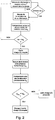
- the figures 2 and 3 show the two variants of the method of detecting the disconnection of a load, with the output (C) of the active supply stage, which can be implemented with the device represented in FIG. figure 5 .
- the first half of each flowchart relates to the detection of the existence of a variation, either of the mains voltage / current phase shift in the load, or of the cyclic ratio of the current synchronization signal. In the absence of such detection, the program operates in a loop and continues to seek the appearance of a variation of one of the two quantities mentioned above.
- the variation is measured and then compared with a threshold variation value.
- the drive switches to a state in which the output of the supply stage is cut off, then it checks that the variation is not accidental by implementing the process of the figure 1 , with a variant if U pc > U s : the load output (C) is then fed back, the variation being considered as accidental.
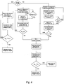
- the figure 4 shows the articulation between the processes to illustrate the overall detection process followed by a drive.
- a load output (C) fed at least one of the two methods of the invention is implemented by the drive.
- both variants are implemented in parallel.
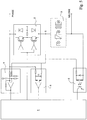
- the drive control and control unit (1) consists, for example, of a programmable microcontroller, able to control the power stage (2) to block or let the current supplying the load (3) pass.
- This unit (1) is also intended to perform the complete logic processing necessary to detect the disconnection of the load (3) (represented in its three main aspects: resistive, inductive and capacitive) placed between the output (C) of the supply stage (2) and the neutral.
- the unit (4) processes the data coming from the unit (4) for detecting overvoltages and / or the presence voltage of a load (3), as well as those coming from the detection units (5, 6) of the passage through zero respectively of the current in the load and the mains voltage.
- the unit (4) for detecting voltage across the load (3) operates by comparing a fraction (determined by a resistance bridge) of the voltage U pc between the phase and the output (C) of the stage d phase supply and a corresponding fraction of a threshold voltage U s which corresponds to approximately 160 V peak.
- this comparator shown external to the control and control unit (1), can be integrated therein.
- the unit (4) also allows the detection of overvoltages, according to the same principle of comparison to a threshold value corresponding to a peak voltage beyond which the surge is dangerous. for the drive.
- the two thresholds used are of course distinct and, assuming integration with the control and control unit, the change of threshold is managed by the program.
- the power stage (2) for supplying the load is conventionally constituted by two transistors, for example of the IGBT or MOSFET type, coupled to a diode, whose blocking / unblocking instruction is issued from the microcontroller (1).
- This conventional scheme in power electronics makes it possible to cut the phase according to the two modes used, angle conduction and angle cutoff.
- the stage (5) for detecting the zero crossing of the current in the load (3) is also based on a comparator operating in an open loop and whose inputs are respectively connected to the phase and to the load output (C). .
- the detection stage of the zero crossing of the mains voltage consists of an optocoupler whose output is connected to the microcontroller, the signal at the output of the optocoupler reflecting the phase signal and enabling the microcontroller (1) to detect the zero crossing.
Landscapes
- Circuit Arrangement For Electric Light Sources In General (AREA)
- Testing Of Short-Circuits, Discontinuities, Leakage, Or Incorrect Line Connections (AREA)
Claims (12)
- Verfahren zum Erkennen der Trennung der Leucht-Last (3) von einem Licht-Dimmer nach Art einer Stufe (2) zur variablen Versorgung durch Phasenanschnitt, die mit dem Netz verbunden ist, welche Last (3) zwischen einerseits dem Ausgang der Stufe (2) zur variablen Versorgung durch Phasenanschnitt und andererseits dem Neutralleiter angeordnet ist, welche Versorgungsstufe (2) zwischen der Netzphase und der Last (3) angeschlossen ist,
gekennzeichnet durch:- die Steuerung des Sollwerts des Stellbefehls der Versorgungsstufe (2) der Last (3);- wenn dieser Sollwert so gewählt ist, dass die Stufe (2) die Last (3) nicht versorgt:• Messen der Spannung Upc zwischen der Phase und dem Ausgang der Versorgungsstufe (2);• Vergleichen wenigstens eines Teils dieser Spannung Upc mit einem entsprechenden Teil einer vorbestimmten Schwellenspannung Us, die geringer ist als die Spitzenspannung des Netzes; und• Sperren des Dimmers (2) in dem Zustand der Nicht-Versorgung der Last (3), wenn die gemessene Spannung Upc niedriger ist als die vorbestimmte Schwellenspannung Us. - Verfahren zum Erkennen der Trennung der Licht-Last (3) von einem Licht-Dimmer nach dem vorhergehenden Anspruch, dadurch gekennzeichnet, dass der Wert der Schwellenspannung Us zwischen 50 V und 200 V Spitzenspannung liegt.
- Verfahren zum Erkennen der Trennung der Licht-Last (3) von einem Licht-Dimmer nach einem der vorhergehenden Ansprüche, dadurch gekennzeichnet, dass:
wenn der Sollwert so ist, dass die Stufe die Last versorgt:• Messen der Phasenverschiebung ϕ zwischen der Netzspannung und dem Strom, der durch die Ladung (3) für einen gegebenen Stellbefehl-Sollwert der Versorgungsstufe (2) der Ladung (3) fließt;• Erkennen und Messen der Veränderung Δϕ dieser Phasenverschiebung ϕ in Abwesenheit einer Veränderung des Sollwerts;• Vergleichen der Veränderung Δϕ der gemessenen Phasenverschiebung ϕ und eines vorbestimmten Veränderungs-Schwellenwerts Δϕs; und• Verändern des Stellbefehl-Sollwerts der Versorgungsstufe (2), um diese in einen Zustand der Nicht-Versorgung der Last (3) zu versetzen, wenn der Wert der Änderung Δϕ der gemessenen Phasenverschiebung ϕ den vorbestimmten Schwellenwert Δϕs übersteigt. - Verfahren zum Erkennen der Trennung der Licht-Last (3) von einem Licht-Dimmer nach einem der Ansprüche 1 und 2, dadurch gekennzeichnet, dass:
wenn der Sollwert so ist, dass die Stufe (2) die Ladung (3) versorgt:• Erkennen des Nulldurchgangs des Stromes in der Last (3);• Erzeugen eines resultierenden Strom-Synchronisierungssignals;• Messen des Tastverhältnisses rc des Signals;• Erkennen und Messen einer Veränderung Δrc des Tastverhältnisses rc;• Vergleichen der Veränderung Δrc des gemessenen Tastverhältnisses rc und eines vorbestimmten Veränderungs-Schwellenwerts Δrs; und• Verändern des Sollwert-Stellbefehls der Versorgungsstufe (2), um diese in einen Zustand der Nicht-Versorgung der Last (3) zu bringen, wenn der Wert der Änderung Δrc des gemessenen Tastverhältnisses rc den vorbestimmten Schwellenwert Δrs übersteigt. - Verfahren zum Erkennen der Trennung der Last (3) von einem Licht-Dimmer nach einem der Ansprüche 3 bis 4, dadurch gekennzeichnet, dass der Schwellenwert Δϕs der Phasenverschiebung ϕ zwischen ± 100 µs und ± 1 ms liegt.
- Verfahren zum Erkennen der Trennung der Last (3) von einem Licht-Dimmer nach einem der Ansprüche 3 bis 5, dadurch gekennzeichnet, dass der Änderungs-Schwellenwert Δrc des Tastverhältnisses rc zwischen 1% und 10% liegt.
- Verfahren zum Erkennen der Trennung der Last (3) von einem Licht-Dimmer nach einem der Ansprüche 3 bis 6, dadurch gekennzeichnet, dass unter der Annahme, dass der Sollwert so ist, dass die Versorgungsstufe (2) die Last (3) versorgt und dann in einen Zustand der Nicht-Versorgung infolge der Erkennung der Trennung der Last (3) versetzt wird, folgende Schritte durchgeführt werden:- eine Messung der Spannung Upc zwischen der Phase und dem Ausgang der Versorgungsstufe (2);- ein Vergleich wenigstens eines Teils dieser Spannung Upc mit einem entsprechenden Teil einer vorbestimmten Schwellenspannung Us, die niedriger ist als die Spitzenspannung des Netzes;- eine Sperrung des Dimmers in dem Zustand der Nicht-Versorgung der Last (3), wenn die gemessene Spannung Upc kleiner ist als die vorbestimmte Schwellenspannung Us; und- die erneute Anwendung des vorhergehenden Sollwert-Stellbefehls der Versorgungsstufe (2) der Last (3), wenn die gemessene Spannung Ups zwischen der Phase und dem Ausgang nicht geringer ist als die vorbestimmte Schwellenspannung Us.
- Vorrichtung zum Erkennen der Trennung der Leucht-Last (3) von einem Licht-Dimmer nach Art einer Versorgungsstufe (2), die durch Phasenanschnitt veränderbar und mit dem Netz verbunden ist, welche zur Durchführung des Verfahrens nach einem der vorhergehenden Ansprüche ausgebildet ist und eine programmierbare Einheit (1) zum Steuern und zum Regeln des Dimmers umfasst, welche die veränderbare Versorgungsstufe (2) der Last (3) durch Phasenanschnitt steuert, eine Stufe zum Erkennen von Überspannungen (4), eine Stufe zum Erkennen des Nulldurchgangs des Stromes (5) in der Last (3) und eine Stufe zum Erkennen des Nulldurchgangs der Netzspannung (6), gekennzeichnet durch eine Messstufe (4) für die Spannung zwischen der Netzphase (2) und dem Ausgang (C) der Versorgungsstufe (2).
- Vorrichtung zum Erkennen der Trennung der Leucht-Last (3) von einem Licht-Dimmer gemäß dem vorhergehenden Anspruch, dadurch gekennzeichnet, dass die Messstufe (4) einen Komparator aufweist, an dessen Eingang die Spannung Upc zwischen der Phase und dem Ausgang (C) der Versorgungsstufe (2) angelegt ist, welcher die Spannung Upc mit einem Wert der Schwellenspannung Us vergleicht.
- Vorrichtung zum Erkennen der Trennung der Leucht-Last (3) von einem Licht-Dimmer gemäß dem vorhergehenden Anspruch, dadurch gekennzeichnet, dass die Spannung Upc mit dem Komparator verbunden ist über eine Widerstandsbrücke, welche die am Eingang des Komparators anliegende Spannung aufteilt.
- Vorrichtung zum Erkennen der Trennung der Leucht-Last (3) von einem Licht-Dimmer nach einem der Ansprüche 8 bis 10, dadurch gekennzeichnet, dass die Stufe zum Erkennen von Überspannungen und die Messstufe (4) für die Spannung zwischen der Phase und dem Ausgang (C) der Versorgungsstufe (2) durch ein und denselben Schaltkreis gebildet sind.
- Vorrichtung zum Erkennen der Trennung der Leucht-Last (3) von einem Licht-Dimmer gemäß dem vorhergehenden Anspruch, dadurch gekennzeichnet, dass der Schaltkreis in eine programmierbare Einheit (1) zum Steuern und Regeln des Dimmers integriert ist und das Festlegen des Wertes der Schwellenspannung durch das Programm verwaltet wird.
Priority Applications (1)
| Application Number | Priority Date | Filing Date | Title |
|---|---|---|---|
| EP05360044.1A EP1784060B1 (de) | 2005-11-03 | 2005-11-03 | Verfahren zum Erkennen der Trennung einer Last von einem Dimmer |
Applications Claiming Priority (1)
| Application Number | Priority Date | Filing Date | Title |
|---|---|---|---|
| EP05360044.1A EP1784060B1 (de) | 2005-11-03 | 2005-11-03 | Verfahren zum Erkennen der Trennung einer Last von einem Dimmer |
Publications (2)
| Publication Number | Publication Date |
|---|---|
| EP1784060A1 EP1784060A1 (de) | 2007-05-09 |
| EP1784060B1 true EP1784060B1 (de) | 2019-05-29 |
Family
ID=36035735
Family Applications (1)
| Application Number | Title | Priority Date | Filing Date |
|---|---|---|---|
| EP05360044.1A Expired - Lifetime EP1784060B1 (de) | 2005-11-03 | 2005-11-03 | Verfahren zum Erkennen der Trennung einer Last von einem Dimmer |
Country Status (1)
| Country | Link |
|---|---|
| EP (1) | EP1784060B1 (de) |
Family Cites Families (5)
| Publication number | Priority date | Publication date | Assignee | Title |
|---|---|---|---|---|
| DE4310723A1 (de) * | 1993-04-01 | 1994-10-06 | Abb Patent Gmbh | Verfahren zur Steuerung des Wechselstroms in einem Lastkreis und Vorrichtung zur Durchführung des Verfahrens |
| DE19754866A1 (de) * | 1997-12-10 | 1999-06-17 | Siemens Ag | Universaldimmer und Verfahren zum Dimmen |
| FR2802360B1 (fr) * | 1999-12-14 | 2002-03-01 | Legrand Sa | Procede et dispositif d'alimentation electrique d'une charge par un variateur a au moins un interrupteur commande |
| DE10156686A1 (de) * | 2001-11-17 | 2003-05-28 | Merten Gmbh & Co Kg | Dimmer mit Lastart-Erkennung |
| FR2856236B1 (fr) * | 2003-06-16 | 2005-08-05 | Hager Electro Sas | Procede et dispositif d'auto-adaptation d'un variateur a une charge |
-
2005
- 2005-11-03 EP EP05360044.1A patent/EP1784060B1/de not_active Expired - Lifetime
Non-Patent Citations (1)
| Title |
|---|
| None * |
Also Published As
| Publication number | Publication date |
|---|---|
| EP1784060A1 (de) | 2007-05-09 |
Similar Documents
| Publication | Publication Date | Title |
|---|---|---|
| EP0330561B1 (de) | Mehrfunktionsregeleinrichtung mit Taktsynchronwechselstromerzeuger | |
| EP1119094B1 (de) | Verfahren und Vorrichtung zur Elektrizitätsversorgung einer Last die aus einem Dimmer mit zumindest einem kontrollierten Schalter besteht | |
| EP0240434B1 (de) | Schutzschaltung für eine Zerhackerspeisung | |
| EP0448434B1 (de) | Gleichrichter für mindestens zwei Versorgungswechselspannungsbereiche | |
| FR2756049A1 (fr) | Dispositif de detection preventive de defauts avec identification du type de charge | |
| FR3001039A1 (fr) | Procede de detection d'un defaut electrique d'un dispositif de generateur et moyens pour sa mise en oeuvre | |
| EP0166358B1 (de) | Bedienungsorgan für eine Verbindung eines elektrischen Stromkreises mit einem Netzwerk | |
| EP1271738B2 (de) | Elektronische Auslösevorrichtung mit einem Kondensator für die Stromversorgung einer Auslösespule | |
| FR2907911A1 (fr) | Controleur d'alternateur de vehicule. | |
| FR2577359A1 (fr) | Circuit de commande d'alimentation a decoupage a demarrage progressif | |
| FR2547133A1 (fr) | Circuit destine a prevenir une dissipation excessive d'energie dans les dispositifs commutateurs de puissance | |
| FR3055466A1 (fr) | Unite de controle d'un disjoncteur comportant un systeme de gestion d'alimentation electrique et disjoncteur comportant une telle unite | |
| EP0710052B1 (de) | Elektronische Startschaltung für eine Leuchtstofflampe | |
| FR2556522A1 (fr) | Redresseur de reseau pour deux tensions differentes du reseau | |
| FR2721474A1 (fr) | Dispositif de commande d'une lampe fluorescente à basse pression. | |
| FR2533774A1 (fr) | Circuit de protection pour ballast capacitif | |
| EP1784060A1 (de) | Verfahren zum Erkennen der Trennung einer Last von einem Dimmer | |
| EP1376843A2 (de) | Thyristorsteuerung für einen Brückengleichrichter | |
| EP0240402B1 (de) | Verfahren und Einrichtung zur Sendung elektrischen Stromes mit einem Transistor in eine Schaltung | |
| FR2856236A1 (fr) | Procede et dispositif d'auto-adaptation d'un variateur a une charge | |
| EP1784059B1 (de) | Verfahren zum sicheren Betrieb eines Dimmers für eine Lampe | |
| CA1227832A (fr) | Appareil de detection de la defaillance d'une alimentation electrique a decoupage | |
| FR2870996A1 (fr) | Protection de circuit electrique en mode veille pour vehicule | |
| FR2843348A1 (fr) | Circuit de protection et procede de mise en oeuvre du circuit de protection, notamment pour une protection contre les surtensions d'une commande electronique pour vehicule automobile | |
| FR2801441A1 (fr) | Dispositif ecreteur de surtensions pour un reseau de bord de vehicule, notamment automobile |
Legal Events
| Date | Code | Title | Description |
|---|---|---|---|
| PUAI | Public reference made under article 153(3) epc to a published international application that has entered the european phase |
Free format text: ORIGINAL CODE: 0009012 |
|
| AK | Designated contracting states |
Kind code of ref document: A1 Designated state(s): AT BE BG CH CY CZ DE DK EE ES FI FR GB GR HU IE IS IT LI LT LU LV MC NL PL PT RO SE SI SK TR |
|
| AX | Request for extension of the european patent |
Extension state: AL BA HR MK YU |
|
| 17P | Request for examination filed |
Effective date: 20071030 |
|
| AKX | Designation fees paid |
Designated state(s): CH DE FR LI |
|
| 17Q | First examination report despatched |
Effective date: 20080229 |
|
| GRAP | Despatch of communication of intention to grant a patent |
Free format text: ORIGINAL CODE: EPIDOSNIGR1 |
|
| INTG | Intention to grant announced |
Effective date: 20181211 |
|
| GRAS | Grant fee paid |
Free format text: ORIGINAL CODE: EPIDOSNIGR3 |
|
| GRAA | (expected) grant |
Free format text: ORIGINAL CODE: 0009210 |
|
| REG | Reference to a national code |
Ref country code: DE Ref legal event code: R081 Ref document number: 602005055857 Country of ref document: DE Owner name: HAGER CONTROLS (SOCIETE PAR ACTIONS SIMPLIFIEE, FR Free format text: FORMER OWNER: HAGER CONTROLS S.A.S., SAVERNE, FR |
|
| AK | Designated contracting states |
Kind code of ref document: B1 Designated state(s): CH DE FR LI |
|
| REG | Reference to a national code |
Ref country code: CH Ref legal event code: EP |
|
| REG | Reference to a national code |
Ref country code: DE Ref legal event code: R096 Ref document number: 602005055857 Country of ref document: DE |
|
| REG | Reference to a national code |
Ref country code: CH Ref legal event code: NV Representative=s name: RENTSCH PARTNER AG, CH |
|
| REG | Reference to a national code |
Ref country code: DE Ref legal event code: R097 Ref document number: 602005055857 Country of ref document: DE |
|
| PLBE | No opposition filed within time limit |
Free format text: ORIGINAL CODE: 0009261 |
|
| STAA | Information on the status of an ep patent application or granted ep patent |
Free format text: STATUS: NO OPPOSITION FILED WITHIN TIME LIMIT |
|
| 26N | No opposition filed |
Effective date: 20200303 |
|
| P01 | Opt-out of the competence of the unified patent court (upc) registered |
Effective date: 20230606 |
|
| PGFP | Annual fee paid to national office [announced via postgrant information from national office to epo] |
Ref country code: DE Payment date: 20241127 Year of fee payment: 20 |
|
| PGFP | Annual fee paid to national office [announced via postgrant information from national office to epo] |
Ref country code: FR Payment date: 20241126 Year of fee payment: 20 |
|
| PGFP | Annual fee paid to national office [announced via postgrant information from national office to epo] |
Ref country code: CH Payment date: 20241201 Year of fee payment: 20 |
|
| REG | Reference to a national code |
Ref country code: CH Ref legal event code: H14 Free format text: ST27 STATUS EVENT CODE: U-0-0-H10-H14 (AS PROVIDED BY THE NATIONAL OFFICE) Effective date: 20251103 Ref country code: DE Ref legal event code: R071 Ref document number: 602005055857 Country of ref document: DE |