EP1784068B1 - Flache Anzeigevorrichtung und deren Kühlgerät - Google Patents
Flache Anzeigevorrichtung und deren Kühlgerät Download PDFInfo
- Publication number
- EP1784068B1 EP1784068B1 EP06254245.1A EP06254245A EP1784068B1 EP 1784068 B1 EP1784068 B1 EP 1784068B1 EP 06254245 A EP06254245 A EP 06254245A EP 1784068 B1 EP1784068 B1 EP 1784068B1
- Authority
- EP
- European Patent Office
- Prior art keywords
- flat display
- back cover
- display device
- cross
- flow fan
- Prior art date
- Legal status (The legal status is an assumption and is not a legal conclusion. Google has not performed a legal analysis and makes no representation as to the accuracy of the status listed.)
- Not-in-force
Links
- 238000001816 cooling Methods 0.000 title description 11
- 230000002093 peripheral effect Effects 0.000 claims description 23
- 239000003381 stabilizer Substances 0.000 claims description 8
- 230000000087 stabilizing effect Effects 0.000 claims 1
- 230000017525 heat dissipation Effects 0.000 description 10
- 238000009434 installation Methods 0.000 description 6
- 230000000694 effects Effects 0.000 description 4
- 230000020169 heat generation Effects 0.000 description 4
- 238000005401 electroluminescence Methods 0.000 description 3
- 238000004519 manufacturing process Methods 0.000 description 2
- 230000004048 modification Effects 0.000 description 2
- 238000012986 modification Methods 0.000 description 2
- 229910000831 Steel Inorganic materials 0.000 description 1
- 230000006866 deterioration Effects 0.000 description 1
- 230000002542 deteriorative effect Effects 0.000 description 1
- 239000006185 dispersion Substances 0.000 description 1
- 230000002708 enhancing effect Effects 0.000 description 1
- 239000004973 liquid crystal related substance Substances 0.000 description 1
- 230000007257 malfunction Effects 0.000 description 1
- 239000011159 matrix material Substances 0.000 description 1
- 238000007789 sealing Methods 0.000 description 1
- 239000010959 steel Substances 0.000 description 1
Images



Classifications
-
- H—ELECTRICITY
- H01—ELECTRIC ELEMENTS
- H01J—ELECTRIC DISCHARGE TUBES OR DISCHARGE LAMPS
- H01J17/00—Gas-filled discharge tubes with solid cathode
- H01J17/02—Details
- H01J17/28—Cooling arrangements
-
- H—ELECTRICITY
- H05—ELECTRIC TECHNIQUES NOT OTHERWISE PROVIDED FOR
- H05K—PRINTED CIRCUITS; CASINGS OR CONSTRUCTIONAL DETAILS OF ELECTRIC APPARATUS; MANUFACTURE OF ASSEMBLAGES OF ELECTRICAL COMPONENTS
- H05K7/00—Constructional details common to different types of electric apparatus
- H05K7/20—Modifications to facilitate cooling, ventilating, or heating
- H05K7/20954—Modifications to facilitate cooling, ventilating, or heating for display panels
- H05K7/20972—Forced ventilation, e.g. on heat dissipaters coupled to components
-
- H—ELECTRICITY
- H01—ELECTRIC ELEMENTS
- H01J—ELECTRIC DISCHARGE TUBES OR DISCHARGE LAMPS
- H01J11/00—Gas-filled discharge tubes with alternating current induction of the discharge, e.g. alternating current plasma display panels [AC-PDP]; Gas-filled discharge tubes without any main electrode inside the vessel; Gas-filled discharge tubes with at least one main electrode outside the vessel
- H01J11/20—Constructional details
- H01J11/34—Vessels, containers or parts thereof, e.g. substrates
-
- Y—GENERAL TAGGING OF NEW TECHNOLOGICAL DEVELOPMENTS; GENERAL TAGGING OF CROSS-SECTIONAL TECHNOLOGIES SPANNING OVER SEVERAL SECTIONS OF THE IPC; TECHNICAL SUBJECTS COVERED BY FORMER USPC CROSS-REFERENCE ART COLLECTIONS [XRACs] AND DIGESTS
- Y10—TECHNICAL SUBJECTS COVERED BY FORMER USPC
- Y10S—TECHNICAL SUBJECTS COVERED BY FORMER USPC CROSS-REFERENCE ART COLLECTIONS [XRACs] AND DIGESTS
- Y10S345/00—Computer graphics processing and selective visual display systems
- Y10S345/905—Display device with housing structure
Definitions
- the present invention relates to a flat display device.
- the present invention also relates to a cooling apparatus for a flat display device.
- the cooling device for a flat panel display device can be operated with a low noise while quickly dissipating a large amount of internal heat to the surroundings by improving an installation structure of a fan.
- a flat display uses a driving circuit arranged in a matrix pattern to differently excite pixels and thus realize an image.
- the flat display device has been widely used as it has advantage in that it takes up a relatively small space.
- a variety of flat display modules such as a liquid crystal display (LCD), a field emission display (FED), a plasma display panel (PDP), and an electroluminescence (EL) have been applied to the flat display device.
- the flat display device using the flat display module is reduced in thickness as compared with the CRT.
- the heat which is generated by the heat-generating components in the flat display device during the operation of the flat display module, must be effectively dissipated to the surroundings.
- the display device since the image is realized by electric discharge of discharge gas, high temperature heat is generated. Therefore, if the high temperature heat is not quickly dissipated, the display device may malfunction. Needless to say, in the case of other types of flat display devices, the heat dissipation performance is very important fact determining the quality thereof.
- a heat sink is attached on a rear surface of a specific component generating a large amount of heat to cool the specific component. Furthermore, in order to generally dissipate the heat, a plurality of holes are formed on a cover of the flat display device so that cool air can pass through the holes.
- the flat display device cannot be stably operated. That is, the internal temperature of the flat display device increases to deteriorate the performance of the flat display device.
- an axial fan is installed on a rear center of a back cover in a direction perpendicular to a direction where the display device is formed.
- the axial fan forcedly exhausts the internal high temperature air of the flat display device to the surroundings through a rear side of the display device.
- a gap of ten or more centimeters must be provided between the rear surface of the display device and the wall so that the air can be exhausted.
- an overall thickness of the flat display device increases.
- the back cover Furthermore, a plurality of holes through which the air is exhausted and introduced are formed on the back cover.
- the holes of the back cover deteriorate strength of the back cover. Therefore, the back cover must be made thick. In this case, the manufacturing cost increases.
- the present invention has been made in view of the above-mentioned problems.
- Embodiments of the present invention can provide a cooling apparatus for a flat display device, which is designed to make the flat display device slimmer and effectively dissipate internal heat of the flat display device.
- Embodiments of the present invention can also provide a cooling apparatus for a flat display device, which can minimize noise and be manufactured with low costs.
- Embodiments of the present invention can further provide a cooling apparatus for a flat display device, which can minimize noise and improve heat dissipation efficiency by allowing internal air of the flat display device to be exhausted by natural convection.
- Embodiments of the present invention can provide a cooling apparatus for a flat display device, which can improve an operation reliability of the flat display device by stably supporting a cooling fan.
- a flat display device comprising: a flat display module; front and back covers defining a space for receiving the flat display module and protecting components disposed in the space, such that there is gap between a heat generating component provided on a surface of the flat display module and an inner surface of the back cover allowing air to flow through the gap to cool the heat generating component; an air inlet(16) formed on a portion of the back cover along the overall longitudinal length of the lower periphery of the back cover; an air outlet formed on an upper peripheral portion of the back cover that is inclined toward a center of the flat display module as it goes rearward, such that it can be hidden when the flat display device is viewed from a front side; a cross-flow fan disposed between an upper portion of the back cover and an upper portion of the front cover, along the overall longitudinal length of the top surface of the back cover, wherein the cross-flow fan(7) includes an impeller(10) disposed in the longitudinal direction of the back cover(4), wherein the effective exhaust area of the air outlet
- the heat dissipation efficiency can be improved and the vibration and noise caused by airflow can be reduced.
- a flat display device 1 of this embodiment includes a flat display module 2, a front cover 3 for supporting and protecting a front portion of the flat display module 2, and a back cover 4 for supporting and protecting a rear portion of the flat display module 2.
- An upper air outlet 5 through which internal hot air of the flat display device 1 exhaust is formed on an upper inclined periphery of the back cover 4.
- the flat display module 2 may be selected from the group consisting of an LCD, an FED, a PDP, and an EL.
- the flat display module 2 may be a PDP generating a large amount of heat.
- the front and back covers 3 and 4 define a space for receiving the flat display module 2 and protect components disposed in the space.
- the front and back covers 3 and 4 are independent parts that are assembled with each other.
- the embodiments of the present invention are not limited to this case.
- the front and rear covers 3 and 4 may be integrated with each other as a single body as far as they can protect the front and rear portions of the display device.
- the hot air generated from the heat generating component disposed on the rear surface of the flat display module 2 is cooled by the incoming air.
- the hot air flows upward and is exhausted through the upper air outlet 5. This is the natural convection for exhausting the hot air out of the flat display device, thereby improving the cooling efficiency.
- the external air is introduced through an overall area of the lower peripheral portion of the flat display device 1 and exhausted via an overall area of the rear portion of the display device 1.
- the upper air outlet 5 is provided on an inclined peripheral portion of the back cover so that the hot air can be exhausted upward and thus the hot air can more effectively flow.
- the heat generated from the front portion of the display module 2 can be quickly dissipated by the natural convection of the outer air.
- FIG. 2 is an exploded perspective view of the flat display device, in which the display module 2 and the front cover are in an assembled state.
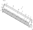
- the cross-flow fan 7 is disposed between an upper portion of the back cover 4 and an upper portion of the front cover 3.
- An air outlet channel 20 of the cross-flow fan 7 is aligned with the upper air outlet 5 of the back cover 4. Therefore, when the cross-flow fan operates, the internal hot air of the flat display device can be exhausted to the surroundings through the upper air outlet 5 of the back cover 4.
- the peripheral portion of the back cover 4 is inclined toward a center of the display device as it goes rearward, thereby defining an inclined surface 8. As the peripheral portion of the back cover 4 is inclined, it can be hidden when the flat display device is viewed from a front side, thereby not deteriorating the appearance of the display device. In addition, the inclination of the peripheral portion of the back cover 4 makes the flat display device compact. A plurality of slits is formed on the top inclined surface 8 of the peripheral portion of the back cover 4 to define the air outlet 5.
- the cross-flow fan 7 includes an impeller 10 disposed in the longitudinal direction of the back cover 4 and a circular plate 11 for dividing the impeller 10 by a predetermined interval along the longitudinal direction of the impeller 10 and enhancing strength of the impeller 10.
- the cross-flow fan 7 is further includes a driving shaft (not shown) connected to a motor 14. A rotational force of the motor 14 is transferred to the cross-flow fan via the driving shaft.
- the impeller 10 is disposed in a housing 18 to guide the airflow when the impeller 10 rotates.
- the housing 18 includes a scroll 12 disposed in front of the impeller 10 and spaced apart from the impeller 10 and a stabilizer 13 disposed in rear of the impeller 10 and spaced apart from the impeller 10.
- the impeller 10 rotates clockwise in the drawing.
- the housing 18 has upper and lower opened ends and defining an air exhaust channel 20, at a lower portion of which the impeller 10 is disposed.
- the scroll 12 is provided with a diffuser 19 that is gently curved frontward.
- the diffuser 19 disperses the air to reduce the airflow resistance and airflow noise.
- the top surface 9 of the housing 7 is inclined rearward in response to the inclined surface 8 of the back cover 4. That is, the top surface 9 of the housing 7 defines an upper end of the cross-flow fan 7.
- the top surface 9 of the housing 18 is generally inclined, it can exactly correspond to the inclined surface 8, thereby the installation space of the cross-flow fan 7 more compact.
- the air exhaust channel 20 defined between the diffuser 19 and the stabilizer 13 exactly corresponds to the air outlet 5 of the back cover 4, the air directed upward by the impeller 10 can be exhausted to the surroundings in a state where the air is widely dispersed. As a result, the airflow resistance and airflow noise can be reduced. Furthermore, since the top surface 9 of the housing 18 is inclined, the air expelled by the cross-flow fan 7 does not stay in the flat display device, thereby improving the heat dissipation efficiency and obtaining a sufficient installation space for the diffuser 19.
- the top surface 9 of the housing 18 is inclined to generally correspond to the inclined surface 8 of the back cover 4, the airflow resistance and the air leakage generated during the air flows can be more reduced.
- the top surface 9 of the housing 18 exactly corresponds to the inclined surface 8 of the back cover 4. That is, a height of the stabilizer 13 is lower than that of the scroll 12 such that the top surface 9 is inclined as it goes rearward. Thus, a height of the air outlet channel 20 is lowered as it goes rearward.
- a sealing member may be interposed between the top surface 9 and the air outlet 5 of the back cover.
- the diffuser 19 extends frontward, the dispersion effect of the air that is being exhausted can be further improved, thereby further reducing the airflow resistance and airflow noise.
- the cross-flow fan 7 can be stably installed in the back cover 4 without overlapping in the use of the space, the vibration and noise that can be generated during the operation of the cross-flow fan can be reduced.
- a rear surface of the stabilizer 13 is designed to exactly correspond to the inner surface of the back cover 4, the installation convenience of the cross-flow fan 7 can be improved and the vibration/noise can be further reduced.
- the back cover 4 is further provided with a lower air inlet 16 and a rear air inlet 17.
- the lower air inlet 16 is formed on an inclined portion of the lower periphery of the back cover 4 to introduce external cool air into the flat display device.
- the cool air introduced through the lower air inlet compensates for the hot air exhausted through the upper air outlet 5. That is, the cool air introduced compensates for a negative pressure generated by the natural convection and a negative pressure generated by the air exhausted through the upper air outlet 5.
- the cool air introduced through the lower air inlet 16 cools the components provided on the rear surface of the flat display module 2 and is then exhausted through the upper air outlet 5 via the cross-flow fan 7.
- the lower air inlet 16 is preferably formed along the overall longitudinal length of the lower periphery of the back cover 4 so that the components can be uniformly cooled. Arrows in the drawing indicates the airflow direction.
- the cross-flow fan 7 is formed along the overall longitudinal length of the top surface of the back cover 4 and the effective exhaust area of the air outlet channel 20 of the cross-flow fan is formed throughout the overall area of the top surface of the back cover 4. Therefore, the cool air introduced through the lower air inlet 16 flows upward, in the course of which the components is cooled, and is then exhausted through the upper air outlet. If the length of the cross-flow fan 7 is reduced, the heat dissipation effect at the both inner sides of the flat display device may be reduced. Nevertheless, since the effective exhaust area is large, the heat dissipation efficiency is still improved.
- a power unit i.e., a power unit
- TCP tape carrier package chip
- the components that require the thermal stability are disposed close to the lower air inlet 16 so that they can be quickly cooled by the cool air introduced.
- the components generating a large amount of heat is preferably disposed close to the cross-flow fan 7 so that the heat generated by the components can be quickly dissipated without affecting other circuits.
- the rear air inlet 17 is provided for the components where the installation location cannot be changed.
- the rear air inlet 17 is formed on a portion of the back cover 4 corresponding to a specific portion of the flat display module 2 where the heat generation components are disposed. Therefore, the heat generation components disposed corresponding to the rear air inlet 17 can be quickly cooled by the cool air introduced through the rear air inlet 17. If the installing location of the heat generation components can be changed, the rear air intake opening components may be omitted. That is, the heat generation components may be adjusted in their installing location to be closer to the cross-flow fan 7 or the lower air inlet 16.
- the cross-flow fan contacts the inner surface of the back cover 4 with a housing 18 having an inventive inclined portion, the internal hot air of the back cover can be quickly exhausted without back flows, thereby improving the heat dissipation efficiency and operational reliability of the flat display device.
- the peripheral portion of the back cover may not be inclined.
- the outlet of the air exhaust channel must contact the inner surface of the peripheral portion of the back cover so that the air exhausted through the air exhaust channel can be directly exhausted to the surroundings of the display device and the space for installing the cross-flow fan can be reduced. Therefore, when the peripheral portion of the back cover is horizontally formed without being inclined, the outlet of the air exhaust channel must be horizontal in response to the horizontal peripheral portion so that it can contact the horizontal peripheral portion.
- the inclination when the peripheral portion of the back cover is formed to be inclined, the inclination must be variously set.
- the inclination at the corner of the back cover may be higher than at the center of the back cover.
- the outlet of the air exhaust channel of the cross-flow fan and is formed corresponding to the inclination of the peripheral portion of the back cover. That is, the inclination at the corners of the outlet of the air outlet channel of the cross-flow fan is higher than that at the center portion of the outlet of the air outlet channel.
- the flat display device can be designed to be slimmer while providing a sufficient heat dissipation effect.
- the air exhaust outlet is formed in a shape similar to a cross section of the flat display device, the structure is simplified and the airflow noise can be minimized.
- the internal hot air of the flat display device can be exhausted by a negative pressure generated by the fan as well as by the natural convection, the air circulation can be effectively realized in the display device.
- the structure can be simplified and the size of the flat display device can be further reduced.
- the fan Since the fan is stably installed on an accurate position, the operational reliability of the fan can be improved.
Landscapes
- Physics & Mathematics (AREA)
- Engineering & Computer Science (AREA)
- Thermal Sciences (AREA)
- Microelectronics & Electronic Packaging (AREA)
- Plasma & Fusion (AREA)
- Devices For Indicating Variable Information By Combining Individual Elements (AREA)
- Cooling Or The Like Of Electrical Apparatus (AREA)
Claims (11)
- Flache Anzeigevorrichtung, umfassend:ein flaches Anzeigemodul (2),eine vordere und eine hintere Abdeckung (3, 4), die einen Raum zum Aufnehmen des flachen Anzeigemoduls und zum Schützen von in dem Raum angeordneten Komponenten auf eine solche Weise festlegen, dass zwischen einer Wärme erzeugenden Komponente, die auf einer Oberfläche des flachen Anzeigemoduls (2) vorgesehen ist, und einer Innenfläche der hinteren Abdeckung (4) ein Spalt vorhanden ist, wodurch ermöglicht wird, dass Luft durch den Spalt strömt, um die Wärme erzeugende Komponente zu kühlen,einen Lufteinlass (16), der auf einem Abschnitt der hinteren Abdeckung (4) entlang der in Längsrichtung verlaufenden Gesamtlänge des unteren Umfangs der hinteren Abdeckung (4) ausgebildet ist,einen Luftauslass (5), der auf einem oberen Umfangsabschnitt der hinteren Abdeckung (4) ausgebildet ist und zu einem Mittelpunkt des flachen Anzeigemoduls (2) hin geneigt ist, während er nach hinten verläuft, und zwar auf eine solche Weise, dass er unsichtbar ist, wenn die flache Anzeigevorrichtung von vorne angeschaut wird,einen Querstromventilator (7), der zwischen einem oberen Abschnitt der hinteren Abdeckung (4) und einem oberen Abschnitt der vorderen Abdeckung (3) entlang der in Längsrichtung verlaufenden Gesamtlänge der oberen Fläche der hinteren Abdeckung (4) angeordnet ist,wobei der Querstromventilator (7) ein Gebläserad (10) umfasst, das in der Längsrichtung der hinteren Abdeckung (4) angeordnet ist, undwobei die Austrittswirkfläche des Luftauslasskanals (20) des Querstromventilators über den gesamten Bereich der oberen Fläche der hinteren Abdeckung (4) ausgebildet ist.
- Flache Anzeigevorrichtung nach Anspruch 1, wobei
die vordere Abdeckung (3) einen vorderen Abschnitt des flachen Anzeigemoduls (2) hält,
wobei die hintere Abdeckung (4) einen hinteren Abschnitt des flachen Anzeigemoduls (2) hält,
wobei der untere Umfang der hinteren Abdeckung (4) zu einem Mittelpunkt des flachen Anzeigemoduls (2) hin geneigt ist, während er nach hinten verläuft, und
wobei der Querstromventilator (7) in der hinteren Abdeckung (4) angeordnet und in einer Linie mit dem oberen Umfangsabschnitt der hinteren Abdeckung (4) ausgerichtet ist. - Flache Anzeigevorrichtung nach Anspruch 2, wobei der Lufteinlass (16) auf einem unteren Umfangsabschnitt der hinteren Abdeckung (4) ausgebildet ist.
- Flache Anzeigevorrichtung nach Anspruch 2, wobei der Luftauslasskanal (20) eine Innenfläche (8) des oberen Umfangsabschnitts der hinteren Abdeckung (4) berührt.
- Flache Anzeigevorrichtung nach Anspruch 4, wobei der Luftauslasskanal (20) eine Innenfläche des oberen Umfangsabschnitts der hinteren Abdeckung (4) vollständig berührt.
- Flache Anzeigevorrichtung nach Anspruch 2, wobei der obere Umfangsabschnitt gleichmäßig geneigt ist.
- Flache Anzeigevorrichtung nach Anspruch 1, wobei der Querstromventilator (7) ferner einen Motor (14) und ein Gehäuse (18) zum Aufnehmen des Gebläserads (10) umfasst,
wobei das Gebläserad (10) mit einer Antriebswelle des Motors (14) verbunden ist,
wobei das Gehäuse (18) einen Stabilisator (13) zum Stabilisieren des Luftstroms und eine Schnecke (12) umfasst, wobei das Gebläserad (10) in einem bestimmten Abstand von dem Stabilisator (13) und der Schnecke (12) angeordnet ist, und
wobei der Luftauslasskanal (20) des Querstromventilators (7) entsprechend einer Innenfläche der Abdeckung (3, 4) ausgebildet ist. - Flache Anzeigevorrichtung nach Anspruch 7, wobei die Schnecke (12) in Reaktion auf den oberen Umfangsabschnitt der hinteren Abdeckung (4) länger als der Stabilisator (13) ist.
- Flache Anzeigevorrichtung nach Anspruch 7, wobei die Schnecke (12) auf der Vorderseite des Gebläserads (10) angeordnet ist und der Stabilisator (13) auf der Rückseite des Gebläserads (10) angeordnet ist.
- Flache Anzeigevorrichtung nach Anspruch 1, wobei der Querstromventilator (7) innerhalb des oberen Abschnitts der hinteren Abdeckung (4) angeordnet ist.
- Flache Anzeigevorrichtung nach Anspruch 1, wobei der Querstromventilator (7) in einer Linie mit dem oberen Umfangsabschnitt der hinteren Abdeckung (4) ausgerichtet ist, so dass Innenluft durch den oberen Umfangsabschnitt der hinteren Abdeckung (4) abgeführt werden kann.
Applications Claiming Priority (1)
| Application Number | Priority Date | Filing Date | Title |
|---|---|---|---|
| KR1020050105177A KR100747849B1 (ko) | 2005-11-04 | 2005-11-04 | 평면 디스플레이 기기 및 평면 디스플레이 기기의 냉각장치 |
Publications (3)
| Publication Number | Publication Date |
|---|---|
| EP1784068A2 EP1784068A2 (de) | 2007-05-09 |
| EP1784068A3 EP1784068A3 (de) | 2015-11-11 |
| EP1784068B1 true EP1784068B1 (de) | 2018-05-16 |
Family
ID=37807770
Family Applications (1)
| Application Number | Title | Priority Date | Filing Date |
|---|---|---|---|
| EP06254245.1A Not-in-force EP1784068B1 (de) | 2005-11-04 | 2006-08-11 | Flache Anzeigevorrichtung und deren Kühlgerät |
Country Status (4)
| Country | Link |
|---|---|
| US (1) | US7369407B2 (de) |
| EP (1) | EP1784068B1 (de) |
| KR (1) | KR100747849B1 (de) |
| CN (1) | CN1960614B (de) |
Families Citing this family (16)
| Publication number | Priority date | Publication date | Assignee | Title |
|---|---|---|---|---|
| KR100772247B1 (ko) * | 2005-11-04 | 2007-11-01 | 엘지전자 주식회사 | 평면 디스플레이 기기 및 평면 디스플레이 기기의 냉각장치 |
| US7463487B2 (en) * | 2005-11-04 | 2008-12-09 | Lg Electronics Inc. | Cooling apparatus for flat display device |
| KR100747820B1 (ko) * | 2005-11-04 | 2007-08-08 | 엘지전자 주식회사 | 평면 디스플레이 기기의 냉각 장치 |
| JP4273357B2 (ja) * | 2007-03-06 | 2009-06-03 | 船井電機株式会社 | 薄型表示装置の冷却ファン取付構造、及びプラズマテレビ |
| KR101456975B1 (ko) * | 2007-09-27 | 2014-10-31 | 삼성전자 주식회사 | 냉각유닛 및 이를 갖는 디스플레이장치 |
| US20100002385A1 (en) * | 2008-07-03 | 2010-01-07 | Geoff Lyon | Electronic device having active noise control and a port ending with curved lips |
| US20120236499A1 (en) * | 2009-12-03 | 2012-09-20 | Panasonic Corporation | Radiation unit of electronic device and electronic device using same |
| US20160014910A1 (en) * | 2014-07-10 | 2016-01-14 | Peerless Industries, Inc. | Enclosed media device with improved heat transfer capabilities |
| TWI563908B (en) * | 2015-01-09 | 2016-12-21 | Young Lighting Technology Inc | Display having fan |
| KR101694008B1 (ko) * | 2015-06-16 | 2017-01-09 | 현대자동차주식회사 | 열전 제습 장치 |
| US20170130948A1 (en) * | 2015-11-05 | 2017-05-11 | Litemax Electronics Inc. | High -brightness panel heat-dissipating apparatus |
| WO2017138202A1 (ja) * | 2016-02-09 | 2017-08-17 | ソニー株式会社 | 表示装置 |
| CN109644548B (zh) * | 2016-05-02 | 2021-04-30 | 海别得公司 | 冷却等离子切割系统及相关的系统和方法 |
| US10321615B2 (en) | 2016-06-16 | 2019-06-11 | Microsoft Technology Licensing, Llc | Display module with integrated thermal management structure |
| KR102560667B1 (ko) * | 2018-07-23 | 2023-07-27 | 엘지전자 주식회사 | 디스플레이 디바이스 |
| KR102575515B1 (ko) * | 2018-12-19 | 2023-09-05 | 엘지디스플레이 주식회사 | 디스플레이 장치 |
Family Cites Families (21)
| Publication number | Priority date | Publication date | Assignee | Title |
|---|---|---|---|---|
| JPH0775939B2 (ja) * | 1987-10-30 | 1995-08-16 | 松下電器産業株式会社 | 自動車用空気調和装置 |
| US4951737A (en) * | 1988-10-31 | 1990-08-28 | Amana Refrigeration, Inc. | Modular blower and heater assembly for air conditioner |
| CA2028374C (en) * | 1989-10-25 | 1994-03-29 | Toru Ichikawa | Automobile air conditioner |
| US5335721A (en) * | 1990-02-12 | 1994-08-09 | Inter-City Products Corporation (Usa) | Air conditioner modular unit with dual cross flow blowers |
| JP3234740B2 (ja) * | 1994-06-09 | 2001-12-04 | キヤノン株式会社 | 画像表示装置 |
| JPH10117079A (ja) * | 1996-10-09 | 1998-05-06 | Fujitsu General Ltd | 電子機器のファン取付構造 |
| JP2000156581A (ja) * | 1998-11-20 | 2000-06-06 | Fujitsu General Ltd | プラズマディスプレイの放熱装置 |
| JP4532679B2 (ja) * | 2000-06-20 | 2010-08-25 | キヤノン株式会社 | 表示装置 |
| US6493440B2 (en) * | 2001-04-23 | 2002-12-10 | Gilbarco Inc. | Thermal management for a thin environmentally-sealed LCD display enclosure |
| JP2003029648A (ja) * | 2001-07-16 | 2003-01-31 | Sanyo Electric Co Ltd | プラズマディスプレイ |
| TW583529B (en) * | 2001-11-15 | 2004-04-11 | Wistron Corp | Liquid crystal display computer with a removable device frame |
| US20040223299A1 (en) * | 2003-05-07 | 2004-11-11 | Prosenjit Ghosh | Display cooling |
| US20050105012A1 (en) * | 2003-10-28 | 2005-05-19 | Kim Sung K. | Display |
| CN1332590C (zh) * | 2004-04-02 | 2007-08-15 | 乐金电子(南京)等离子有限公司 | 平面显示器噪音防止装置 |
| KR100638047B1 (ko) * | 2004-10-15 | 2006-10-23 | 엘지전자 주식회사 | 백라이트 유닛을 갖는 액정 디스플레이 |
| JP2006152921A (ja) * | 2004-11-29 | 2006-06-15 | Sony Corp | 冷却用送風ファン及び映像表示装置 |
| KR100649598B1 (ko) * | 2004-12-29 | 2006-11-27 | 엘지전자 주식회사 | 플라즈마 디스플레이 패널 텔레비전의 방열구조 |
| KR100747820B1 (ko) * | 2005-11-04 | 2007-08-08 | 엘지전자 주식회사 | 평면 디스플레이 기기의 냉각 장치 |
| US7463487B2 (en) * | 2005-11-04 | 2008-12-09 | Lg Electronics Inc. | Cooling apparatus for flat display device |
| KR100731366B1 (ko) * | 2005-11-04 | 2007-06-21 | 엘지전자 주식회사 | 평면 디스플레이 기기의 냉각 장치 및 그 장치의 횡류팬 |
| KR100772247B1 (ko) * | 2005-11-04 | 2007-11-01 | 엘지전자 주식회사 | 평면 디스플레이 기기 및 평면 디스플레이 기기의 냉각장치 |
-
2005
- 2005-11-04 KR KR1020050105177A patent/KR100747849B1/ko not_active Expired - Fee Related
-
2006
- 2006-08-08 US US11/500,481 patent/US7369407B2/en active Active
- 2006-08-11 EP EP06254245.1A patent/EP1784068B1/de not_active Not-in-force
- 2006-09-06 CN CN2006101281563A patent/CN1960614B/zh not_active Expired - Fee Related
Non-Patent Citations (1)
| Title |
|---|
| None * |
Also Published As
| Publication number | Publication date |
|---|---|
| US20070103865A1 (en) | 2007-05-10 |
| US7369407B2 (en) | 2008-05-06 |
| KR100747849B1 (ko) | 2007-08-08 |
| CN1960614B (zh) | 2011-06-01 |
| KR20070048298A (ko) | 2007-05-09 |
| EP1784068A3 (de) | 2015-11-11 |
| EP1784068A2 (de) | 2007-05-09 |
| CN1960614A (zh) | 2007-05-09 |
Similar Documents
| Publication | Publication Date | Title |
|---|---|---|
| US7463487B2 (en) | Cooling apparatus for flat display device | |
| US7492589B2 (en) | Cooling apparatus for flat display device | |
| EP1784068B1 (de) | Flache Anzeigevorrichtung und deren Kühlgerät | |
| KR100747848B1 (ko) | 평면 디스플레이 기기의 냉각 장치 | |
| EP1784070B1 (de) | Flache Anzeigevorrichtung und deren Kühlgerät | |
| EP1783799B1 (de) | Kühlsystem für Flach-Bildschirm und sein Querstromventilator | |
| JP2001326488A (ja) | 電子機器 | |
| JP2011034309A (ja) | 電子機器 | |
| KR100805400B1 (ko) | 평면 디스플레이 기기의 냉각 장치 | |
| KR20040044705A (ko) | 전기전자기기의 냉각장치 및 이를 장착한 전기전자기기 | |
| CN210864590U (zh) | 一种辅助散热式一体机 | |
| KR20050045141A (ko) | 플라즈마 디스플레이 장치 | |
| CN100452120C (zh) | 等离子体显示装置 | |
| KR100731382B1 (ko) | 평면 디스플레이 기기의 냉각 장치 | |
| JPH06195155A (ja) | 筐体空冷ユニット | |
| KR100831780B1 (ko) | 디스플레이 기기 | |
| KR100751113B1 (ko) | 평면 디스플레이 기기 및 그 기기의 설치장치 | |
| US20080062387A1 (en) | Electronic device and projector | |
| CN117812872A (zh) | 显示装置 | |
| JP2006134981A (ja) | 冷却装置及びそれを備えた電子機器 | |
| KR20090040687A (ko) | 평면 디스플레이 기기 및 그 평면 디스플레이 기기의냉각장치 | |
| KR20060037023A (ko) | 플라즈마 디스플레이 장치 | |
| KR20070009172A (ko) | 블로어 팬을 이용한 램프 냉각 장치 |
Legal Events
| Date | Code | Title | Description |
|---|---|---|---|
| PUAI | Public reference made under article 153(3) epc to a published international application that has entered the european phase |
Free format text: ORIGINAL CODE: 0009012 |
|
| AK | Designated contracting states |
Kind code of ref document: A2 Designated state(s): AT BE BG CH CY CZ DE DK EE ES FI FR GB GR HU IE IS IT LI LT LU LV MC NL PL PT RO SE SI SK TR |
|
| AX | Request for extension of the european patent |
Extension state: AL BA HR MK YU |
|
| PUAL | Search report despatched |
Free format text: ORIGINAL CODE: 0009013 |
|
| AK | Designated contracting states |
Kind code of ref document: A3 Designated state(s): AT BE BG CH CY CZ DE DK EE ES FI FR GB GR HU IE IS IT LI LT LU LV MC NL PL PT RO SE SI SK TR |
|
| AX | Request for extension of the european patent |
Extension state: AL BA HR MK RS |
|
| RIC1 | Information provided on ipc code assigned before grant |
Ipc: H05K 7/20 20060101AFI20151006BHEP |
|
| 17P | Request for examination filed |
Effective date: 20160414 |
|
| RBV | Designated contracting states (corrected) |
Designated state(s): AT BE BG CH CY CZ DE DK EE ES FI FR GB GR HU IE IS IT LI LT LU LV MC NL PL PT RO SE SI SK TR |
|
| RBV | Designated contracting states (corrected) |
Designated state(s): AT BE BG CH CY CZ DE DK EE ES FI FR GB GR HU IE IS IT LI LT LU LV MC NL PL PT RO SE SI SK TR |
|
| AKX | Designation fees paid |
Designated state(s): AT BE BG CH CY CZ DE DK EE ES FI FR GB GR HU IE IS IT LI LT LU LV MC NL PL PT RO SE SI SK TR |
|
| AXX | Extension fees paid |
Extension state: BA Extension state: RS Extension state: HR Extension state: AL Extension state: MK |
|
| 17Q | First examination report despatched |
Effective date: 20161125 |
|
| GRAP | Despatch of communication of intention to grant a patent |
Free format text: ORIGINAL CODE: EPIDOSNIGR1 |
|
| INTG | Intention to grant announced |
Effective date: 20180125 |
|
| GRAS | Grant fee paid |
Free format text: ORIGINAL CODE: EPIDOSNIGR3 |
|
| GRAA | (expected) grant |
Free format text: ORIGINAL CODE: 0009210 |
|
| AK | Designated contracting states |
Kind code of ref document: B1 Designated state(s): AT BE BG CH CY CZ DE DK EE ES FI FR GB GR HU IE IS IT LI LT LU LV MC NL PL PT RO SE SI SK TR |
|
| REG | Reference to a national code |
Ref country code: GB Ref legal event code: FG4D |
|
| REG | Reference to a national code |
Ref country code: CH Ref legal event code: EP |
|
| REG | Reference to a national code |
Ref country code: DE Ref legal event code: R096 Ref document number: 602006055388 Country of ref document: DE |
|
| REG | Reference to a national code |
Ref country code: IE Ref legal event code: FG4D |
|
| REG | Reference to a national code |
Ref country code: AT Ref legal event code: REF Ref document number: 1000723 Country of ref document: AT Kind code of ref document: T Effective date: 20180615 |
|
| REG | Reference to a national code |
Ref country code: FR Ref legal event code: PLFP Year of fee payment: 13 |
|
| REG | Reference to a national code |
Ref country code: NL Ref legal event code: MP Effective date: 20180516 |
|
| REG | Reference to a national code |
Ref country code: LT Ref legal event code: MG4D |
|
| PG25 | Lapsed in a contracting state [announced via postgrant information from national office to epo] |
Ref country code: BG Free format text: LAPSE BECAUSE OF FAILURE TO SUBMIT A TRANSLATION OF THE DESCRIPTION OR TO PAY THE FEE WITHIN THE PRESCRIBED TIME-LIMIT Effective date: 20180816 Ref country code: FI Free format text: LAPSE BECAUSE OF FAILURE TO SUBMIT A TRANSLATION OF THE DESCRIPTION OR TO PAY THE FEE WITHIN THE PRESCRIBED TIME-LIMIT Effective date: 20180516 Ref country code: SE Free format text: LAPSE BECAUSE OF FAILURE TO SUBMIT A TRANSLATION OF THE DESCRIPTION OR TO PAY THE FEE WITHIN THE PRESCRIBED TIME-LIMIT Effective date: 20180516 Ref country code: LT Free format text: LAPSE BECAUSE OF FAILURE TO SUBMIT A TRANSLATION OF THE DESCRIPTION OR TO PAY THE FEE WITHIN THE PRESCRIBED TIME-LIMIT Effective date: 20180516 Ref country code: ES Free format text: LAPSE BECAUSE OF FAILURE TO SUBMIT A TRANSLATION OF THE DESCRIPTION OR TO PAY THE FEE WITHIN THE PRESCRIBED TIME-LIMIT Effective date: 20180516 |
|
| PG25 | Lapsed in a contracting state [announced via postgrant information from national office to epo] |
Ref country code: GR Free format text: LAPSE BECAUSE OF FAILURE TO SUBMIT A TRANSLATION OF THE DESCRIPTION OR TO PAY THE FEE WITHIN THE PRESCRIBED TIME-LIMIT Effective date: 20180817 Ref country code: NL Free format text: LAPSE BECAUSE OF FAILURE TO SUBMIT A TRANSLATION OF THE DESCRIPTION OR TO PAY THE FEE WITHIN THE PRESCRIBED TIME-LIMIT Effective date: 20180516 Ref country code: LV Free format text: LAPSE BECAUSE OF FAILURE TO SUBMIT A TRANSLATION OF THE DESCRIPTION OR TO PAY THE FEE WITHIN THE PRESCRIBED TIME-LIMIT Effective date: 20180516 |
|
| REG | Reference to a national code |
Ref country code: AT Ref legal event code: MK05 Ref document number: 1000723 Country of ref document: AT Kind code of ref document: T Effective date: 20180516 |
|
| PG25 | Lapsed in a contracting state [announced via postgrant information from national office to epo] |
Ref country code: RO Free format text: LAPSE BECAUSE OF FAILURE TO SUBMIT A TRANSLATION OF THE DESCRIPTION OR TO PAY THE FEE WITHIN THE PRESCRIBED TIME-LIMIT Effective date: 20180516 Ref country code: SK Free format text: LAPSE BECAUSE OF FAILURE TO SUBMIT A TRANSLATION OF THE DESCRIPTION OR TO PAY THE FEE WITHIN THE PRESCRIBED TIME-LIMIT Effective date: 20180516 Ref country code: CZ Free format text: LAPSE BECAUSE OF FAILURE TO SUBMIT A TRANSLATION OF THE DESCRIPTION OR TO PAY THE FEE WITHIN THE PRESCRIBED TIME-LIMIT Effective date: 20180516 Ref country code: EE Free format text: LAPSE BECAUSE OF FAILURE TO SUBMIT A TRANSLATION OF THE DESCRIPTION OR TO PAY THE FEE WITHIN THE PRESCRIBED TIME-LIMIT Effective date: 20180516 Ref country code: AT Free format text: LAPSE BECAUSE OF FAILURE TO SUBMIT A TRANSLATION OF THE DESCRIPTION OR TO PAY THE FEE WITHIN THE PRESCRIBED TIME-LIMIT Effective date: 20180516 Ref country code: DK Free format text: LAPSE BECAUSE OF FAILURE TO SUBMIT A TRANSLATION OF THE DESCRIPTION OR TO PAY THE FEE WITHIN THE PRESCRIBED TIME-LIMIT Effective date: 20180516 Ref country code: PL Free format text: LAPSE BECAUSE OF FAILURE TO SUBMIT A TRANSLATION OF THE DESCRIPTION OR TO PAY THE FEE WITHIN THE PRESCRIBED TIME-LIMIT Effective date: 20180516 |
|
| REG | Reference to a national code |
Ref country code: DE Ref legal event code: R097 Ref document number: 602006055388 Country of ref document: DE |
|
| PG25 | Lapsed in a contracting state [announced via postgrant information from national office to epo] |
Ref country code: IT Free format text: LAPSE BECAUSE OF FAILURE TO SUBMIT A TRANSLATION OF THE DESCRIPTION OR TO PAY THE FEE WITHIN THE PRESCRIBED TIME-LIMIT Effective date: 20180516 |
|
| PLBE | No opposition filed within time limit |
Free format text: ORIGINAL CODE: 0009261 |
|
| STAA | Information on the status of an ep patent application or granted ep patent |
Free format text: STATUS: NO OPPOSITION FILED WITHIN TIME LIMIT |
|
| PG25 | Lapsed in a contracting state [announced via postgrant information from national office to epo] |
Ref country code: MC Free format text: LAPSE BECAUSE OF FAILURE TO SUBMIT A TRANSLATION OF THE DESCRIPTION OR TO PAY THE FEE WITHIN THE PRESCRIBED TIME-LIMIT Effective date: 20180516 |
|
| REG | Reference to a national code |
Ref country code: CH Ref legal event code: PL |
|
| 26N | No opposition filed |
Effective date: 20190219 |
|
| PG25 | Lapsed in a contracting state [announced via postgrant information from national office to epo] |
Ref country code: LI Free format text: LAPSE BECAUSE OF NON-PAYMENT OF DUE FEES Effective date: 20180831 Ref country code: CH Free format text: LAPSE BECAUSE OF NON-PAYMENT OF DUE FEES Effective date: 20180831 Ref country code: LU Free format text: LAPSE BECAUSE OF NON-PAYMENT OF DUE FEES Effective date: 20180811 |
|
| REG | Reference to a national code |
Ref country code: BE Ref legal event code: MM Effective date: 20180831 |
|
| REG | Reference to a national code |
Ref country code: IE Ref legal event code: MM4A |
|
| PG25 | Lapsed in a contracting state [announced via postgrant information from national office to epo] |
Ref country code: SI Free format text: LAPSE BECAUSE OF FAILURE TO SUBMIT A TRANSLATION OF THE DESCRIPTION OR TO PAY THE FEE WITHIN THE PRESCRIBED TIME-LIMIT Effective date: 20180516 |
|
| PG25 | Lapsed in a contracting state [announced via postgrant information from national office to epo] |
Ref country code: IE Free format text: LAPSE BECAUSE OF NON-PAYMENT OF DUE FEES Effective date: 20180811 |
|
| PG25 | Lapsed in a contracting state [announced via postgrant information from national office to epo] |
Ref country code: BE Free format text: LAPSE BECAUSE OF NON-PAYMENT OF DUE FEES Effective date: 20180831 |
|
| PG25 | Lapsed in a contracting state [announced via postgrant information from national office to epo] |
Ref country code: TR Free format text: LAPSE BECAUSE OF FAILURE TO SUBMIT A TRANSLATION OF THE DESCRIPTION OR TO PAY THE FEE WITHIN THE PRESCRIBED TIME-LIMIT Effective date: 20180516 |
|
| PG25 | Lapsed in a contracting state [announced via postgrant information from national office to epo] |
Ref country code: PT Free format text: LAPSE BECAUSE OF FAILURE TO SUBMIT A TRANSLATION OF THE DESCRIPTION OR TO PAY THE FEE WITHIN THE PRESCRIBED TIME-LIMIT Effective date: 20180516 Ref country code: HU Free format text: LAPSE BECAUSE OF FAILURE TO SUBMIT A TRANSLATION OF THE DESCRIPTION OR TO PAY THE FEE WITHIN THE PRESCRIBED TIME-LIMIT; INVALID AB INITIO Effective date: 20060811 |
|
| PG25 | Lapsed in a contracting state [announced via postgrant information from national office to epo] |
Ref country code: CY Free format text: LAPSE BECAUSE OF FAILURE TO SUBMIT A TRANSLATION OF THE DESCRIPTION OR TO PAY THE FEE WITHIN THE PRESCRIBED TIME-LIMIT Effective date: 20180516 |
|
| PG25 | Lapsed in a contracting state [announced via postgrant information from national office to epo] |
Ref country code: IS Free format text: LAPSE BECAUSE OF FAILURE TO SUBMIT A TRANSLATION OF THE DESCRIPTION OR TO PAY THE FEE WITHIN THE PRESCRIBED TIME-LIMIT Effective date: 20180916 |
|
| PGFP | Annual fee paid to national office [announced via postgrant information from national office to epo] |
Ref country code: DE Payment date: 20200706 Year of fee payment: 15 Ref country code: GB Payment date: 20200709 Year of fee payment: 15 Ref country code: FR Payment date: 20200709 Year of fee payment: 15 |
|
| REG | Reference to a national code |
Ref country code: DE Ref legal event code: R119 Ref document number: 602006055388 Country of ref document: DE |
|
| GBPC | Gb: european patent ceased through non-payment of renewal fee |
Effective date: 20210811 |
|
| PG25 | Lapsed in a contracting state [announced via postgrant information from national office to epo] |
Ref country code: GB Free format text: LAPSE BECAUSE OF NON-PAYMENT OF DUE FEES Effective date: 20210811 Ref country code: FR Free format text: LAPSE BECAUSE OF NON-PAYMENT OF DUE FEES Effective date: 20210831 Ref country code: DE Free format text: LAPSE BECAUSE OF NON-PAYMENT OF DUE FEES Effective date: 20220301 |