EP1784576B2 - Refroidissement de rotors de pompe - Google Patents
Refroidissement de rotors de pompe Download PDFInfo
- Publication number
- EP1784576B2 EP1784576B2 EP05772932.9A EP05772932A EP1784576B2 EP 1784576 B2 EP1784576 B2 EP 1784576B2 EP 05772932 A EP05772932 A EP 05772932A EP 1784576 B2 EP1784576 B2 EP 1784576B2
- Authority
- EP
- European Patent Office
- Prior art keywords
- tube
- coolant
- rotor
- rotor according
- cavity
- Prior art date
- Legal status (The legal status is an assumption and is not a legal conclusion. Google has not performed a legal analysis and makes no representation as to the accuracy of the status listed.)
- Expired - Lifetime
Links
Images


Classifications
-
- F—MECHANICAL ENGINEERING; LIGHTING; HEATING; WEAPONS; BLASTING
- F04—POSITIVE - DISPLACEMENT MACHINES FOR LIQUIDS; PUMPS FOR LIQUIDS OR ELASTIC FLUIDS
- F04C—ROTARY-PISTON, OR OSCILLATING-PISTON, POSITIVE-DISPLACEMENT MACHINES FOR LIQUIDS; ROTARY-PISTON, OR OSCILLATING-PISTON, POSITIVE-DISPLACEMENT PUMPS
- F04C29/00—Component parts, details or accessories of pumps or pumping installations, not provided for in groups F04C18/00 - F04C28/00
- F04C29/04—Heating; Cooling; Heat insulation
-
- F—MECHANICAL ENGINEERING; LIGHTING; HEATING; WEAPONS; BLASTING
- F04—POSITIVE - DISPLACEMENT MACHINES FOR LIQUIDS; PUMPS FOR LIQUIDS OR ELASTIC FLUIDS
- F04C—ROTARY-PISTON, OR OSCILLATING-PISTON, POSITIVE-DISPLACEMENT MACHINES FOR LIQUIDS; ROTARY-PISTON, OR OSCILLATING-PISTON, POSITIVE-DISPLACEMENT PUMPS
- F04C18/00—Rotary-piston pumps specially adapted for elastic fluids
- F04C18/08—Rotary-piston pumps specially adapted for elastic fluids of intermeshing-engagement type, i.e. with engagement of co-operating members similar to that of toothed gearing
- F04C18/082—Details specially related to intermeshing engagement type pumps
- F04C18/084—Toothed wheels
-
- F—MECHANICAL ENGINEERING; LIGHTING; HEATING; WEAPONS; BLASTING
- F04—POSITIVE - DISPLACEMENT MACHINES FOR LIQUIDS; PUMPS FOR LIQUIDS OR ELASTIC FLUIDS
- F04C—ROTARY-PISTON, OR OSCILLATING-PISTON, POSITIVE-DISPLACEMENT MACHINES FOR LIQUIDS; ROTARY-PISTON, OR OSCILLATING-PISTON, POSITIVE-DISPLACEMENT PUMPS
- F04C18/00—Rotary-piston pumps specially adapted for elastic fluids
- F04C18/08—Rotary-piston pumps specially adapted for elastic fluids of intermeshing-engagement type, i.e. with engagement of co-operating members similar to that of toothed gearing
- F04C18/12—Rotary-piston pumps specially adapted for elastic fluids of intermeshing-engagement type, i.e. with engagement of co-operating members similar to that of toothed gearing of other than internal-axis type
- F04C18/14—Rotary-piston pumps specially adapted for elastic fluids of intermeshing-engagement type, i.e. with engagement of co-operating members similar to that of toothed gearing of other than internal-axis type with toothed rotary pistons
- F04C18/16—Rotary-piston pumps specially adapted for elastic fluids of intermeshing-engagement type, i.e. with engagement of co-operating members similar to that of toothed gearing of other than internal-axis type with toothed rotary pistons with helical teeth, e.g. chevron-shaped, screw type
-
- F—MECHANICAL ENGINEERING; LIGHTING; HEATING; WEAPONS; BLASTING
- F04—POSITIVE - DISPLACEMENT MACHINES FOR LIQUIDS; PUMPS FOR LIQUIDS OR ELASTIC FLUIDS
- F04C—ROTARY-PISTON, OR OSCILLATING-PISTON, POSITIVE-DISPLACEMENT MACHINES FOR LIQUIDS; ROTARY-PISTON, OR OSCILLATING-PISTON, POSITIVE-DISPLACEMENT PUMPS
- F04C2240/00—Components
- F04C2240/60—Shafts
- F04C2240/603—Shafts with internal channels for fluid distribution, e.g. hollow shaft
-
- F—MECHANICAL ENGINEERING; LIGHTING; HEATING; WEAPONS; BLASTING
- F04—POSITIVE - DISPLACEMENT MACHINES FOR LIQUIDS; PUMPS FOR LIQUIDS OR ELASTIC FLUIDS
- F04C—ROTARY-PISTON, OR OSCILLATING-PISTON, POSITIVE-DISPLACEMENT MACHINES FOR LIQUIDS; ROTARY-PISTON, OR OSCILLATING-PISTON, POSITIVE-DISPLACEMENT PUMPS
- F04C29/00—Component parts, details or accessories of pumps or pumping installations, not provided for in groups F04C18/00 - F04C28/00
- F04C29/02—Lubrication; Lubricant separation
- F04C29/023—Lubricant distribution through a hollow driving shaft
Definitions
- the present invention relates to the cooling of pump rotors, and in particular to the cooling of the rotors of a screw pump.
- Screw pumps are widely used in industrial processes to provide a clean and/or low pressure environment for the manufacture of products. Applications include the pharmaceutical and semiconductor manufacturing industries.
- a typical screw pump mechanism comprises two spaced parallel shafts each carrying externally threaded rotors, the shafts being mounted in a pump body such that the threads of the rotors intermesh. Close tolerances between the rotor threads at the points of intermeshing and with the internal surface of the pump body (which acts as a stator) cause volumes of gas entering at an inlet to be trapped between the threads of the rotors and the internal surface and thereby urged towards an outlet of the pump as the rotors rotate.
- FIG 1 illustrates schematically one known arrangement for cooling an outlet section of a double-ended rotor of a screw pump, as illustrated in our earlier International patent application no. WO 2004/036049 .
- a central cavity 10 is formed in each end of the threaded body 12 of the rotor (one end only shown in Figure 1 ), the cavity 10 being co-axial with the body 12, the longitudinal axis of which is indicated at 14.
- a shaft 16 is attached to the body 12 by means of bolts 18 such that the shaft 16 extends into the cavity 10 and rotates with the body 12 of the rotor during use.
- the shaft 16 has a first central bore 20 formed therein.
- the first bore 20 houses a coolant supply tube 22 for supplying coolant pumped from a source thereof into a second central bore 24 of the shaft 16, the second bore 24 being co-axial with the first bore 20.
- the coolant flows from the second bore 24 into the cavity 10, wherein the coolant flows radially outwards between the end 26 of the shaft 16 and the end wall 28 of the cavity 10, and then flows away from the end wall 28 within a narrow annular gap 30 located between the cylindrical wall 32 of the shaft 16 and the cylindrical wall 34 of the cavity 10.
- Radial bores 36 formed in the shaft 16 allow the coolant to flow into the first bore 20 of the shaft 16 and back towards the end 38 of the shaft 16, from which it is discharged into a reservoir (not shown) with a pumping mechanism for returning the coolant to the supply tube 22.
- US 5,662,463 discloses a rotor for a vacuum pump, the rotor comprising a threaded body, a cavity extending axially along into the body, means for supplying lubricant to the cavity, means for discharging lubricant from the cavity, and a bearing bracket located within the cavity for supporting the body for rotation about the bracket.
- the lubricant is supplied to grooved in the bearing bracket for lubricating between an outer surface of the bearing bracket and an inner surface of the body.
- the present invention provides a rotor for a vacuum pump as defined in the claims appended hereto.
- the heated surface of the rotor that is exposed for cooling by the coolant is limited to the surface area of the cylindrical wall 34 of the cavity 10.
- the present invention dispenses with the annular gap 30 of the prior art and instead provides a flow guide that is closely adjacent, preferably in contact with, the body and which defines within the cavity a bore and a plurality of slots extending along the flow guide and radially spaced from the bore.
- a flow guide that is closely adjacent, preferably in contact with, the body and which defines within the cavity a bore and a plurality of slots extending along the flow guide and radially spaced from the bore.
- the heated surface now exposed for cooling includes both the surface area of the inner surface of the guide, which defines the bore, and the sum of the surface areas of the walls of the slots, so that heat can be extracted from the rotor by coolant as it flows both into the rotor and out from the rotor. This can significantly increase the surface area for cooling in comparison to a prior art arrangement having a similar sized cavity formed in the rotor body.
- the guiding means is preferably formed from different material than the rotor body.
- at least part of the guiding means is preferably formed from material having a thermal conductivity equal to or greater than that of the material from which the rotor body is formed.
- the guiding means is preferably formed from aluminium or an alloy thereof, copper or an alloy thereof, or any other suitable material having a thermal conductivity equal to or greater than that of iron.
- the guide means preferably defines within each cavity a coolant flow path extending between the supply means and the discharge means.
- the coolant flow path preferably has a first portion along which coolant flows in a first direction and a second portion along which coolant flows in a second direction opposite to the first.
- the guide means preferably comprises, within each cavity, a tube for defining the first and second portions of the flow path.
- the first portion of the flow path may extend between the body and the outer wall of the tube, and the second portion of the flow path may extend within the bore of the tube.
- Each tube preferably comprises one or more radial bores for linking the first portion of the flow path to the second portion of the flow.
- the supply means is preferably arranged to supply coolant to the first portion of the flow path, and the discharge means is preferably arranged to receive coolant from the second portion of the flow path.
- FIG. 2 illustrates part of the embodiment of a rotor 100 of a screw pump.
- the rotor 100 comprises a threaded body 102 having a longitudinal axis 104.
- a cavity 106 is formed in the body 102 such that the cavity 106 extends partially into and is substantially co-axial with the body 102.
- a tube 108 is located within the cavity 106, co-axial with the body 102, such that the outer surface 110 of the tube 108 forms an interference fit with the cylindrical wall 112 of the cavity 106.
- the tube 108 may be inserted in the cavity 106 using any convenient technique, such as shrink fitting in which the tube 108 is initially shrunk using liquid nitrogen, for example, and inserted into the cavity 106 so that subsequent thermal expansion causes the tube 108 to be rigidly located within the cavity 106.
- the tube 108 is preferably formed, at least in part, from material that has a thermal conductivity that is at least equal to that of the material from which the body 102 is formed.
- the body 102 is formed from iron
- the tube 108 is formed from an aluminium alloy.
- the inner, cylindrical surface 114 of the tube 108 defines a bore 116 extending into the cavity 106 substantially co-axial with the body 102.
- a plurality of grooves 118 are machined or otherwise formed on the outer surface 110 of the tube 108, each groove 118 extending along the length of the tube 108. In the preferred embodiment, each groove 118 extends substantially parallel to the longitudinal axis 104 of the body, although part of the each groove 118 may be curved or otherwise shaped as required.
- the grooves 118 define with the wall 112 of the cavity a plurality of axially extending slots 119 surrounding the bore 116 of the tube 108. As shown in Figure 2(a) , the tube 108 is not inserted fully into the cavity 106 so that the slots 119 are in fluid communication with the bore 116.
- a shaft 120 extends partially into the bore 116 of the tube 108, and is attached to the body 102 by means of bolts 122 or the like. As indicated in Figure 2(a) , the shaft 120 is co-axial with the body 102. The shaft 120 is machined such that a cylindrical outer surface 124 of the end 126 of the shaft 120 that extends into the bore 116 engages the inner surface 114 of the tube 108.
- the shaft 120 includes a longitudinal bore 128 that passes along the length of the shaft 120 and is co-axial therewith.
- the longitudinal bore 128 has a constant diameter along the majority of the shaft 120, the diameter reducing towards the end 126 of the shaft 120 to define a reduced-diameter section 130 of the longitudinal bore 128.
- a coolant supply tube 132 is located within the longitudinal bore 128.
- the coolant supply tube 132 has an outer diameter that is slightly less than that of the reduced-diameter section 130 of the longitudinal bore 128.
- the coolant supply tube 132 extends through the longitudinal bore 128 such that a first end 134 is located within the bore 116 and a second end thereof (not shown) extends from the other end (not shown) of the shaft 120.
- the second end of the coolant supply tube may be retained by any convenient means.
- a plain bearing is provided between the reduced-diameter section 130 of the longitudinal bore 128 and the coolant supply tube 132.
- the shaft 120 further includes a plurality of second bores 136, each extending between the longitudinal bore 128 and an annular recess or channel 138 formed in the shaft 102 and radially aligned with the slots 119.
- the longitudinal axis 140 of each second bore 136 is at an acute angle to the longitudinal axis 104 of the rotor 100. In this example, this acute angle is approximately 30°, although any convenient value for this angle may be chosen.
- a stream of coolant for example a coolant oil
- a source thereof to the second end of the coolant supply tube 132.
- the source may be conveniently provided by an oil reservoir located external to the stator of the pump in which the rotor is housed.
- the coolant flows through the bore 142 of the coolant supply tube 132 and into the bore 116 of the tube 108.
- the coolant passes along the bore 116, and at the end wall 146 of the cavity 106 flows radially outwards between the end 144 of the tube 108 and the end wall 146 of the cavity 106 and enters the slots 119 defined between the tube 108 and the body 102, within which it flows back towards the shaft 120, that is, in a direction opposite to the direction of the coolant flow through the bore 116. From the slots 119 the coolant enters the annular recess 138, from which it is conveyed into the second bores 136, which convey the coolant into the bore 128 of the shaft 120.
- the coolant passes within the bore 128 along the outside of the coolant supply tube 132 and is exhaust back into the oil reservoir, from which the coolant may be pumped back to the second end of the shaft 120 via a suitable heat exchange mechanism.
- the arrows in Figure 2(a) indicate the direction of the coolant flow through the illustrated part of the rotor 100.
- the tube 108 inserted in the cavity 106 thus provides a guide for guiding the flow of coolant within the cavity that is, unlike the shaft 16 of the prior art, in contact with the body 102.
- heat can be conducted from the rotor body 102 into the tube 108.
- the heated surface exposed to the coolant therefore includes both the inner surface 114 of the tube 108, and the sum of the surface areas of the walls of the slots 119, so that heat can be extracted from the rotor 100 by coolant flowing both into and out from the rotor 100. This enhances the cooling of the rotor 100 and thus enables the cold radial clearance between the rotor and the stator to be reduced, thereby providing an improvement to the pumping efficiency.
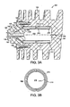
- FIG. 3 illustrates part of a rotor 200 of a screw pump.
- the tube 108 of the first embodiment is replaced by a tube 208, formed from similar material to the tube 108 and which similarly forms an interference fit with the cylindrical wall 112 of the cavity 106.
- This tube 208 also has an inner surface 214 that defines a bore 216 extending into the cavity 106 substantially co-axial with the body 102.
- the tube 208 differs from the tube 108 in that the slots 219 extending along the length of the tube 208 are located wholly within the tube 208, that is, between the inner 214 and outer 210 surfaces of the tube 208. Where the tube 208 is a single piece, these slots 219 may be formed by machining, during extrusion of the tube 208 or by any other suitable technique.
- the tube 208 may be formed in two parts, that is, an inner and an outer part, with the axially extending slots 219 being defined between the outer surface of the inner part and the inner surface of the outer part.
- the axially extending slots 219 being defined between the outer surface of the inner part and the inner surface of the outer part.
- grooves can be machined on the outer surface of the inner part (similar to the embodiment of the present invention shown in figure 2 ), with the outer part being in the form of a sleeve located over the inner part to close the grooves and form the slots 219.
- the rotor of figure 3 provides improved cooling as the outer surface 210 of the tube 208 is fully in contact with the wall 112 of the cavity 106; in the embodiment of the present invention, part of the outer surface 110 of the tube 108 is machined to form grooves 118 so that there is less surface area in direct contact with the body 102 to conduct heat from the body 102.
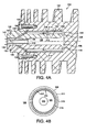
- Figure 4 illustrates part of a further rotor 300 of a screw pump.
- the end 126 of the shaft 120 has been extended in comparison to the embodiment so that, when the shaft 120 is attached to the body 102, a narrow radial clearance 348 is defined between the end 126 of the shaft 120 and the end wall 146 of the cavity 106.
- the longitudinal bore 128 is similarly extended in comparison to the embodiment so that the longitudinal bore 128 extends from the reduced diameter portion 130 to the end 126 of the shaft 120.
- the tube 308 of the rotor in figure 4 is located over the cylindrical wall 124 of the end 126 of the shaft 120, and again forms an interference fit with the cylindrical wall 112 of the cavity 106.
- the inner surface 314 of the tube 308 is machined, for example, using wire erosion, to form grooves 318 which, when the tube 308 is fitted over the end 126 of shaft 120, define with the wall 124 of the shaft 120 axially extending slots 319.
- slots 319 may be formed using an extrusion technique.
- Both the tube 308 and the shaft 120 define the guide for guiding the flow of coolant within the cavity 106.
- the stream of coolant received by and flowing through the bore 142 of the coolant supply tube 132 enters the longitudinal bore 128 from the end 134 of the coolant supply tube 132.
- the coolant flows through the bore 128 of the shaft 120, flows radially outwards between the end 126 of the shaft 120 and the end wall 146 of the cavity 106, and then enters the slots 319 defined between the tube 308 and the shaft 120.
- the coolant flows through the slots 319 in a direction opposite to the direction of the coolant flow through the bore 128 into the annular recess 138.
- the passage of the coolant from the annular recess 138 then follows the same path as that of the coolant from the annular recess 138 of the first embodiment.
- the arrangement can provide similar improvements in the cooling of the rotor 300 as the previously described configurations.
- the rotor 100, 200, 300 of any of the configurations may form part of a double-ended screw pump, as described in our earlier International patent application no. WO 2004/036049 .
- gas enters the pump at a centrally located inlet and forms two streams that are conveyed through the pump in opposite directions towards respective outlets provided at the ends of the rotors.
- the cooling arrangement shown in any of Figures 2 to 4 may be provided at each end of the rotor.
Landscapes
- Engineering & Computer Science (AREA)
- Mechanical Engineering (AREA)
- General Engineering & Computer Science (AREA)
- Applications Or Details Of Rotary Compressors (AREA)
Claims (17)
- Rotor (100 ; 200 ; 300) pour une pompe à vide, le rotor comprenant un corps fileté (102), une cavité (106) s'étendant axialement dans le corps, des moyens (132) pour alimenter la cavité avec un réfrigérant, des moyens (128) pour évacuer le réfrigérant de la cavité, et des moyens situés dans la cavité pour guider un flux du réfrigérant entre les moyens d'alimentation et les moyens d'évacuation, dans lequel les moyens de guidage comprennent un tube (108 ; 208 ; 308) ayant une surface intérieure (114 ; 214 ; 314) définissant un alésage (116 ; 216 ; 128) et une surface extérieure (110 ; 210 ; 310), caractérisé en ce que ladite surface extérieure (110 ; 210 ; 310) est fixe par rapport au corps et en contact avec lui pour permettre à la chaleur de lui être transférée par le corps, et définit au moins en partie une pluralité de fentes (119; 219; 319) s'étendant le long du tube, les fentes étant espacées radialement de l'alésage (116 ; 216 ; 128) et en communication fluidique avec lui de telle sorte que l'alésage (116 ; 216 ; 128) et les fentes guident le réfrigérant entre les moyens d'alimentation et les moyens d'évacuation.
- Rotor selon la revendication 1, dans lequel les moyens de guidage (108 ; 208 ; 308) sont formés dans un matériau différent de celui du corps fileté (102).
- Rotor selon la revendication 1 ou 2, dans lequel une partie au moins des moyens de guidage (108 ; 208 ; 308) sont formés dans un matériau ayant une conductivité thermique qui est égale ou supérieure à celle du matériau dans lequel est formé le corps fileté (102).
- Rotor selon l'une quelconque des revendications précédentes, dans lequel lesdits une partie au moins des moyens de guidage (108 ; 208 ; 308) sont formés dans un matériau métallique.
- Rotor selon l'une quelconque des revendications précédentes, dans lequel lesdits une partie au moins des moyens de guidage (108 ; 208 ; 308) sont formés dans de l'aluminium, du cuivre, du fer, ou tout alliage de ceux-ci.
- Rotor selon l'une quelconque des revendications précédentes, dans lequel le tube (108 ; 208 ; 308) possède une section transversale circulaire.
- Rotor selon l'une quelconque des revendications précédentes, dans lequel les moyens de guidage comprennent un arbre (120) autour duquel ledit tube (308) est situé.
- Rotor selon l'une quelconque des revendications précédentes, dans lequel les moyens d'alimentation comprennent un tube d'alimentation (132) pour fournir le réfrigérant aux moyens de guidage (108 ; 208 ; 308).
- Rotor selon la revendication 8, dans lequel le tube d'alimentation (132) est prévu pour fournir le réfrigérant à l'alésage (116 ; 216 ; 128) des moyens de guidage (108 ; 208 ; 308).
- Rotor selon la revendication 9, dans lequel le tube d'alimentation (132) est sensiblement coaxial avec le corps (102).
- Rotor selon l'une quelconque des revendications 8 à 10, dans lequel le tube d'alimentation (132) est situé à l'intérieur d'un arbre (120) fixé au corps (102).
- Rotor selon la revendication 11, dans lequel un palier (130) est situé entre le tube d'alimentation (132) et l'arbre (120) pour empêcher la rotation du tube d'alimentation avec l'arbre.
- Rotor selon la revendication 11 ou 12, dans lequel les moyens de décharge comprennent une conduite d'évacuation (128) située à l'intérieur de l'arbre (120).
- Rotor selon la revendication 13, dans lequel la conduite d'évacuation (128) s'étend autour du tube d'alimentation (132) et est sensiblement coaxiale avec lui.
- Rotor selon la revendication 13 ou 14, dans lequel les moyens de décharge comprennent des moyens (136) pour acheminer le réfrigérant des fentes (119 ; 219 ; 319) jusqu'à la conduite d'évacuation (128).
- Rotor selon la revendication 15, dans lequel les moyens d'acheminement comprennent une pluralité de secondes conduites d'évacuation (136) situées à l'intérieur de l'arbre (120) et allant chacune d'un canal annulaire (138) pour recevoir le réfrigérant desdites fentes (119; 219 ; 319) jusqu'à la première conduite d'évacuation mentionnée (128).
- Rotor (100 ; 200 ; 300) pour une pompe à vide, le rotor comprenant un corps fileté (102) ayant, à chaque extrémité de celui-ci, une cavité (106) s'étendant dans celui-ci, des moyens (132) pour alimenter chaque cavité avec un réfrigérant, et des moyens (128) pour évacuer le réfrigérant de chaque cavité, chaque cavité ayant, situés intérieurement, des moyens pour guider un flux du réfrigérant entre les moyens d'alimentation et les moyens d'évacuation, dans lequel les moyens de guidage comprennent un tube (108 ; 208 ; 308) ayant une surface intérieure (114 ; 214 ; 314) définissant un alésage (116 ; 216 ; 128) et une surface extérieure (110 ; 210 ; 310) caractérisé en ce que ladite surface extérieure (110 ; 210 ; 310) est fixe par rapport au corps et en contact avec lui pour permettre à la chaleur de lui être transférée par le corps, et définit au moins en partie une pluralité de fentes s'étendant le long du tube, les fentes (119; 219; 319) étant espacées radialement de l'alésage et en communication fluidique avec lui de telle sorte que l'alésage et les fentes guident le réfrigérant entre les moyens d'alimentation et les moyens d'évacuation.
Applications Claiming Priority (3)
| Application Number | Priority Date | Filing Date | Title |
|---|---|---|---|
| GB0419514A GB0419514D0 (en) | 2004-09-02 | 2004-09-02 | Cooling of pump rotors |
| GB0422195A GB0422195D0 (en) | 2004-10-06 | 2004-10-06 | Cooling of pump rotors |
| PCT/GB2005/003225 WO2006024818A1 (fr) | 2004-09-02 | 2005-08-17 | Refroidissement de rotors de pompe |
Publications (3)
| Publication Number | Publication Date |
|---|---|
| EP1784576A1 EP1784576A1 (fr) | 2007-05-16 |
| EP1784576B1 EP1784576B1 (fr) | 2013-03-13 |
| EP1784576B2 true EP1784576B2 (fr) | 2016-01-13 |
Family
ID=34979025
Family Applications (1)
| Application Number | Title | Priority Date | Filing Date |
|---|---|---|---|
| EP05772932.9A Expired - Lifetime EP1784576B2 (fr) | 2004-09-02 | 2005-08-17 | Refroidissement de rotors de pompe |
Country Status (5)
| Country | Link |
|---|---|
| US (1) | US7963744B2 (fr) |
| EP (1) | EP1784576B2 (fr) |
| JP (1) | JP4955558B2 (fr) |
| KR (1) | KR101129774B1 (fr) |
| WO (1) | WO2006024818A1 (fr) |
Families Citing this family (12)
| Publication number | Priority date | Publication date | Assignee | Title |
|---|---|---|---|---|
| DE19963172A1 (de) * | 1999-12-27 | 2001-06-28 | Leybold Vakuum Gmbh | Schraubenpumpe mit einem Kühlmittelkreislauf |
| BE1018583A3 (fr) * | 2009-06-10 | 2011-04-05 | Atlas Copco Airpower Nv | |
| DE102010061202A1 (de) * | 2010-12-14 | 2012-06-14 | Gebr. Becker Gmbh | Vakuumpumpe |
| EP2615307B1 (fr) * | 2012-01-12 | 2019-08-21 | Vacuubrand Gmbh + Co Kg | Pompe à vide à vis |
| CN105697373B (zh) * | 2014-11-25 | 2017-08-25 | 巫修海 | 一种螺杆真空泵的螺杆 |
| CN107690517B (zh) * | 2015-06-11 | 2020-06-09 | 伊顿智能动力有限公司 | 具有使用压入配合的短轴的转子的增压器 |
| US9683569B2 (en) * | 2015-08-27 | 2017-06-20 | Ingersoll-Rand Company | Compressor system having rotor with distributed coolant conduits and method |
| US10495090B2 (en) | 2015-08-27 | 2019-12-03 | Ingersoll-Rand Company | Rotor for a compressor system having internal coolant manifold |
| KR101712962B1 (ko) | 2015-09-24 | 2017-03-07 | 이인철 | 냉각장치를 갖춘 진공펌프 |
| JP6982380B2 (ja) | 2016-03-08 | 2021-12-17 | コベルコ・コンプレッサ株式会社 | スクリュ圧縮機 |
| US11268512B2 (en) * | 2017-01-11 | 2022-03-08 | Carrier Corporation | Fluid machine with helically lobed rotors |
| JP7811460B2 (ja) * | 2021-11-09 | 2026-02-05 | 株式会社日立産機システム | スクリュー圧縮機 |
Citations (12)
| Publication number | Priority date | Publication date | Assignee | Title |
|---|---|---|---|---|
| GB464493A (en) † | 1934-10-16 | 1937-04-16 | Milo Ab | Improvements in rotary engines |
| GB467022A (en) † | 1935-12-09 | 1937-06-09 | Thomas Winter Nichols | Improvements in rotary compressors, exhausters, pumps and the like |
| US2873909A (en) † | 1954-10-26 | 1959-02-17 | Svenska Rotor Maskiner Ab | Rotary devices and casing structures therefor |
| FR1290239A (fr) † | 1961-02-28 | 1962-04-13 | Alsacienne Constr Meca | Pompe à vide |
| DE2110940A1 (de) † | 1970-03-11 | 1971-10-07 | Ewitsch Amosow Pawel Ewgen | Schraubenrad fuer Drehkolbenmaschinen |
| JPS49118104A (fr) † | 1973-03-17 | 1974-11-12 | ||
| JPS5131911A (ja) † | 1974-09-13 | 1976-03-18 | Hitachi Ltd | Reikyakuyochukubuosonaetakaitentai |
| DE19745616A1 (de) † | 1997-10-10 | 1999-04-15 | Leybold Vakuum Gmbh | Gekühlte Schraubenvakuumpumpe |
| DE19820523A1 (de) † | 1998-05-08 | 1999-11-11 | Peter Frieden | Schraubenspindel-Vakuumpumpe mit Rotorkühlung |
| US6045343A (en) † | 1998-01-15 | 2000-04-04 | Sunny King Machinery Co., Ltd. | Internally cooling rotary compression equipment |
| DE19963171A1 (de) † | 1999-12-27 | 2001-06-28 | Leybold Vakuum Gmbh | Gekühlte Schraubenvakuumpumpe |
| WO2004036049A1 (fr) † | 2002-10-14 | 2004-04-29 | The Boc Group Plc | Pompe a vis |
Family Cites Families (9)
| Publication number | Priority date | Publication date | Assignee | Title |
|---|---|---|---|---|
| FR1360938A (fr) | 1963-06-18 | 1964-05-15 | Perfectionnements apportés au mode de montage des palettes et de leurs dispositifs d'étanchéité dans des compresseurs rotatifs à palettes | |
| JPS49118104U (fr) * | 1973-02-05 | 1974-10-09 | ||
| JPS5143915U (fr) * | 1974-09-30 | 1976-03-31 | ||
| WO1995002767A1 (fr) | 1993-07-13 | 1995-01-26 | Thomassen International B.V. | Compresseur rotatif a vis |
| JP3965507B2 (ja) * | 1995-06-21 | 2007-08-29 | ステアリング・インダストリー・コンサルト・ゲゼルシャフト・ミット・ベシュレンクテル・ハフツング | 多段スクリュースピンドル圧縮機 |
| DE19745615A1 (de) * | 1997-10-10 | 1999-04-15 | Leybold Vakuum Gmbh | Schraubenvakuumpumpe mit Rotoren |
| DE19817351A1 (de) * | 1998-04-18 | 1999-10-21 | Peter Frieden | Schraubenspindel-Vakuumpumpe mit Gaskühlung |
| DE19963172A1 (de) * | 1999-12-27 | 2001-06-28 | Leybold Vakuum Gmbh | Schraubenpumpe mit einem Kühlmittelkreislauf |
| DE10039006A1 (de) * | 2000-08-10 | 2002-02-21 | Leybold Vakuum Gmbh | Zweiwellenvakuumpumpe |
-
2005
- 2005-08-17 EP EP05772932.9A patent/EP1784576B2/fr not_active Expired - Lifetime
- 2005-08-17 KR KR1020077004961A patent/KR101129774B1/ko not_active Expired - Lifetime
- 2005-08-17 US US11/661,490 patent/US7963744B2/en active Active
- 2005-08-17 WO PCT/GB2005/003225 patent/WO2006024818A1/fr not_active Ceased
- 2005-08-17 JP JP2007528956A patent/JP4955558B2/ja not_active Expired - Lifetime
Patent Citations (12)
| Publication number | Priority date | Publication date | Assignee | Title |
|---|---|---|---|---|
| GB464493A (en) † | 1934-10-16 | 1937-04-16 | Milo Ab | Improvements in rotary engines |
| GB467022A (en) † | 1935-12-09 | 1937-06-09 | Thomas Winter Nichols | Improvements in rotary compressors, exhausters, pumps and the like |
| US2873909A (en) † | 1954-10-26 | 1959-02-17 | Svenska Rotor Maskiner Ab | Rotary devices and casing structures therefor |
| FR1290239A (fr) † | 1961-02-28 | 1962-04-13 | Alsacienne Constr Meca | Pompe à vide |
| DE2110940A1 (de) † | 1970-03-11 | 1971-10-07 | Ewitsch Amosow Pawel Ewgen | Schraubenrad fuer Drehkolbenmaschinen |
| JPS49118104A (fr) † | 1973-03-17 | 1974-11-12 | ||
| JPS5131911A (ja) † | 1974-09-13 | 1976-03-18 | Hitachi Ltd | Reikyakuyochukubuosonaetakaitentai |
| DE19745616A1 (de) † | 1997-10-10 | 1999-04-15 | Leybold Vakuum Gmbh | Gekühlte Schraubenvakuumpumpe |
| US6045343A (en) † | 1998-01-15 | 2000-04-04 | Sunny King Machinery Co., Ltd. | Internally cooling rotary compression equipment |
| DE19820523A1 (de) † | 1998-05-08 | 1999-11-11 | Peter Frieden | Schraubenspindel-Vakuumpumpe mit Rotorkühlung |
| DE19963171A1 (de) † | 1999-12-27 | 2001-06-28 | Leybold Vakuum Gmbh | Gekühlte Schraubenvakuumpumpe |
| WO2004036049A1 (fr) † | 2002-10-14 | 2004-04-29 | The Boc Group Plc | Pompe a vis |
Also Published As
| Publication number | Publication date |
|---|---|
| KR20070048223A (ko) | 2007-05-08 |
| EP1784576B1 (fr) | 2013-03-13 |
| JP4955558B2 (ja) | 2012-06-20 |
| EP1784576A1 (fr) | 2007-05-16 |
| KR101129774B1 (ko) | 2012-03-23 |
| JP2008511788A (ja) | 2008-04-17 |
| WO2006024818A1 (fr) | 2006-03-09 |
| US20080031761A1 (en) | 2008-02-07 |
| US7963744B2 (en) | 2011-06-21 |
Similar Documents
| Publication | Publication Date | Title |
|---|---|---|
| EP1784576B2 (fr) | Refroidissement de rotors de pompe | |
| EP3135862B1 (fr) | Système de compresseur à rotor avec des conduites de réfrigérant distribuées et procédé | |
| EP1007853B1 (fr) | Appareil a rotor en forme de vis, fonctionnant sans huile | |
| NL1021656C2 (nl) | Compressoreenheid met gemeenschappelijke behuizing voor elektromotor en compressor, werkwijze voor het vervaardigen van een scheidingswand voor een compressoreenheid en gebruik van een compressoreenheid. | |
| EP3135863B1 (fr) | Rotor destiné à un système compresseur avec collecteur de refroidissement interne | |
| JP6069530B2 (ja) | ねじスピンドル式ポンプ | |
| CN100473838C (zh) | 泵转子的冷却 | |
| US12378961B2 (en) | Screw pump with a tapered suction-side section and a pressure-side section with a decreasing clearance | |
| SE501187C2 (sv) | Skruvrotormaskin | |
| WO2006061558A1 (fr) | Pompe a vide a dissipateur thermique sur arbre rotor | |
| CN103261694B (zh) | 真空泵 | |
| KR100811360B1 (ko) | 직접냉각 2단 연속압축 스크류식 진공펌프 | |
| US5887473A (en) | Continuous extrusion apparatus | |
| KR102926660B1 (ko) | 개선된 오일 인젝터를 갖는 압축기 요소 | |
| US20190360485A1 (en) | Screw spindle pump | |
| EP1748192B1 (fr) | Chemise de cylindre céramique avec fente | |
| CN116583678A (zh) | 具有通过流过机器的介质进行的冷却和润滑的径向流体机器 | |
| US6530762B2 (en) | Vacuum pump cooling system, and a method of making it | |
| JP7811460B2 (ja) | スクリュー圧縮機 | |
| CN112012931A (zh) | 一种泵转子的冷却设计 | |
| US20190211819A1 (en) | External gear pump for a waste heat recovery system | |
| GB2421054A (en) | Vacuum pump with cooled shaft seal surface and bearing | |
| EP4057484B1 (fr) | Compresseur doté d'une gaine de refroidissement de moteur électrique ayant des parties radiales et axiales | |
| CN121474118A (zh) | 具有多组内轴齿轮的齿轮泵 |
Legal Events
| Date | Code | Title | Description |
|---|---|---|---|
| PUAI | Public reference made under article 153(3) epc to a published international application that has entered the european phase |
Free format text: ORIGINAL CODE: 0009012 |
|
| 17P | Request for examination filed |
Effective date: 20070207 |
|
| AK | Designated contracting states |
Kind code of ref document: A1 Designated state(s): AT BE BG CH CY CZ DE DK EE ES FI FR GB GR HU IE IS IT LI LT LU LV MC NL PL PT RO SE SI SK TR |
|
| RAP1 | Party data changed (applicant data changed or rights of an application transferred) |
Owner name: EDWARDS LIMITED |
|
| DAX | Request for extension of the european patent (deleted) | ||
| 17Q | First examination report despatched |
Effective date: 20110615 |
|
| GRAP | Despatch of communication of intention to grant a patent |
Free format text: ORIGINAL CODE: EPIDOSNIGR1 |
|
| GRAS | Grant fee paid |
Free format text: ORIGINAL CODE: EPIDOSNIGR3 |
|
| GRAA | (expected) grant |
Free format text: ORIGINAL CODE: 0009210 |
|
| AK | Designated contracting states |
Kind code of ref document: B1 Designated state(s): AT BE BG CH CY CZ DE DK EE ES FI FR GB GR HU IE IS IT LI LT LU LV MC NL PL PT RO SE SI SK TR |
|
| REG | Reference to a national code |
Ref country code: GB Ref legal event code: FG4D Ref country code: DE Ref legal event code: R081 Ref document number: 602005038577 Country of ref document: DE Owner name: EDWARDS LTD., BURGESS HILL, GB Free format text: FORMER OWNER: THE BOC GROUP PLC, WINDLESHAM, SURREY, GB |
|
| REG | Reference to a national code |
Ref country code: CH Ref legal event code: EP Ref country code: AT Ref legal event code: REF Ref document number: 600962 Country of ref document: AT Kind code of ref document: T Effective date: 20130315 |
|
| REG | Reference to a national code |
Ref country code: IE Ref legal event code: FG4D |
|
| REG | Reference to a national code |
Ref country code: DE Ref legal event code: R082 Ref document number: 602005038577 Country of ref document: DE Representative=s name: FLEUCHAUS & GALLO PARTNERSCHAFT MBB, DE Ref country code: DE Ref legal event code: R082 Ref document number: 602005038577 Country of ref document: DE Representative=s name: FLEUCHAUS & GALLO PARTNERSCHAFT, DE |
|
| REG | Reference to a national code |
Ref country code: DE Ref legal event code: R096 Ref document number: 602005038577 Country of ref document: DE Effective date: 20130508 |
|
| PG25 | Lapsed in a contracting state [announced via postgrant information from national office to epo] |
Ref country code: BG Free format text: LAPSE BECAUSE OF FAILURE TO SUBMIT A TRANSLATION OF THE DESCRIPTION OR TO PAY THE FEE WITHIN THE PRESCRIBED TIME-LIMIT Effective date: 20130613 Ref country code: ES Free format text: LAPSE BECAUSE OF FAILURE TO SUBMIT A TRANSLATION OF THE DESCRIPTION OR TO PAY THE FEE WITHIN THE PRESCRIBED TIME-LIMIT Effective date: 20130624 Ref country code: LT Free format text: LAPSE BECAUSE OF FAILURE TO SUBMIT A TRANSLATION OF THE DESCRIPTION OR TO PAY THE FEE WITHIN THE PRESCRIBED TIME-LIMIT Effective date: 20130313 Ref country code: SE Free format text: LAPSE BECAUSE OF FAILURE TO SUBMIT A TRANSLATION OF THE DESCRIPTION OR TO PAY THE FEE WITHIN THE PRESCRIBED TIME-LIMIT Effective date: 20130313 |
|
| REG | Reference to a national code |
Ref country code: AT Ref legal event code: MK05 Ref document number: 600962 Country of ref document: AT Kind code of ref document: T Effective date: 20130313 |
|
| REG | Reference to a national code |
Ref country code: NL Ref legal event code: VDEP Effective date: 20130313 |
|
| REG | Reference to a national code |
Ref country code: LT Ref legal event code: MG4D |
|
| PG25 | Lapsed in a contracting state [announced via postgrant information from national office to epo] |
Ref country code: LV Free format text: LAPSE BECAUSE OF FAILURE TO SUBMIT A TRANSLATION OF THE DESCRIPTION OR TO PAY THE FEE WITHIN THE PRESCRIBED TIME-LIMIT Effective date: 20130313 Ref country code: GR Free format text: LAPSE BECAUSE OF FAILURE TO SUBMIT A TRANSLATION OF THE DESCRIPTION OR TO PAY THE FEE WITHIN THE PRESCRIBED TIME-LIMIT Effective date: 20130614 Ref country code: FI Free format text: LAPSE BECAUSE OF FAILURE TO SUBMIT A TRANSLATION OF THE DESCRIPTION OR TO PAY THE FEE WITHIN THE PRESCRIBED TIME-LIMIT Effective date: 20130313 Ref country code: SI Free format text: LAPSE BECAUSE OF FAILURE TO SUBMIT A TRANSLATION OF THE DESCRIPTION OR TO PAY THE FEE WITHIN THE PRESCRIBED TIME-LIMIT Effective date: 20130313 |
|
| PG25 | Lapsed in a contracting state [announced via postgrant information from national office to epo] |
Ref country code: BE Free format text: LAPSE BECAUSE OF FAILURE TO SUBMIT A TRANSLATION OF THE DESCRIPTION OR TO PAY THE FEE WITHIN THE PRESCRIBED TIME-LIMIT Effective date: 20130313 |
|
| PG25 | Lapsed in a contracting state [announced via postgrant information from national office to epo] |
Ref country code: AT Free format text: LAPSE BECAUSE OF FAILURE TO SUBMIT A TRANSLATION OF THE DESCRIPTION OR TO PAY THE FEE WITHIN THE PRESCRIBED TIME-LIMIT Effective date: 20130313 Ref country code: SK Free format text: LAPSE BECAUSE OF FAILURE TO SUBMIT A TRANSLATION OF THE DESCRIPTION OR TO PAY THE FEE WITHIN THE PRESCRIBED TIME-LIMIT Effective date: 20130313 Ref country code: EE Free format text: LAPSE BECAUSE OF FAILURE TO SUBMIT A TRANSLATION OF THE DESCRIPTION OR TO PAY THE FEE WITHIN THE PRESCRIBED TIME-LIMIT Effective date: 20130313 Ref country code: NL Free format text: LAPSE BECAUSE OF FAILURE TO SUBMIT A TRANSLATION OF THE DESCRIPTION OR TO PAY THE FEE WITHIN THE PRESCRIBED TIME-LIMIT Effective date: 20130313 Ref country code: PT Free format text: LAPSE BECAUSE OF FAILURE TO SUBMIT A TRANSLATION OF THE DESCRIPTION OR TO PAY THE FEE WITHIN THE PRESCRIBED TIME-LIMIT Effective date: 20130715 Ref country code: IS Free format text: LAPSE BECAUSE OF FAILURE TO SUBMIT A TRANSLATION OF THE DESCRIPTION OR TO PAY THE FEE WITHIN THE PRESCRIBED TIME-LIMIT Effective date: 20130713 Ref country code: RO Free format text: LAPSE BECAUSE OF FAILURE TO SUBMIT A TRANSLATION OF THE DESCRIPTION OR TO PAY THE FEE WITHIN THE PRESCRIBED TIME-LIMIT Effective date: 20130313 |
|
| PG25 | Lapsed in a contracting state [announced via postgrant information from national office to epo] |
Ref country code: PL Free format text: LAPSE BECAUSE OF FAILURE TO SUBMIT A TRANSLATION OF THE DESCRIPTION OR TO PAY THE FEE WITHIN THE PRESCRIBED TIME-LIMIT Effective date: 20130313 Ref country code: CY Free format text: LAPSE BECAUSE OF FAILURE TO SUBMIT A TRANSLATION OF THE DESCRIPTION OR TO PAY THE FEE WITHIN THE PRESCRIBED TIME-LIMIT Effective date: 20130313 |
|
| PLBI | Opposition filed |
Free format text: ORIGINAL CODE: 0009260 |
|
| 26 | Opposition filed |
Opponent name: OERLIKON LEYBOLD VACUUM GMBH Effective date: 20131130 |
|
| PLAX | Notice of opposition and request to file observation + time limit sent |
Free format text: ORIGINAL CODE: EPIDOSNOBS2 |
|
| PG25 | Lapsed in a contracting state [announced via postgrant information from national office to epo] |
Ref country code: DK Free format text: LAPSE BECAUSE OF FAILURE TO SUBMIT A TRANSLATION OF THE DESCRIPTION OR TO PAY THE FEE WITHIN THE PRESCRIBED TIME-LIMIT Effective date: 20130313 |
|
| REG | Reference to a national code |
Ref country code: DE Ref legal event code: R026 Ref document number: 602005038577 Country of ref document: DE Effective date: 20131130 |
|
| REG | Reference to a national code |
Ref country code: CH Ref legal event code: PL |
|
| PG25 | Lapsed in a contracting state [announced via postgrant information from national office to epo] |
Ref country code: LI Free format text: LAPSE BECAUSE OF NON-PAYMENT OF DUE FEES Effective date: 20130831 Ref country code: CH Free format text: LAPSE BECAUSE OF NON-PAYMENT OF DUE FEES Effective date: 20130831 Ref country code: MC Free format text: LAPSE BECAUSE OF FAILURE TO SUBMIT A TRANSLATION OF THE DESCRIPTION OR TO PAY THE FEE WITHIN THE PRESCRIBED TIME-LIMIT Effective date: 20130313 |
|
| PLAF | Information modified related to communication of a notice of opposition and request to file observations + time limit |
Free format text: ORIGINAL CODE: EPIDOSCOBS2 |
|
| REG | Reference to a national code |
Ref country code: IE Ref legal event code: MM4A |
|
| PLBB | Reply of patent proprietor to notice(s) of opposition received |
Free format text: ORIGINAL CODE: EPIDOSNOBS3 |
|
| PG25 | Lapsed in a contracting state [announced via postgrant information from national office to epo] |
Ref country code: IE Free format text: LAPSE BECAUSE OF NON-PAYMENT OF DUE FEES Effective date: 20130817 |
|
| PG25 | Lapsed in a contracting state [announced via postgrant information from national office to epo] |
Ref country code: TR Free format text: LAPSE BECAUSE OF FAILURE TO SUBMIT A TRANSLATION OF THE DESCRIPTION OR TO PAY THE FEE WITHIN THE PRESCRIBED TIME-LIMIT Effective date: 20130313 |
|
| PG25 | Lapsed in a contracting state [announced via postgrant information from national office to epo] |
Ref country code: HU Free format text: LAPSE BECAUSE OF FAILURE TO SUBMIT A TRANSLATION OF THE DESCRIPTION OR TO PAY THE FEE WITHIN THE PRESCRIBED TIME-LIMIT; INVALID AB INITIO Effective date: 20050817 Ref country code: LU Free format text: LAPSE BECAUSE OF NON-PAYMENT OF DUE FEES Effective date: 20130817 |
|
| REG | Reference to a national code |
Ref country code: FR Ref legal event code: PLFP Year of fee payment: 11 |
|
| PUAH | Patent maintained in amended form |
Free format text: ORIGINAL CODE: 0009272 |
|
| STAA | Information on the status of an ep patent application or granted ep patent |
Free format text: STATUS: PATENT MAINTAINED AS AMENDED |
|
| 27A | Patent maintained in amended form |
Effective date: 20160113 |
|
| AK | Designated contracting states |
Kind code of ref document: B2 Designated state(s): AT BE BG CH CY CZ DE DK EE ES FI FR GB GR HU IE IS IT LI LT LU LV MC NL PL PT RO SE SI SK TR |
|
| REG | Reference to a national code |
Ref country code: DE Ref legal event code: R102 Ref document number: 602005038577 Country of ref document: DE |
|
| REG | Reference to a national code |
Ref country code: FR Ref legal event code: PLFP Year of fee payment: 12 |
|
| REG | Reference to a national code |
Ref country code: FR Ref legal event code: PLFP Year of fee payment: 13 |
|
| REG | Reference to a national code |
Ref country code: DE Ref legal event code: R082 Ref document number: 602005038577 Country of ref document: DE Representative=s name: FLEUCHAUS & GALLO PARTNERSCHAFT MBB PATENTANWA, DE Ref country code: DE Ref legal event code: R082 Ref document number: 602005038577 Country of ref document: DE Representative=s name: FLEUCHAUS & GALLO PARTNERSCHAFT MBB, DE Ref country code: DE Ref legal event code: R081 Ref document number: 602005038577 Country of ref document: DE Owner name: EDWARDS LTD., BURGESS HILL, GB Free format text: FORMER OWNER: EDWARDS LTD., CRAWLEY, WEST SUSSEX, GB |
|
| REG | Reference to a national code |
Ref country code: FR Ref legal event code: PLFP Year of fee payment: 14 |
|
| REG | Reference to a national code |
Ref country code: FR Ref legal event code: CA Effective date: 20180906 |
|
| REG | Reference to a national code |
Ref country code: DE Ref legal event code: R082 Ref document number: 602005038577 Country of ref document: DE Representative=s name: FLEUCHAUS & GALLO PARTNERSCHAFT MBB - PATENT- , DE Ref country code: DE Ref legal event code: R082 Ref document number: 602005038577 Country of ref document: DE Representative=s name: FLEUCHAUS & GALLO PARTNERSCHAFT MBB PATENTANWA, DE |
|
| P01 | Opt-out of the competence of the unified patent court (upc) registered |
Effective date: 20230425 |
|
| PGFP | Annual fee paid to national office [announced via postgrant information from national office to epo] |
Ref country code: DE Payment date: 20240828 Year of fee payment: 20 |
|
| PGFP | Annual fee paid to national office [announced via postgrant information from national office to epo] |
Ref country code: GB Payment date: 20240827 Year of fee payment: 20 |
|
| PGFP | Annual fee paid to national office [announced via postgrant information from national office to epo] |
Ref country code: FR Payment date: 20240826 Year of fee payment: 20 |
|
| PGFP | Annual fee paid to national office [announced via postgrant information from national office to epo] |
Ref country code: CZ Payment date: 20240806 Year of fee payment: 20 |
|
| PGFP | Annual fee paid to national office [announced via postgrant information from national office to epo] |
Ref country code: IT Payment date: 20240822 Year of fee payment: 20 |
|
| REG | Reference to a national code |
Ref country code: DE Ref legal event code: R071 Ref document number: 602005038577 Country of ref document: DE |
|
| REG | Reference to a national code |
Ref country code: GB Ref legal event code: PE20 Expiry date: 20250816 |
|
| PG25 | Lapsed in a contracting state [announced via postgrant information from national office to epo] |
Ref country code: CZ Free format text: LAPSE BECAUSE OF EXPIRATION OF PROTECTION Effective date: 20250817 |