EP1784762B1 - System und verfahren zum richten einer optischen codeabtastvorrichtung - Google Patents
System und verfahren zum richten einer optischen codeabtastvorrichtung Download PDFInfo
- Publication number
- EP1784762B1 EP1784762B1 EP05787791A EP05787791A EP1784762B1 EP 1784762 B1 EP1784762 B1 EP 1784762B1 EP 05787791 A EP05787791 A EP 05787791A EP 05787791 A EP05787791 A EP 05787791A EP 1784762 B1 EP1784762 B1 EP 1784762B1
- Authority
- EP
- European Patent Office
- Prior art keywords
- image data
- location
- frame
- optical code
- aiming
- Prior art date
- Legal status (The legal status is an assumption and is not a legal conclusion. Google has not performed a legal analysis and makes no representation as to the accuracy of the status listed.)
- Expired - Lifetime
Links
Images



Classifications
-
- G—PHYSICS
- G06—COMPUTING OR CALCULATING; COUNTING
- G06K—GRAPHICAL DATA READING; PRESENTATION OF DATA; RECORD CARRIERS; HANDLING RECORD CARRIERS
- G06K7/00—Methods or arrangements for sensing record carriers, e.g. for reading patterns
- G06K7/10—Methods or arrangements for sensing record carriers, e.g. for reading patterns by electromagnetic radiation, e.g. optical sensing; by corpuscular radiation
- G06K7/14—Methods or arrangements for sensing record carriers, e.g. for reading patterns by electromagnetic radiation, e.g. optical sensing; by corpuscular radiation using light without selection of wavelength, e.g. sensing reflected white light
- G06K7/1404—Methods for optical code recognition
- G06K7/1439—Methods for optical code recognition including a method step for retrieval of the optical code
- G06K7/1443—Methods for optical code recognition including a method step for retrieval of the optical code locating of the code in an image
-
- G—PHYSICS
- G06—COMPUTING OR CALCULATING; COUNTING
- G06K—GRAPHICAL DATA READING; PRESENTATION OF DATA; RECORD CARRIERS; HANDLING RECORD CARRIERS
- G06K7/00—Methods or arrangements for sensing record carriers, e.g. for reading patterns
- G06K7/10—Methods or arrangements for sensing record carriers, e.g. for reading patterns by electromagnetic radiation, e.g. optical sensing; by corpuscular radiation
- G06K7/10544—Methods or arrangements for sensing record carriers, e.g. for reading patterns by electromagnetic radiation, e.g. optical sensing; by corpuscular radiation by scanning of the records by radiation in the optical part of the electromagnetic spectrum
- G06K7/10712—Fixed beam scanning
- G06K7/10722—Photodetector array or CCD scanning
-
- G—PHYSICS
- G06—COMPUTING OR CALCULATING; COUNTING
- G06K—GRAPHICAL DATA READING; PRESENTATION OF DATA; RECORD CARRIERS; HANDLING RECORD CARRIERS
- G06K7/00—Methods or arrangements for sensing record carriers, e.g. for reading patterns
- G06K7/10—Methods or arrangements for sensing record carriers, e.g. for reading patterns by electromagnetic radiation, e.g. optical sensing; by corpuscular radiation
- G06K7/10544—Methods or arrangements for sensing record carriers, e.g. for reading patterns by electromagnetic radiation, e.g. optical sensing; by corpuscular radiation by scanning of the records by radiation in the optical part of the electromagnetic spectrum
- G06K7/10792—Special measures in relation to the object to be scanned
- G06K7/10801—Multidistance reading
-
- G—PHYSICS
- G06—COMPUTING OR CALCULATING; COUNTING
- G06K—GRAPHICAL DATA READING; PRESENTATION OF DATA; RECORD CARRIERS; HANDLING RECORD CARRIERS
- G06K7/00—Methods or arrangements for sensing record carriers, e.g. for reading patterns
- G06K7/10—Methods or arrangements for sensing record carriers, e.g. for reading patterns by electromagnetic radiation, e.g. optical sensing; by corpuscular radiation
- G06K7/14—Methods or arrangements for sensing record carriers, e.g. for reading patterns by electromagnetic radiation, e.g. optical sensing; by corpuscular radiation using light without selection of wavelength, e.g. sensing reflected white light
-
- G—PHYSICS
- G06—COMPUTING OR CALCULATING; COUNTING
- G06K—GRAPHICAL DATA READING; PRESENTATION OF DATA; RECORD CARRIERS; HANDLING RECORD CARRIERS
- G06K2207/00—Other aspects
- G06K2207/1011—Aiming
Definitions
- This invention relates to optical code readers.
- this invention relates to a system and method for aiming an optical code scanning device at a selected optical code.
- Optical code scanner systems have been developed heretofore for reading optical codes such as bar code symbols appearing on a label or on a surface of an article.
- the symbol itself is a coded pattern of indicia comprised of, for example, a series of bars of various widths spaced apart from one another to bound spaces of various widths, where the bars and spaces having different light reflecting characteristics.
- the scanning devices in scanning systems electro-optically transform the graphic indicia into electrical signals, which are decoded into alphanumeric characters that are intended to be descriptive of the article or some characteristic thereof. Such characters are typically represented in digital form and utilized as an input to a data processing system for applications in point-of-sale processing, inventory control and the like.
- Optical code scanning devices are used in both fixed and portable installations in many diverse environments, such as in stores for check-out services, in manufacturing locations for work flow and inventory control, and in transport vehicles for tracking package handling.
- the scanning device can be used for rapid data entry, such as by scanning a target barcode from a printed listing of many barcodes.
- the optical code scanning device is connected to a portable data processing device or a data collection and transmission device.
- the optical code scanning device is a handheld scanning device including a handheld sensor which is manually directed at a target code.
- an individual scanning device is a component of a much larger system including other scanning devices, computers, cabling, data terminals, etc.
- Such systems are frequently designed and constructed on the basis of mechanical and optical specifications for the scanning engine, sometimes called "form factors".
- One such form factor is the SE1200 form factor designed by Symbol Technologies, Inc.
- One type of optical code scanning device is an array optical imager scanning device, which includes an image sensor having a one- or two-dimensional array of cells or photo sensors, such as an area charge coupled device (CCD).
- the imager scanning device images a target, including sensing light reflected off a target being imaged and generating a plurality of electrical signals corresponding to the sensing which correspond to a two-dimensional array of pixel information describing the field of view of the scanning device.
- the electrical signals are then processed and provided to decode circuitry for decoding thereof.
- the imager sensor includes associated circuitry for generating and processing the electrical signals.
- a lens assembly may be provided for focusing light incident on the image sensor.
- the scanning device When multiple optical codes are in the field of view (FOV) of the scanning device, the scanning device typically determines which optical code is the easiest to capture and/or read, and that optical code is decoded first. The user does not control which optical code the system should try to decode, and accordingly may have difficulty scanning a desired optical code.
- FOV field of view
- Scanning devices are often equipped with an aiming assembly which generates a visible aiming pattern, such as a "cross hair" pattern, which a user may train on a target object to be imaged in order to aim the scanning device at the target image.
- a visible aiming pattern such as a "cross hair" pattern
- the center of the aiming pattern it is common for the center of the aiming pattern to not coincide with the center of the field of view of the scanning device due to mechanical or manufacturing inconsistencies, including the displacement between a light source of the aiming assembly and a focal point of optics for focusing light onto the image sensor.
- the user may use the aiming pattern to scan a desired code that is presented together with multiple optical codes, such as on a page having one or more columns of optical codes.
- the user may try to align the center of the aiming pattern to coincide with or be nearest to the desired code and then activate a scanning operation, such as by pulling a trigger.
- the scanning device Upon activation of the scanning operation, the scanning device temporarily disables generation of the aiming pattern so that the aiming pattern is not incorporated into the image being acquired in order not to obstruct a target being imaged.
- the actual position of the aiming pattern in the acquired image is not necessarily in the center of the acquired image. In fact, the actual position of the aiming pattern is not known.
- the desired optical code is not necessarily the acquired optical code that is closest to the center of the acquired image. Accordingly, there is not a reliable way to determine which optical code of the multiple optical codes lying within the field of view of the scanning device is the desired optical code.
- a specific example of an optical code scanner with an imager module that acquires a series of image frame data is disclosed in WO 99/64980 A , wherein at least one frame is captured with an aiming pattern generated by an aiming assembly and another frame is captured without the aiming pattern being generated.
- an aiming controller must be present inherently.
- the pixel location of the aiming pattern center is determined from a captured frame that includes the aiming pattern.
- the scanner further includes an optical code selector for performing, in accordance with the determined location of the aiming pattern center, processing of a second frame of image data acquired without the aiming pattern and providing the one or more optical codes in a selected portion of the second frame for further processing, i.e., decoding.
- US-A-5,955,720 discloses a semi-retroreflective optical scanner system that has an optical scanning element which directs a scanning light beam via a stationary holographic optical element in a scan path across indicia to be read.
- US-A-6,060,722 discloses an optical assembly for use with electronic readers that has an imaging optical axis and which forms an image of a two-dimensional region on an opto-electronic imaging device.
- An aiming pattern generator includes at least a point like aiming light source and an interferometric pattern generating optical element that project onto the two-dimensional region a luminous aiming pattern that approximately coincides with the field of view of the imaging device.
- US-A-5,811,774 discloses an extended working range dataform reader with reduced power consumption and a circuit control board that includes gain control circuitry and exposure control circuitry configured to set an initial gain value and an initial exposure period, respectively, resulting from a previous dataform reading session.
- US-A-5,155,343 discloses a bar code reader that includes an optical system for storing two dimensional image in memory, which stored two dimensional image contains a bar code symbol.
- the bar code image is detected by computing the accumulated sum of the products of the derivatives of respective first and second scan lines as a location score for the image under consideration.
- the present disclosure advances the state of the art of optical code scanning by disclosing a system and method for aiming an optical code scanning device at a desired optical code of multiple optical codes in the field of view of the scanning device for decoding the desired optical code.
- an optical code scanner device system for reading at least one optical code, as set forth in claim 1.
- an optical code scanner system 10 for reading an optical code is shown, where the optical code scanner system 10 includes an imager scanning device 12 for reading an optical code, including imaging optical codes, where more than one optical code may be imaged at a time.
- the optical code may be for example, a barcode, a UPC/EAN, a one-dimensional or multidimensional code, a textual code, etc.
- "Read” or “Read operation” refers to imaging and decoding an optical code, but may further be understood as imaging and processing an optical code, such as for performing character recognition on the imaged optical code, transmitting or further processing the imaged optical code.
- the scanning device 12 includes an imager module 14, an actuator assembly 16, an aiming assembly 18, an aiming controller 20, and a processor assembly 22.
- the scanning device 12 may be in communication with one or more peripheral devices 24 such as a keyboard, display device, printer device, data storage medium, e.g., including storage for application software and/or databases, at least one remote processing device, e.g., a host processor, and/or another system or a network.
- peripheral devices 24 such as a keyboard, display device, printer device, data storage medium, e.g., including storage for application software and/or databases, at least one remote processing device, e.g., a host processor, and/or another system or a network.
- Executable on the processor assembly 20 are a decoder module 30, an optical code selector module 32, a parallax range module 34 and range finder module 36.
- the optical code selector module selects an optical code from one or more imaged optical codes and provides the selected optical code to the decoder module 30 for decoding thereof and/or for other further processing. Selection of the optical code is made in accordance with the location of the optical code relative to an aiming pattern generated by the aiming assembly 16, as described further below. It is envisioned that the scanning device 12 may operate in a variety of modes, where respective modes use a different method for selecting the optical code(s) to be decoded or otherwise further processed, and where one of the modes uses the method described in accordance with the present invention.
- the scanning device 12 may be configured as a handheld or portable device or as a stationary device such as provided in a fixed location, in a rotating turret. Furthermore, the scanning device 12 may be incorporated into a system, such as a local area, cellular or wide area network or a video phone system. Additionally, the scanning device 12 may further be incorporated into another device, such as a PDA or cellular phone.
- a coupling 26 is provided for connecting the scanning device 12 to the peripheral device 24.
- Coupling 26 may include wired or wireless couplings, such as a flexible electrical cable; a radio frequency, optical and/or cellular communication telephone exchange network, either through a modem or an ISDN interface; an infrared data interface (IRDA); a multi-contact shoe; or a docking device.
- Data transmitted by the coupling 26 may include compressed data.
- the peripheral device 24 preferably includes a host processor having at least one data processor, where the at least one data processor may be connected to one or more peripherals or computing devices, such as a video monitor, and/or a network. Analog and/or digital devices may be provided in the host processor and/or the scanning device 12 for processing signals corresponding to sensing of light reflected from a target being imaged or scanned by the scanning device 12.
- the decoder module 30 may be provided in the peripheral device 24, such as the host processor and/or in the scanning device 12.
- the imager module 14 constantly acquires an image corresponding to a field of view (FOV) of the imager module 14, and provides corresponding image data as a series of frames to the processor assembly 22.
- a photo sensor array (not shown) for sensing light reflected from objects lying within the field of view (FOV) of the scanning device 12, and generating an array of electrical signals representing an image which correspond to the sensing.
- Optics (not shown) may be provided for focusing the light onto the photo sensor array.
- the photo sensor array may include a CCD or other similar device, such as such as CMOS, a charge modulated device (CMD) or charge injection device (CID) sensors.
- the imager module 14 may further include circuitry, such as video circuitry, signal processing circuitry, etc., (not shown) for processing (e.g., filtering, buffering, amplifying, digitizing, etc.) the electrical signals for generating image data and interfacing with the processor assembly 22.
- the processed electrical signals are output periodically (synchronously or asynchronously) as a frame of image data including an array of pixels which correspond to the electrical signals.
- the imager module 14 outputs a series of frames of image data that correspond to the continual sensing by the photo sensor array.
- the series of frames are provided to the processor assembly 22, where the frames of image data may be immediately processed and/or stored in order to be available for future processing.
- the actuator assembly 16 includes an actuator, such as a trigger or switch (hardware or software), which may be activated by a user, a sensor, a processor, a host processor, etc., for generating an actuation signal upon activation thereof in order to initiate a read operation.
- the actuation signal may be generated by the host processor and received by the scanning device 12, such as in the form of a command.
- the aiming assembly 18 includes at least one light source, such as a laser light source and/or a non-laser light source, e.g., a LED, for generating at least one beam forming an aiming pattern, such as a crosshair, which is visibly projected in an area that corresponds to the field of view of the scanning device 12.
- the user may aim the scanning device 12 (which may include positioning the target optical code) so that the aiming pattern is situated to coincide with or be close to the target optical code to be imaged.
- the user aims the scanning device 12 at the target optical code, and then actuates the actuator assembly 16 for initiating a read operation. For example, once the user aims the imaging device by situating the aiming pattern to coincide with or be close to the target optical code.
- U.S. Patent No. 5,801,371 describes operation of a scanning device, including generation of an aiming pattern and aiming the scanning device using the aiming pattern, and is incorporated by reference herein in its entirety.
- the aiming controller 20 includes circuitry and/or software instructions executable on the processor assembly 22 and/or a data processor of the at least one peripheral device 24 for controlling enablement of the aiming assembly 18 for controlling generation of the aiming pattern during acquisition of at least one frame in response to receipt of the actuation signal.
- the circuitry may include digital, logic and/or analog devices.
- the aiming controller 20 may control the aiming assembly 18 so that a frame of image data that was captured while the user was aimed at the target optical code while the aiming pattern was visible is available, as well as a frame of image data that was captured while the user was aimed at the target optical code while the aiming pattern was not visible.
- the timing of controlling the aiming assembly 18 by the aiming controller 20 is discussed further below.
- the processor assembly 22 may include a microprocessor(s), a field programmable gate array (FPGA) and/or other processing device(s), and may further include at least one storage component, such as a flash memory device and/or a DRAM memory device. Further, the processor assembly 22 may communicate with the at least one peripheral device 24, such as the host processor. The processor assembly 22, or portions thereof, may alternatively be provided externally from the imager module 14, such as on another circuit board separate from that which the imager module 14 is provided on, and/or in the host processor. The processor assembly 22 receives the actuation signal when a read operation is initiated, and receives or retrieves respective frames of data of the series of frames upon receipt of the actuation signal for processing thereof.
- FPGA field programmable gate array
- the decoder module 30, the optical code selector module 32, the parallax range module 34 and at least portions of the aiming controller 20 and the range finder module 36, respectively, include a series of programmable instructions executable on the processor assembly 22 and or another processor external to the scanning device 12, such as the host processor.
- the series of programmable instructions can be stored on a computer-readable medium, such as RAM, a hard drive, CD, smart card, 3.5" diskette, etc., or transmitted via propagated signals for being executed by the processor assembly 22 for performing the functions disclosed herein and to achieve a technical effect in accordance with the invention.
- the processor assembly 22 is not limited to the software modules described. The functions of the respective software modules may be combined into one module or distributed among a different combination of modules.
- the decoder module 30 receives optical codes or portions thereof and performs a decode operation on the respective codes and outputs a corresponding decoded code. It is contemplated that when receiving a partial code, the decoder module 30 may retrieve another portion of the code as needed for decoding thereof.
- the decode operation may include decoding a barcode or other type of symbol, such as a text code including alphanumeric characters.
- the decoding process may include character recognition processing.
- the optical code selector module 32 in response to receipt of the actuation signal, processes at least a portion of at least a first and second frame of image data.
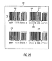
- Exemplary first and second frames 200 and 202 are shown in FIGS. 2A and 2B , respectively.
- the first frame of image data 200 is acquired while the aiming pattern 204 is generated and visible, so that the aiming pattern 204 was captured during acquisition of the first frame of image data.
- several optical codes 210 are acquired, but optical code 212 is the optical code that the user wants decoded.
- the pixel that corresponds to the center of the array of pixels associated with the FOV of the imaging device 14 is shown as point 208.
- the pixel 206a at the center of the aiming pattern 204 does not coincide with the pixel located at point 208.
- FIG. 2B shows a second frame of image data 202 acquired while the aiming pattern is not generated and is not visible.
- frames 200 and 202 are acquired in rapid sequence, preferably with frame 200 acquired immediately prior to frame 202, but not limited thereto.
- frames 200 and 202 may be acquired approximately 33msec apart from each other. Due to the rapid successive acquisitions of frames 200 and 202 as the user aims the scanning device 12, the FOV captured for frames 200 and 202 is substantially the same.
- the aiming pattern 204 was not captured during acquisition of the second frame of image data 202, but the location of the aiming pattern, specifically the center of the aiming pattern can be determined based on the location L of pixel 206a in the first frame 200.
- the pixel 206b of the array of pixels of frame 202 is determined which is located at location L, i.e., the location of pixel 206a as determined from the first frame 200.
- the target optical code 212 is selected from the other optical codes 210, where optical code 210 that is located nearest to pixel 206b.
- Optical code 212 is provided to the decoder module 30 for decoding thereof.
- optical codes, or portions thereof, that were found within a vicinity of (e.g., within a predetermined distance from) pixel 206b are further processed, such as for decoding thereof. Where a portion of an optical code lies within the vicinity of pixel 206b, the portion may be processed and/or remaining portions of the optical code may be processed, which may depend, for example, upon how significant a portion of the optical code was located within the vicinity.
- the scanning device 12 is in an aiming state, where the aiming pattern is generated and visible, so that the user may use the aiming pattern to aim the imager device so that the aiming pattern may be trained to coincide with a target optical code or be near the target optical code.
- a user of the scanning device 12 aims the scanning device 12 at the target optical code and activates the actuator assembly 16. As the actuator assembly 16 is activated the imager module 14 is acquiring a series of frames.
- the processor assembly 22 receives the actuation signal during acquisition of a frame N.
- image data of frame N+1 is acquired with the aiming pattern generated, so that the aiming pattern is acquired in the image data.
- at least a portion of the acquired image data of frame N+1 is processed by the optical code selector module 32 for determining the location L of the pixel 206a that corresponds to the center of the aiming pattern.
- the location L may be described by coordinates, e.g., (x,y).
- the generation of the aiming pattern is disabled.
- the image data of frame N+2 is acquired with the aiming pattern disabled (not generated), so that the aiming pattern is not acquired in the image data.
- at least a portion of the image data of frame N+2 is processed by the optical code selector module 32 for determining and selecting the optical code 212 located closest to a pixel 206b located at location L.
- optical codes are selected when the respective optical codes or a portion thereof, are found within a vicinity of (e.g., within a predetermined distance from) pixel 206b.
- the selected optical code(s) or portions thereof are processed, e.g., decoded by the decoder module 30.
- the processed, e.g., decoded, code is transmitted, such as to the at least one peripheral device 24, e.g., the host processor and/or a display device.
- step 302 occurs at frame N.
- step 304 is performed during acquisition of frame N+1.
- step 306 is performed during acquisition of frame N+1 and/or during acquisition of frame N+2.
- steps 308 and 312 are performed during acquisition of frame N+2, and step 314 is performed at the beginning of acquisition of frame N+3.
- Steps 306, 312 and/or 314 may be performed at substantially the same time that image data is being acquired. It is contemplated that one or more combination of the steps described maybe performed in parallel.
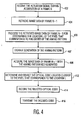
- the scanning device 12 is in an aiming state.
- the user aims the scanning device 12 at a target optical code and activates the actuator assembly 16.
- the processor assembly 22 receives the actuation signal during acquisition of a frame N.
- at least a portion of the image data of frame N-1 is retrieved from a storage medium where previously acquired frames of image data are stored.
- Frame N-1 is the frame which occurred prior to activation of the actuator assembly 16. Since frame N-1 occurred prior to activation of the actuator assembly 16, it is likely that the user was aimed at the target optical code and preparing to activate the actuator assembly 16.
- the aiming pattern was generated during acquisition of frame N-1, and accordingly the aiming pattern is acquired in the image data.
- at least a portion of the acquired image data of frame N-1 is processed by the optical code selector module 32 for determining the location L of the pixel 206a that corresponds to the center of the aiming pattern.
- the generation of the aiming pattern is disabled.
- the image data of frame N+1 is acquired with the aiming pattern disabled (not generated), so that the aiming pattern is not acquired in the image data.
- at least a portion of the image data of frame N+2 is processed by the optical code selector module 32 for determining and selecting the optical code 212 located closest to a pixel 206b located at location L. Alternatively, optical codes are selected when the respective optical codes or a portion thereof, are found within a vicinity of (e.g., within a predetermined distance from) pixel 206b.
- the selected optical code(s) or portions thereof are processed, e.g., decoded by the decoder module 30.
- the processed, e.g., decoded, code is transmitted, such as to the at least one peripheral device 24, e.g., the host processor and/or a display device.
- step 402 occurs during acquisition of frame N, and steps 404, 406 and 407 are performed during acquisition of frame N.
- steps 408 and 412 are performed during acquisition of frame N+1, and step 414 is performed at the beginning of acquisition of frame N+2.
- steps 406, 412 and/or 414 may be performed at substantially the same time that image data is being acquired. It is contemplated that one or more combination of the steps described may be performed in parallel.
- the image data acquired or processed includes a portion of image data corresponding to the particular frame, and that several iterations may be performed for acquiring and/or processing respective successive portions of image data corresponding to the particular frame and attempting to locate the location L, the target optical code 212 and/or perform a decode operation on the selected target optical code 212, until a condition is met, such as a successful completion of the step being performed, a sufficient number of processing attempts are performed on the particular frame, or a timeout condition occurs.
- Processing of the successive portions may be in accordance with availability of image data as it is acquired or the portions of the image data may be selected in accordance with design choice. Retrieval of image data acquired in a frame prior to activation of an actuator is described in US-B-7,097,102 .
- a dynamic calibration is performed upon respective activations of the actuation assembly 16 for properly determining the optical code that the scanning device 12 was aimed at.
- the dynamic calibration overcomes variations due to any tolerances or variances, such as those associated with manufacturing.
- the location L of the pixel associated with the center of the aiming pattern is stored for respective determinations of location L, e.g., for respective read operations.
- the optical code selector module retrieves at least one stored location L and calculates a location CL in accordance with at least one function of the retrieved at least one stored location L.
- the at least one function includes calculating an average of the respective retrieved at least one stored location L.
- Calculated location CL is calculated and updated as new determinations of location L are determined and stored. Storage of newly determined locations L and/or updating of the calculated location CL may be performed for each read operation or may be performed at regular or irregular intervals.
- the storage medium used for storing values for L and CL is nonvolatile and may be included with the processing assembly 22 or accessible by the processing assembly 22. It is further contemplated that the processing, and storing of L and CL may be performed by the host processor.
- the calculated location CL may be used in lieu of determining L, such as for a read operation in which the aiming pattern was generated during image acquisition, but the optical code selector module 32 determines that the position of the aiming pattern cannot be recovered in the processing of the acquired image data, e.g., the optical code selector module 32 doesn't succeed in sufficiently finding or processing the aiming pattern while processing the acquired image data This may occur when the aiming pattern is not detectable within the image data or was not sufficiently acquired.
- An exemplary situation in which the aiming pattern may not be detectable or sufficiently acquired is when the read operation is performed in bright ambient light conditions.
- the calculated location CL is used for selecting the optical code that is being aimed at.
- a method for determining whether the calculated location CL has been established or not is described further below. If it is determined that the calculated location CL has not been established, then L must be determined, such as by using the method in accordance with FIG. 3 or FIG. 4 .
- a read operation is performed by immediately disabling generation of the aiming pattern by the aiming controller 20 in response to receipt of the actuation signal.
- a first frame of image data is acquired with the aiming pattern disabled.
- the optical code selector module 32 processes the image data using the calculated location CL as the center of the aiming pattern in lieu of determining the location of the pixel that corresponds to the center of the aiming pattern and selects the optical code(s) that are located at a respective location, where the respective location relative to the calculated location CL meets a predetermined condition.
- the selected data may be transmitted for further processing, e.g., decoding, or the calculated location CL may be verified as follows.
- generation of the aiming pattern is enabled by the aiming controller 20, and a second frame of image data is acquired with the aiming pattern generated so that the aiming pattern is acquired with the second frame of image data.
- the second frame of image data is processed by the optical code selector module 32 for determining the location L of the pixel that corresponds to the center of the aiming pattern.
- the image data of the second frame is processed for selecting and processing the optical code that is located at a respective location, where the respective location relative to the determined location L meets a predetermined condition.
- determination of whether CL is established or not may be performed during previous read operations, such as by comparing a recently determined value for CL or L with a previously determined value for CL or L. CL may be determined to be established if the difference between the compared values is less than a predetermined threshold value.
- a parallax range module 34 which processes previously determined values for L, including tracking changes in L attributed to factors such as parallax, where the position of the aiming pattern depends on the distance between the target being imaged and the scanner system 10, and more particularly the scanning device 12.
- a range of possible values for L is established. Outside values for the range of possible L values correspond to outside values for a range of operational distances, where an operational distance is a distance between the scanning system, and more particularly the scanning device 12 (e.g., the photo sensor array thereof) and the target at which a successful read operation is attainable.
- the outside values for the range of operational distances are established the outside values for the range of possible L values may be determined either empirically and/or by calculations, as described below.
- the outside values for the range of operational distances may be established.
- the outside values for the range of operational distances may be established empirically where only operational distances associated with successful read operations are used for determining outside values thereof.
- the outside values for the range of operational distances for the scanning device 12 may be known for the particular model being used, or may be calculated based on specifications and geometries of the scanner system 10, and more particularly the scanning device 12.
- outside values of the range of possible values ofL may be established.
- maximum and minimum values of historical values of L based on normal use of the scanning device 12 maybe determined.
- the scanning device 12 may be operated by a user to test the outside limits of the scanning device 12, such as by scanning targets that are located at minimum and maximum operational distances from the scanning device 12 and storing the corresponding values of L.
- the historical values for L may include only values of L that were determined in association with a successful read operation.
- outside values for the range of possible values of L may also (or alternatively) be established based on calculations, which may include using knowledge about the specifications and geometries of the scanner system, and more particularly the scanning device 12.
- a frame of image data is acquired without the aiming pattern being generated so that the aiming pattern is not captured with the image data.
- Pixels associated with the range of possible values of L are located and established as a cluster of center pixels corresponding to the range of possible values of L.
- a neighborhood of pixels located within a pre-established threshold distance from.the cluster of center pixels are processed for finding optical codes.
- Optical codes, or portions thereof, that were found within the neighborhood of pixels are further processed, such as for decoding thereof. Where a portion of an optical code lies within the neighborhood of pixels, the portion may be processed and/or remaining portions of the optical code may be processed, which may depend upon how significant a portion of the optical code was located within the neighborhood of pixels.
- the system 10 further includes range finder module 36 including circuitry and/or executable instructions for determining the distance between the scanning device 12, e.g., the photo sensor array of the scanning device 12, and the target being imaged.
- range finder module 36 including circuitry and/or executable instructions for determining the distance between the scanning device 12, e.g., the photo sensor array of the scanning device 12, and the target being imaged.
- a frame of image data is acquired without the aiming pattern being generated so that the aiming pattern is not captured with the image data.
- the parallax range module 34 calculates the position L of the center of the aiming pattern using the distance determined by the range finder module 36 and the specific geometry of the scanning device 12, e.g., the geometry of the imager module 14.
- Optical codes, or portions thereof, that were found within a vicinity of (e.g., within a predetermined distance from) the pixel that corresponds to the calculated position L are further processed, such as for decoding thereof. Where a portion of an optical code lies within the vicinity of the pixel corresponding to position L, the portion may be processed and/or remaining portions of the optical code may be processed, which may depend upon how significant a portion of the optical code was located within the vicinity.
Landscapes
- Physics & Mathematics (AREA)
- Engineering & Computer Science (AREA)
- Electromagnetism (AREA)
- Health & Medical Sciences (AREA)
- General Health & Medical Sciences (AREA)
- Toxicology (AREA)
- Artificial Intelligence (AREA)
- Computer Vision & Pattern Recognition (AREA)
- General Physics & Mathematics (AREA)
- Theoretical Computer Science (AREA)
- Image Input (AREA)
- Facsimile Scanning Arrangements (AREA)
Claims (13)
- Ein optisches Codescannersystem (10) zum Lesen von zumindest einem optischen Code (210), das Folgendes aufweist:ein Abbildungsmodul (14), das angeordnet ist, um eine Reihe von Rahmen von Bilddaten zu erfassen, wobei die Bilddaten von den entsprechenden Rahmen eine Anordnung von Pixeldaten umfassen, die der Abbildung eines Sichtfelds des Abbildungsmoduls (14) entsprechen;eine Zielanordnung (18) mit zumindest einer Lichtquelle, die konfiguriert ist,um zumindest einen Strahl zu bilden, der ein Zielmuster (204) bildet, welches in dem Sichtfeld sichtbar ist;eine Zielsteuervorrichtung (20), die konfiguriert ist, um die Zielanordnung (18) zu steuern, wodurch die Erzeugung des Zielmusters (204) während des Abbildens gesteuert wird; undein optisches Codeauswahlmodul (32), das auf zumindest einem Prozessor (22) ausführbar ist, welches konfiguriert ist, um zumindest einen Teil von zumindest einem Rahmen der Bilddaten zu verarbeiten, der vor dem Empfang eines Betätigungssignals, welches eine Anzeige für die Initiierung eines Lesebetriebs bildet, und während das Zielmuster erzeugt wurde, um eine Position (L) von zumindest einem Pixel der Anordnung von Pixeldaten zu bestimmen, die mit dem Zielmuster (204) übereinstimmen, erfasst wurde,und welches konfiguriert ist, um zumindest einen Teil eines ersten Rahmens der Bilddaten zu verarbeiten, der nach dem Empfang des Betätigungssignals und während die Erzeugung des Zielmusters abgeschaltet war erfasst wurden und für die das Sichtfeld im Wesentlichen das gleiche wie für den zumindest einen Rahmen ist, der vor dem Empfang des Betätigungssignals erfasst wurde, und zwar einschließlich der Auswahl von zumindest einem optischen Code (210), der in dem zumindest einen Teil des ersten Rahmens der Bilddaten erfasst wurde, der an einer entsprechenden Stelle gelegen ist, wobei die entsprechende Stelle eine vorbestimmte Beziehung zu der bestimmten Stelle erfüllt, und das konfiguriert ist, um den ausgewählten zumindest einen optischen Code (210) zur weiteren Verarbeitung gemäß dem Lesevorgang vorzusehen,wobei die bestimmte Position vor dem Empfang des Betätigungssignals gespeichert wird und Daten bezüglich der gespeicherten, bestimmten Position nach dem Empfang des Betätigungssignals abgefragt werden,wobei das System dadurch gekennzeichnet ist, dass:die Zielsteuervorrichtung (20) konfiguriert ist, um die Zielanordnung (18) zu steuern, um das Zielmuster (204) zu erzeugen, wenn ein zweiter Rahmen der Bilddaten nach dem Empfang des Betätigungssignals erfasst wird,das optische Codeauswahlmodul (32) konfiguriert ist, um zumindest einen Teil des zweiten Rahmens der Bilddaten zu verarbeiten, um eine Position von zumindest einem Pixel der Anordnung von Pixeldaten zu bestimmen, die mit dem Zielmuster (204) übereinstimmen, welches in dem zweiten Rahmen der Bilddaten erfasst wird.,das optische Codeauswahlmodul (32) konfiguriert ist, um die Position, die für den zweiten Rahmen der Bilddaten bestimmt wurde, mit den abgefragten Daten in Bezug auf die bestimmte Position zu vergleichen; unddas optische Codeauswahlmodul (32) konfiguriert ist, um die abgefragten Daten in Bezug auf die bestimmte Position zur Auswahl des zumindest einen optischen Codes zu verwenden, wenn die Differenz zwischen den verglichenen Werten unterhalb eines Schwellenwerts liegt; unddas optische Codeauswahlmodul (32) konfiguriert ist, um andernfalls die Position zu verwenden, die für den zweiten Rahmen der Bilddaten bestimmt wurde, um den zumindest einen optischen Code (210) auszuwählen.
- System gemäß Anspruch 1, wobei der zumindest eine Teil des ersten Rahmens der Bilddaten ansprechend auf den Empfang des Betätigungssignals verarbeitet wird.
- System gemäß Anspruch 1, wobei der Prozessor (22) konfiguriert ist, um einen ersten (200) und einen zweiten (202) Rahmen der Bilddaten der Reihe von Rahmen von Bilddaten zu verarbeiten, um eine erste und eine zweite Position von zumindest einem Pixel zu bestimmen, das mit dem Zielmuster (204) übereinstimmt, das in den ersten (200) bzw. zweiten Rahmen (202) der Bilddaten erfasst wird;
wobei der Prozessor (22) konfiguriert ist, um zumindest eine Funktion auf den bestimmten ersten und zweiten Positionen auszuführen; und
der Prozessor (22) konfiguriert ist, um das Ergebnis der Funktion als die bestimmte Position (L) zu speichern. - System gemäß Anspruch 3, wobei die zumindest eine Funktion die Durchschnittsbildung der bestimmten ersten und zweiten Positionen umfasst.
- System gemäß Anspruch 1, wobei
die Zielsteuervorrichtung (20) so konfiguriert ist, dass nach dem Empfang des Betätigungssignals:die Zielsteuervorrichtung (20) die Zielanordnung (18) steuert, um das Zielmuster (204) während der Erfassung eines zweiten Rahmens von Bilddaten zu erzeugen; unddas optische Codeauswahlmodul (32) so konfiguriert ist, dass das optische Codeauswahlmodul (32):zumindest einen Teil des zweiten Rahmens der Bilddaten verarbeitet, um eine Position von zumindest einem Pixel der Anordnung von Pixeldaten zu bestimmen, die mit dem Zielmuster (204) übereinstimmen, das in dem zweiten Rahmen der Bilddaten erfasst wird; unddie Daten bezüglich der bestimmten Position abfragt, wenn die Bestimmung der Position in der Verarbeitung des zumindest einen Teils des zweiten Rahmens der Bilddaten nicht erfolgreich ist. - System gemäß Anspruch 1, wobei das System (10) ferner ein Decodierermodul (30) aufweist, welches auf dem Prozessor (22) ausführbar ist, wobei das Decodierermodul (30) konfiguriert ist, um einen Decodiervorgang auszuführen, um den ausgewählten, zumindest einen optischen Code (210) zu decodieren.
- System gemäß Anspruch 3, wobei das optische Codeauswahlmodul (32) konfiguriert ist, um:zu bestimmen, ob die gespeicherte, bestimme Position (L) sicher festgelegt ist;den zumindest einen optischen Code (210) auszuwählen, und zwar unter Verwendung der gespeicherten, bestimmten Position (L), wenn bestimmt wird, dass die gespeicherte, bestimmte Position (L) sicher festgelegt ist; undwenn nicht bestimmt wird, dass die gespeicherte, bestimmte Position (L) sicher festgelegt ist, die Zielanordnung (18) zu steuern, so dass sie das Zielmuster während der Erfassung eines zweiten Rahmens von Bilddaten erzeugt (204), während der Lesevorgang erfasst wird, und um die Position (L) des zumindest einen Pixels (206a, 206b) der Anordnung von Pixeldaten zu bestimmen, die mit dem Zielmuster (204) übereinstimmt, das in dem zweiten Rahmen (202) der Bilddaten erfasst wird.
- System gemäß Anspruch 7, wobei die Bestimmung, ob die gespeicherte, bestimmte Position (L) sicher festgelegt ist, umfasst, dass das optische Codeauswahlmodul (32) konfiguriert ist, um zu bestimmen, ob ein Unterschied zwischen einer zuvor bestimmten, gespeicherten Position und einer zuletzt bestimmten Position zumindest eines Pixels (206a, 206b), welches dem Zielmuster (204) einer Anordnung von Pixeldaten eines Rahmens von Daten (202) entspricht, das bei Aktivierung der Erzeugung des Zielmusters erfasst wurde, unterhalb eines vorbestimmten Schwellenwerts liegt.
- System gemäß Anspruch 1, wobei die Zielsteuervorrichtung (20) konfiguriert ist, um die Zielanordnung (18) unmittelbar zu steuern, um die Erzeugung des Zielmusters (204) ansprechend auf den Empfang des Betätigungssignals zu deaktivieren.
- Ein Verfahren zum Lesen von zumindest einem optischen Code (210), welches die folgenden Schritte aufweist:Abbilden eines Sichtfelds einschließlich des Erfassens einer Reihe von Rahmen der Bilddaten, wobei die Bilddaten (202) der entsprechenden Rahmen eine Anordnung von Pixeldaten umfassen, die einem Sichtfeld der Abbildung entsprechen;Erzeugen von zumindest einem Strahl, der ein Zielmuster (204) bildet, welches in dem Sichtfeld sichtbar ist;Steuern der Erzeugung des Zielmusters (204) während der Abbildung; undVerarbeiten von zumindest einem Teil des zumindest einen Rahmens der Bilddaten, der vor dem Empfang eines Betätigungssignals, welches die Initialisierung eines Lesevorgangs anzeigt, und während der Erzeugung des Zielmusters (204) zur Bestimmung einer Position (L) des zumindest einen Pixels der Anordnung von Pixeldaten, die dem Zielmuster (204) entsprechen, erfasst wurde;Verarbeiten von zumindest einem Teil eines ersten Rahmens (202) der Bilddaten, der nach dem Empfang des Betätigungssignals und während die Erzeugung des Zielmusters deaktiviert war, erfasst wurde, und für den das Sichtfeld im Wesentlichen das Gleiche ist wie für den zumindest einen Rahmen, der vor dem Empfang des Betätigungssignals erfasst wurde, wobei die Verarbeitung die folgenden Schritte aufweist:Auswählen von zumindest einem optischen Code (210), der in zumindest einem Teil des ersten Rahmens (202) der Bilddaten erfasst wurde, der an einer entsprechenden Position gelegen ist, wobei die entsprechende Position eine vorbestimmte Bedingung relativ zu der bestimmten Position erfüllt; undVorsehen des ausgewählten, zumindest einen optischen Codes (210) zur weiteren Verarbeitung gemäß dem Lesevorgang,Speichern der bestimmten Position (L) vor dem Empfang des Betätigungssignals;Abfragen von Daten bezüglich der bestimmten, gespeicherten Position nach dem Empfang des Betätigungssignals,wobei das Verfahren durch die folgenden Schritte gekennzeichnet ist:Aktualisieren einer gespeicherten, berechneten Position (CL) gemäß einer Funktion, die anhand der bestimmten Position (L) für einen zuletzt erfassten Rahmen (202) von Bilddaten ausgeführt wird.
- Verfahren gemäß Anspruch 10, wobei die Verarbeitung des zumindest einen Teils des zumindest einen Rahmens (200, 202) der Bilddaten, die vor dem Empfang des Betätigungssignals erfasst wurden, die folgenden Schritte aufweist:Verarbeiten eines ersten (200) und zweiten Rahmens (202) von Bilddaten der Reihe von zumindest einem Rahmen der Bilddaten, um eine erste undzweite Position von zumindest einem Pixel (206a, 206b) zu bestimmen, welches einem Zielmuster (204) entspricht, das in den ersten (200) bzw. zweiten (202) Rahmen der Bilddaten erfasst wurde;Ausführen von zumindest einer Funktion anhand der bestimmten ersten undzweiten Positionen; undSpeichern des Ergebnisses der Funktion als die berechnete Position (CL).
- Verfahren gemäß Anspruch 10, das ferner die folgenden Schritte aufweist:Bestimmen, ob die gespeicherte, berechnete Position (CL) sicher festgelegt ist;Auswählen des zumindest einen optischen Codes (210) unter Verwendung der gespeicherten, berechneten Position (CL), wenn bestimmt wurde, dass die gespeicherte, bestimmte Position (L) als sicher festgelegt bestimmt wurde; undwenn nicht bestimmt wird, dass die gespeicherte, berechnete Position (CL) sicher festgelegt ist, Steuern der Zielanordnung (18), um das Zielmuster (204) während der Erfassung eines zweiten Rahmens von Bilddaten zu erzeugen, der nach dem Empfang des Betätigungssignals erfasst wurde, undBestimmen der Position des zumindest einen Pixels (206a, 206b) der Anordnung von Pixeldaten, die mit dem Zielmuster (204) übereinstimmen, welches in dem zweiten Rahmen (202) der Bilddaten erfasst wurde.
- Verfahren gemäß Anspruch 12, wobei der Schritt des Bestimmens, ob die gespeicherte, berechnete Position (CL) sicher festgelegt ist, den Schritt des Bestimmens umfasst, ob sich ein Unterschied zwischen einer zuvor berechneten, gespeicherten Position (CL) und einer zuletzt bestimmten Position (L) von zumindest einem Pixel, welches dem Zielmuster (204) einer Anordnung von Pixeldaten eines Rahmens (200, 202) der Daten entspricht, die bei Aktivierung der Erzeugung des Zielmusters (204) erfasst wurden, unterhalb eines vorbestimmten Schwellenwerts befindet.
Applications Claiming Priority (2)
| Application Number | Priority Date | Filing Date | Title |
|---|---|---|---|
| US10/931,150 US7478753B2 (en) | 2004-08-31 | 2004-08-31 | System and method for aiming an optical code scanning device |
| PCT/US2005/029818 WO2006026239A2 (en) | 2004-08-31 | 2005-08-22 | System and method for aiming an optical code scanning device |
Publications (2)
| Publication Number | Publication Date |
|---|---|
| EP1784762A2 EP1784762A2 (de) | 2007-05-16 |
| EP1784762B1 true EP1784762B1 (de) | 2010-10-06 |
Family
ID=35414741
Family Applications (1)
| Application Number | Title | Priority Date | Filing Date |
|---|---|---|---|
| EP05787791A Expired - Lifetime EP1784762B1 (de) | 2004-08-31 | 2005-08-22 | System und verfahren zum richten einer optischen codeabtastvorrichtung |
Country Status (6)
| Country | Link |
|---|---|
| US (1) | US7478753B2 (de) |
| EP (1) | EP1784762B1 (de) |
| JP (1) | JP4558043B2 (de) |
| CN (1) | CN100565552C (de) |
| DE (1) | DE602005024016D1 (de) |
| WO (1) | WO2006026239A2 (de) |
Families Citing this family (40)
| Publication number | Priority date | Publication date | Assignee | Title |
|---|---|---|---|---|
| JP4169001B2 (ja) * | 2004-08-19 | 2008-10-22 | 株式会社デンソーウェーブ | 光学情報読取装置 |
| US7478753B2 (en) | 2004-08-31 | 2009-01-20 | Symbol Technologies, Inc. | System and method for aiming an optical code scanning device |
| US7721966B2 (en) | 2004-10-18 | 2010-05-25 | Datalogic Scanning, Inc. | System and method of optical reading employing virtual scan lines |
| US7398927B2 (en) * | 2005-01-26 | 2008-07-15 | Datalogic Scanning, Inc. | Data reader and methods for imaging targets subject to specular reflection |
| US8181878B2 (en) | 2006-01-25 | 2012-05-22 | Cognex Technology And Investment Corporation | Method and apparatus for providing a focus indication for optical imaging of visual codes |
| US20080142597A1 (en) * | 2006-12-18 | 2008-06-19 | Eugene Joseph | Aiming system and method for diffuser illumination systems |
| US8016198B2 (en) * | 2007-10-09 | 2011-09-13 | Hewlett-Packard Development Company, L.P. | Alignment and non-alignment assist images |
| WO2009052143A1 (en) | 2007-10-16 | 2009-04-23 | Accu-Sort Systems, Inc. | Dimensioning and barcode reading system |
| US20090152358A1 (en) * | 2007-12-14 | 2009-06-18 | Epshteyn Alan J | System and Method for a Barcode Reading Functionality Using an Image Capturing Device |
| US8302864B2 (en) * | 2007-12-28 | 2012-11-06 | Cognex Corporation | Method and apparatus using aiming pattern for machine vision training |
| US8646689B2 (en) | 2007-12-28 | 2014-02-11 | Cognex Corporation | Deformable light pattern for machine vision system |
| US8899484B2 (en) * | 2008-09-26 | 2014-12-02 | Symbol Technologies, Inc. | Imaging reader and method with enhanced aiming pattern detection |
| JP5104713B2 (ja) * | 2008-10-17 | 2012-12-19 | 株式会社デンソーウェーブ | 光学的情報読取装置 |
| US8134116B2 (en) | 2009-01-12 | 2012-03-13 | Cognex Corporation | Modular focus system for image based code readers |
| US8282005B2 (en) * | 2010-06-18 | 2012-10-09 | Hand Held Products, Inc. | Portable data terminal with integrated flashlight |
| JP5381928B2 (ja) * | 2010-08-06 | 2014-01-08 | 株式会社デンソーウェーブ | 光学式情報読取装置 |
| US8520080B2 (en) * | 2011-01-31 | 2013-08-27 | Hand Held Products, Inc. | Apparatus, system, and method of use of imaging assembly on mobile terminal |
| US8947590B2 (en) | 2011-11-22 | 2015-02-03 | Cognex Corporation | Vision system camera with mount for multiple lens types |
| US10498933B2 (en) | 2011-11-22 | 2019-12-03 | Cognex Corporation | Camera system with exchangeable illumination assembly |
| US11366284B2 (en) | 2011-11-22 | 2022-06-21 | Cognex Corporation | Vision system camera with mount for multiple lens types and lens module for the same |
| US10528772B1 (en) | 2012-02-24 | 2020-01-07 | Socket Mobile, Inc. | Assisted aimer for optimized symbol scanning by a portable computing device having an integral camera |
| US10248821B2 (en) * | 2012-10-04 | 2019-04-02 | The Code Corporation | Target generating structure for an accessory for a mobile device |
| US9746636B2 (en) | 2012-10-19 | 2017-08-29 | Cognex Corporation | Carrier frame and circuit board for an electronic device |
| US9305231B2 (en) * | 2013-08-01 | 2016-04-05 | Cognex Corporation | Associating a code with an object |
| US9507989B2 (en) | 2014-04-23 | 2016-11-29 | Symbol Technologies, Llc | Decoding barcode using smart linear picklist |
| CN105956510B (zh) * | 2016-04-29 | 2018-06-26 | 苏州佳世达光电有限公司 | 条码处理方法及条码扫描装置 |
| US11364118B2 (en) * | 2017-07-11 | 2022-06-21 | The Regents Of The University Of California | Ultrasound-guided delivery system for accurate positioning/repositioning of transcatheter heart valves |
| US10671824B2 (en) * | 2018-04-17 | 2020-06-02 | Zebra Technologies Corporation | Decoding designated barcode in field of view of barcode reader |
| CN111353320B (zh) * | 2018-12-24 | 2022-08-05 | 中移(杭州)信息技术有限公司 | 一种扫码识别方法及装置 |
| WO2020236750A1 (en) | 2019-05-20 | 2020-11-26 | The Regents Of The University Of California | Percutaneous medical device delivery system |
| US11301660B2 (en) * | 2020-01-29 | 2022-04-12 | Datalogic Usa, Inc. | System integrating UI for manual input with scanning of encoded data markings |
| US20220187459A1 (en) * | 2020-12-10 | 2022-06-16 | Datalogic IP Tech, S.r.l. | Aimer localization and triangulation in multi-sensor scanner |
| CN114282559B (zh) * | 2021-12-17 | 2024-09-20 | 长春长光辰芯微电子股份有限公司 | 一种光学代码定位方法、装置、图像传感器芯片 |
| US11710008B1 (en) * | 2022-01-11 | 2023-07-25 | Zebra Technologies Corporation | Methods and apparatus for locating small indicia in large images |
| CN118921564A (zh) * | 2022-01-12 | 2024-11-08 | 深圳盈达信息科技有限公司 | 光学信息采集方法 |
| CN117132748A (zh) | 2022-05-20 | 2023-11-28 | 手持产品公司 | 基于激光瞄准仪位置的用于扫描设备的图像处理 |
| US12073284B2 (en) * | 2022-06-15 | 2024-08-27 | Hand Held Products, Inc. | Calibration for scanning device decoding based on aimer pattern detection |
| CN114937076A (zh) * | 2022-06-16 | 2022-08-23 | 龙码视别(北京)科技有限公司 | 一种尺寸测量方法和装置 |
| US12475342B2 (en) | 2023-07-28 | 2025-11-18 | Zebra Technologies Corporation | Systems and methods for changing an aimer blink pattern responsive to a decode event |
| US12518117B2 (en) | 2024-04-22 | 2026-01-06 | Datalogic IP Tech, S.r.l. | Adjustable camera selection and autofocus evaluation |
Citations (1)
| Publication number | Priority date | Publication date | Assignee | Title |
|---|---|---|---|---|
| US5155343A (en) * | 1990-03-28 | 1992-10-13 | Chandler Donald G | Omnidirectional bar code reader with method and apparatus for detecting and scanning a bar code symbol |
Family Cites Families (13)
| Publication number | Priority date | Publication date | Assignee | Title |
|---|---|---|---|---|
| US5786582A (en) * | 1992-02-27 | 1998-07-28 | Symbol Technologies, Inc. | Optical scanner for reading and decoding one- and two-dimensional symbologies at variable depths of field |
| US5756981A (en) * | 1992-02-27 | 1998-05-26 | Symbol Technologies, Inc. | Optical scanner for reading and decoding one- and-two-dimensional symbologies at variable depths of field including memory efficient high speed image processing means and high accuracy image analysis means |
| JPH06290289A (ja) * | 1993-03-31 | 1994-10-18 | Tamura Electric Works Ltd | カードリーダ装置 |
| US5365597A (en) * | 1993-06-11 | 1994-11-15 | United Parcel Service Of America, Inc. | Method and apparatus for passive autoranging using relaxation |
| US5815200A (en) * | 1994-07-26 | 1998-09-29 | Metanetics Corporation | Extended working range dataform reader with reduced power consumption |
| US6060722A (en) * | 1995-05-15 | 2000-05-09 | Havens; William H. | Optical reader having illumination assembly including improved aiming pattern generator |
| US5955720A (en) * | 1996-03-21 | 1999-09-21 | Symbol Technologies, Inc. | Semi-retroreflective scanners |
| US6340114B1 (en) | 1998-06-12 | 2002-01-22 | Symbol Technologies, Inc. | Imaging engine and method for code readers |
| JP3632578B2 (ja) * | 2000-09-14 | 2005-03-23 | 株式会社デンソー | 光学式情報読取装置 |
| US20030222147A1 (en) * | 2002-06-04 | 2003-12-04 | Hand Held Products, Inc. | Optical reader having a plurality of imaging modules |
| US7219843B2 (en) * | 2002-06-04 | 2007-05-22 | Hand Held Products, Inc. | Optical reader having a plurality of imaging modules |
| JP4175223B2 (ja) * | 2003-09-11 | 2008-11-05 | 株式会社デンソーウェーブ | 光学式情報読取装置 |
| US7478753B2 (en) | 2004-08-31 | 2009-01-20 | Symbol Technologies, Inc. | System and method for aiming an optical code scanning device |
-
2004
- 2004-08-31 US US10/931,150 patent/US7478753B2/en not_active Expired - Lifetime
-
2005
- 2005-08-22 WO PCT/US2005/029818 patent/WO2006026239A2/en not_active Ceased
- 2005-08-22 JP JP2007530021A patent/JP4558043B2/ja not_active Expired - Lifetime
- 2005-08-22 CN CNB2005800336219A patent/CN100565552C/zh not_active Expired - Lifetime
- 2005-08-22 EP EP05787791A patent/EP1784762B1/de not_active Expired - Lifetime
- 2005-08-22 DE DE602005024016T patent/DE602005024016D1/de not_active Expired - Lifetime
Patent Citations (1)
| Publication number | Priority date | Publication date | Assignee | Title |
|---|---|---|---|---|
| US5155343A (en) * | 1990-03-28 | 1992-10-13 | Chandler Donald G | Omnidirectional bar code reader with method and apparatus for detecting and scanning a bar code symbol |
Also Published As
| Publication number | Publication date |
|---|---|
| EP1784762A2 (de) | 2007-05-16 |
| WO2006026239A3 (en) | 2006-04-06 |
| WO2006026239A2 (en) | 2006-03-09 |
| DE602005024016D1 (de) | 2010-11-18 |
| US7478753B2 (en) | 2009-01-20 |
| CN101061487A (zh) | 2007-10-24 |
| JP4558043B2 (ja) | 2010-10-06 |
| CN100565552C (zh) | 2009-12-02 |
| US20060043191A1 (en) | 2006-03-02 |
| JP2008511919A (ja) | 2008-04-17 |
Similar Documents
| Publication | Publication Date | Title |
|---|---|---|
| EP1784762B1 (de) | System und verfahren zum richten einer optischen codeabtastvorrichtung | |
| US8899484B2 (en) | Imaging reader and method with enhanced aiming pattern detection | |
| US8528820B2 (en) | Object identification using barcode reader | |
| US7137555B2 (en) | Multi-format bar code reader | |
| CA2508035C (en) | System and method for auto focusing an optical code reader | |
| US20040118928A1 (en) | System and method for imaging and decoding optical codes using at least two different imaging settings | |
| US20080296393A1 (en) | Multipurpose optical reader | |
| US20030062418A1 (en) | Optical reader having partial frame operating mode | |
| EP2397968B1 (de) | Intelligenter Leser für optische Codes | |
| US20190122087A1 (en) | Indicia reading device and methods for decoding decodable indicia employing stereoscopic imaging | |
| US20070034696A1 (en) | Optical code reader system and method for control of illumination for aiming and exposure | |
| EP3039612A1 (de) | Verfahren zur belichtungssteuerung auf einem strichcodeabbildungsscanner mit rollladensensor | |
| US20070267490A1 (en) | Multipurpose optical reader | |
| US7857219B2 (en) | Imaging reader target object finder system | |
| US20060239448A1 (en) | In-field upgrade management of data capture systems | |
| WO2025096834A1 (en) | Hybrid fixed focus engine using an auto-focus engine with ranging | |
| WO2024215555A1 (en) | Use of distance measurement to aid in vision applications in handheld scanner devices |
Legal Events
| Date | Code | Title | Description |
|---|---|---|---|
| PUAI | Public reference made under article 153(3) epc to a published international application that has entered the european phase |
Free format text: ORIGINAL CODE: 0009012 |
|
| 17P | Request for examination filed |
Effective date: 20070222 |
|
| AK | Designated contracting states |
Kind code of ref document: A2 Designated state(s): DE FR GB |
|
| 17Q | First examination report despatched |
Effective date: 20070709 |
|
| RIN1 | Information on inventor provided before grant (corrected) |
Inventor name: BROCK, CHRISTOPHER, WARREN Inventor name: PATEL, MEHULC/O SYMBOL TECHNOLOGIES, INC. Inventor name: TRAJKOVIC, MIROSLAV Inventor name: HATTON, EDWARD Inventor name: SACKETT, WILLIAM |
|
| DAX | Request for extension of the european patent (deleted) | ||
| RBV | Designated contracting states (corrected) |
Designated state(s): DE FR GB |
|
| GRAP | Despatch of communication of intention to grant a patent |
Free format text: ORIGINAL CODE: EPIDOSNIGR1 |
|
| GRAS | Grant fee paid |
Free format text: ORIGINAL CODE: EPIDOSNIGR3 |
|
| GRAA | (expected) grant |
Free format text: ORIGINAL CODE: 0009210 |
|
| AK | Designated contracting states |
Kind code of ref document: B1 Designated state(s): DE FR GB |
|
| REG | Reference to a national code |
Ref country code: GB Ref legal event code: FG4D |
|
| REF | Corresponds to: |
Ref document number: 602005024016 Country of ref document: DE Date of ref document: 20101118 Kind code of ref document: P |
|
| REG | Reference to a national code |
Ref country code: DE Ref legal event code: R096 Ref document number: 602005024016 Country of ref document: DE Effective date: 20101118 |
|
| PLBE | No opposition filed within time limit |
Free format text: ORIGINAL CODE: 0009261 |
|
| STAA | Information on the status of an ep patent application or granted ep patent |
Free format text: STATUS: NO OPPOSITION FILED WITHIN TIME LIMIT |
|
| 26N | No opposition filed |
Effective date: 20110707 |
|
| REG | Reference to a national code |
Ref country code: DE Ref legal event code: R097 Ref document number: 602005024016 Country of ref document: DE Effective date: 20110707 |
|
| REG | Reference to a national code |
Ref country code: DE Ref legal event code: R082 Ref document number: 602005024016 Country of ref document: DE Representative=s name: LKGLOBAL | LORENZ & KOPF PARTG MBB PATENTANWAE, DE Ref country code: DE Ref legal event code: R082 Ref document number: 602005024016 Country of ref document: DE Representative=s name: SCHUMACHER & WILLSAU PATENTANWALTSGESELLSCHAFT, DE Ref country code: DE Ref legal event code: R082 Ref document number: 602005024016 Country of ref document: DE Representative=s name: KOPF, KORBINIAN, DIPL.-ING.UNIV., MA, DE Ref country code: DE Ref legal event code: R082 Ref document number: 602005024016 Country of ref document: DE Representative=s name: LKGLOBAL LORENZ UND KOPF PATENTANWALT, ATTORNE, DE |
|
| REG | Reference to a national code |
Ref country code: FR Ref legal event code: PLFP Year of fee payment: 12 |
|
| REG | Reference to a national code |
Ref country code: DE Ref legal event code: R082 Ref document number: 602005024016 Country of ref document: DE Representative=s name: LKGLOBAL | LORENZ & KOPF PARTG MBB PATENTANWAE, DE Ref country code: DE Ref legal event code: R082 Ref document number: 602005024016 Country of ref document: DE Representative=s name: SCHUMACHER & WILLSAU PATENTANWALTSGESELLSCHAFT, DE Ref country code: DE Ref legal event code: R081 Ref document number: 602005024016 Country of ref document: DE Owner name: SYMBOL TECHNOLOGIES, LLC (N.D. GES. D. STAATES, US Free format text: FORMER OWNER: SYMBOL TECHNOLOGIES, INC., HOLTSVILLE, N.Y., US Ref country code: DE Ref legal event code: R082 Ref document number: 602005024016 Country of ref document: DE Representative=s name: KOPF, KORBINIAN, DIPL.-ING.UNIV., MA, DE |
|
| REG | Reference to a national code |
Ref country code: DE Ref legal event code: R082 Ref document number: 602005024016 Country of ref document: DE Representative=s name: LKGLOBAL | LORENZ & KOPF PARTG MBB PATENTANWAE, DE Ref country code: DE Ref legal event code: R082 Ref document number: 602005024016 Country of ref document: DE Representative=s name: KOPF, KORBINIAN, DIPL.-ING.UNIV., MA, DE Ref country code: DE Ref legal event code: R082 Ref document number: 602005024016 Country of ref document: DE Representative=s name: LKGLOBAL LORENZ UND KOPF PATENTANWALT, ATTORNE, DE |
|
| REG | Reference to a national code |
Ref country code: FR Ref legal event code: PLFP Year of fee payment: 13 |
|
| REG | Reference to a national code |
Ref country code: DE Ref legal event code: R082 Ref document number: 602005024016 Country of ref document: DE Representative=s name: LKGLOBAL | LORENZ & KOPF PARTG MBB PATENTANWAE, DE Ref country code: DE Ref legal event code: R082 Ref document number: 602005024016 Country of ref document: DE Representative=s name: LKGLOBAL LORENZ UND KOPF PATENTANWALT, ATTORNE, DE |
|
| REG | Reference to a national code |
Ref country code: FR Ref legal event code: PLFP Year of fee payment: 14 |
|
| P01 | Opt-out of the competence of the unified patent court (upc) registered |
Effective date: 20230416 |
|
| PGFP | Annual fee paid to national office [announced via postgrant information from national office to epo] |
Ref country code: DE Payment date: 20240723 Year of fee payment: 20 |
|
| PGFP | Annual fee paid to national office [announced via postgrant information from national office to epo] |
Ref country code: GB Payment date: 20240723 Year of fee payment: 20 |
|
| PGFP | Annual fee paid to national office [announced via postgrant information from national office to epo] |
Ref country code: FR Payment date: 20240723 Year of fee payment: 20 |
|
| REG | Reference to a national code |
Ref country code: DE Ref legal event code: R071 Ref document number: 602005024016 Country of ref document: DE |
|
| REG | Reference to a national code |
Ref country code: GB Ref legal event code: PE20 Expiry date: 20250821 |