EP1785178B1 - Procede de nettoyage d'un systeme de filtration et un systeme de filtration ayant un dispositif de nettoyage - Google Patents
Procede de nettoyage d'un systeme de filtration et un systeme de filtration ayant un dispositif de nettoyage Download PDFInfo
- Publication number
- EP1785178B1 EP1785178B1 EP05257010A EP05257010A EP1785178B1 EP 1785178 B1 EP1785178 B1 EP 1785178B1 EP 05257010 A EP05257010 A EP 05257010A EP 05257010 A EP05257010 A EP 05257010A EP 1785178 B1 EP1785178 B1 EP 1785178B1
- Authority
- EP
- European Patent Office
- Prior art keywords
- nozzle
- substantially cylindrical
- inner face
- cylindrical filter
- filter
- Prior art date
- Legal status (The legal status is an assumption and is not a legal conclusion. Google has not performed a legal analysis and makes no representation as to the accuracy of the status listed.)
- Expired - Lifetime
Links
Images


Classifications
-
- B—PERFORMING OPERATIONS; TRANSPORTING
- B01—PHYSICAL OR CHEMICAL PROCESSES OR APPARATUS IN GENERAL
- B01D—SEPARATION
- B01D29/00—Filters with filtering elements stationary during filtration, e.g. pressure or suction filters, not covered by groups B01D24/00 - B01D27/00; Filtering elements therefor
- B01D29/62—Regenerating the filter material in the filter
- B01D29/66—Regenerating the filter material in the filter by flushing, e.g. counter-current air-bumps
- B01D29/68—Regenerating the filter material in the filter by flushing, e.g. counter-current air-bumps with backwash arms, shoes or nozzles
- B01D29/688—Regenerating the filter material in the filter by flushing, e.g. counter-current air-bumps with backwash arms, shoes or nozzles with backwash arms or shoes acting on the cake side
-
- B—PERFORMING OPERATIONS; TRANSPORTING
- B01—PHYSICAL OR CHEMICAL PROCESSES OR APPARATUS IN GENERAL
- B01D—SEPARATION
- B01D29/00—Filters with filtering elements stationary during filtration, e.g. pressure or suction filters, not covered by groups B01D24/00 - B01D27/00; Filtering elements therefor
- B01D29/11—Filters with filtering elements stationary during filtration, e.g. pressure or suction filters, not covered by groups B01D24/00 - B01D27/00; Filtering elements therefor with bag, cage, hose, tube, sleeve or like filtering elements
- B01D29/114—Filters with filtering elements stationary during filtration, e.g. pressure or suction filters, not covered by groups B01D24/00 - B01D27/00; Filtering elements therefor with bag, cage, hose, tube, sleeve or like filtering elements arranged for inward flow filtration
-
- B—PERFORMING OPERATIONS; TRANSPORTING
- B01—PHYSICAL OR CHEMICAL PROCESSES OR APPARATUS IN GENERAL
- B01D—SEPARATION
- B01D29/00—Filters with filtering elements stationary during filtration, e.g. pressure or suction filters, not covered by groups B01D24/00 - B01D27/00; Filtering elements therefor
- B01D29/11—Filters with filtering elements stationary during filtration, e.g. pressure or suction filters, not covered by groups B01D24/00 - B01D27/00; Filtering elements therefor with bag, cage, hose, tube, sleeve or like filtering elements
- B01D29/13—Supported filter elements
- B01D29/23—Supported filter elements arranged for outward flow filtration
-
- B—PERFORMING OPERATIONS; TRANSPORTING
- B01—PHYSICAL OR CHEMICAL PROCESSES OR APPARATUS IN GENERAL
- B01D—SEPARATION
- B01D29/00—Filters with filtering elements stationary during filtration, e.g. pressure or suction filters, not covered by groups B01D24/00 - B01D27/00; Filtering elements therefor
- B01D29/50—Filters with filtering elements stationary during filtration, e.g. pressure or suction filters, not covered by groups B01D24/00 - B01D27/00; Filtering elements therefor with multiple filtering elements, characterised by their mutual disposition
- B01D29/52—Filters with filtering elements stationary during filtration, e.g. pressure or suction filters, not covered by groups B01D24/00 - B01D27/00; Filtering elements therefor with multiple filtering elements, characterised by their mutual disposition in parallel connection
- B01D29/54—Filters with filtering elements stationary during filtration, e.g. pressure or suction filters, not covered by groups B01D24/00 - B01D27/00; Filtering elements therefor with multiple filtering elements, characterised by their mutual disposition in parallel connection arranged concentrically or coaxially
-
- B—PERFORMING OPERATIONS; TRANSPORTING
- B01—PHYSICAL OR CHEMICAL PROCESSES OR APPARATUS IN GENERAL
- B01D—SEPARATION
- B01D29/00—Filters with filtering elements stationary during filtration, e.g. pressure or suction filters, not covered by groups B01D24/00 - B01D27/00; Filtering elements therefor
- B01D29/50—Filters with filtering elements stationary during filtration, e.g. pressure or suction filters, not covered by groups B01D24/00 - B01D27/00; Filtering elements therefor with multiple filtering elements, characterised by their mutual disposition
- B01D29/56—Filters with filtering elements stationary during filtration, e.g. pressure or suction filters, not covered by groups B01D24/00 - B01D27/00; Filtering elements therefor with multiple filtering elements, characterised by their mutual disposition in series connection
- B01D29/58—Filters with filtering elements stationary during filtration, e.g. pressure or suction filters, not covered by groups B01D24/00 - B01D27/00; Filtering elements therefor with multiple filtering elements, characterised by their mutual disposition in series connection arranged concentrically or coaxially
-
- B—PERFORMING OPERATIONS; TRANSPORTING
- B01—PHYSICAL OR CHEMICAL PROCESSES OR APPARATUS IN GENERAL
- B01D—SEPARATION
- B01D29/00—Filters with filtering elements stationary during filtration, e.g. pressure or suction filters, not covered by groups B01D24/00 - B01D27/00; Filtering elements therefor
- B01D29/62—Regenerating the filter material in the filter
- B01D29/66—Regenerating the filter material in the filter by flushing, e.g. counter-current air-bumps
- B01D29/68—Regenerating the filter material in the filter by flushing, e.g. counter-current air-bumps with backwash arms, shoes or nozzles
- B01D29/682—Regenerating the filter material in the filter by flushing, e.g. counter-current air-bumps with backwash arms, shoes or nozzles with a rotary movement with respect to the filtering element
-
- B—PERFORMING OPERATIONS; TRANSPORTING
- B01—PHYSICAL OR CHEMICAL PROCESSES OR APPARATUS IN GENERAL
- B01D—SEPARATION
- B01D29/00—Filters with filtering elements stationary during filtration, e.g. pressure or suction filters, not covered by groups B01D24/00 - B01D27/00; Filtering elements therefor
- B01D29/62—Regenerating the filter material in the filter
- B01D29/66—Regenerating the filter material in the filter by flushing, e.g. counter-current air-bumps
- B01D29/68—Regenerating the filter material in the filter by flushing, e.g. counter-current air-bumps with backwash arms, shoes or nozzles
- B01D29/686—Regenerating the filter material in the filter by flushing, e.g. counter-current air-bumps with backwash arms, shoes or nozzles with a combination of movements with respect to the filtering elements
-
- B—PERFORMING OPERATIONS; TRANSPORTING
- B01—PHYSICAL OR CHEMICAL PROCESSES OR APPARATUS IN GENERAL
- B01D—SEPARATION
- B01D2201/00—Details relating to filtering apparatus
- B01D2201/08—Regeneration of the filter
- B01D2201/081—Regeneration of the filter using nozzles or suction devices
- B01D2201/082—Suction devices placed on the cake side of the filtering element
-
- B—PERFORMING OPERATIONS; TRANSPORTING
- B01—PHYSICAL OR CHEMICAL PROCESSES OR APPARATUS IN GENERAL
- B01D—SEPARATION
- B01D2201/00—Details relating to filtering apparatus
- B01D2201/58—Power supply means for regenerating the filter
- B01D2201/583—Power supply means for regenerating the filter using the kinetic energy of the fluid circulating in the filtering device
Definitions
- the present invention relates to methods for cleaning a filtering system and to filtering systems having cleaning capabilities.
- Filtering systems are used in various fields such as but not limited to filtration of fluids, irrigation water, recycling of sewage and industrial waste water, recycling of cooling towers water, filtration and purification of drinking water etc.
- Typical filtering systems include a coarse filter and a fine filter.
- One inevitable problem of many existing filtering systems is the accumulation of sediments on the filters and especially of the fine filter, blocking it and lowering the flow rate until totally preventing it.
- plain filtration systems have to be treated occasionally by cleaning the used blocked filtering element or by replacing it with a clean one, which means interrupting and stopping the filtration process from time to time.
- Self-cleaning filtering systems are known in the art. Self-cleaning filtering systems usually clean a cylindrically shaped fine filter by scanning it by a backwash body.
- the following patents and patent applications illustrate some prior art self-cleaning filters: U.S. patent 6283305 of Madea et al. , titled “Filter apparatus with backwashing mechanism”; U.S. patent 6419823 of DeLonge et al. titled “Apparatus and method for sanitizing and cleaning a filter system”; U.S. patent 4295963 of Drori titled "Backwashable fluid filter”; and U.S. patent 6267879 of Gil.
- DE 40 07 893 discloses a movable water screen cleaning device, comprising a telescoping nozzle, arranged to suck clean a curved, but non-cylindrical, water screen.
- a typical backwash body includes multiple nozzles that are fixed to the backwash body and are relatively distant from the cylindrically shaped filter, so that (a) dirt (that can include relatively large particles) that is located between the nozzle and the inner part of the filter, (b) filter deformations, or (c) filter inaccuracies will not slow down the movement of the backwash body, or even stop the movement of the backwash body. In addition, this distance also prevents excess friction between the nozzle and the filter.
- a filtering system is provided as set out in claim 1.
- the at least one nozzle is adapted to contact, during the backwash operation, at least one of the following elements: (i) an inner face of the substantially cylindrical filter, or (ii) dirt that is positioned between the inner face of the substantially cylindrical filter and the nozzle.
- the at least one nozzle can loosely contact either one of elements (i) or (ii).
- the at least one nozzle is adapted to be positioned in proximity to at least one of elements (i) and (ii).
- the nozzle is shaped such that fluid within the filter housing forces the nozzle to move towards the substantially cylindrical filter during the backwash operation.
- an outer edge of the nozzle faces an inner face of the substantially cylindrical filter.
- the area of the outer edge is smaller than an area of a inner edge of the nozzle.
- the at least one nozzle is shaped such that the fluid within the filter housing forces the nozzle to contact, or loosely contact, during the backwash operation, at least one of elements (i) and (ii).
- the backwash body further includes a spring that forces a corresponding nozzle to move towards the substantially cylindrical filter.
- the spring can force the corresponding nozzle to contact, to loosely contact at least one of elements (i) and (ii).
- the filtering system includes at least one nozzle-limiting element for limiting a movement of at least one corresponding nozzle.
- the backwash body includes at least one hollow guide and at least one nozzle is adapted to move along a corresponding hollow guide.
- a method for cleaning a filtering system is provided as set out in claim 11.
- the method includes moving the at least one nozzle until it contacts or loosely contacts at least one of elements (i) or (ii).
- the method includes moving the at least one nozzle until it is positioned at a small distance from at least one of elements (i) or (ii).
- the method comprises maintaining the at least one nozzle in proximity to at least one of elements (i) and (ii) by the fluid the flows through the filtering system, during the backwash operation.
- the fluid that flows during the backwash operation can cause the at least one nozzle to contact (or maintain in contact with) at least one of elements (i) and (ii).
- Said contact can be a loose contact.
- the method includes moving the at least one nozzle by at least one corresponding spring.
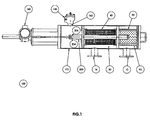
- FIG. 1 is a cross sectional view of a filtering system, according to an embodiment of the invention.
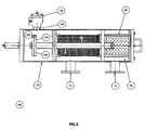
- FIG. 2 is a cross sectional view of a filtering system, according to another embodiment of the invention.
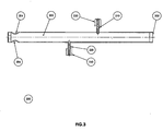
- FIG. 3 is a cross sectional view of a backwash body, according to an embodiment of the invention.
- FIG. 4 is a cross sectional view of a guide and a nozzle, according to an embodiment of the invention.
- FIG. 6 is a cross sectional view of a guide and a nozzle, according to another embodiment of the invention.
- FIG. 7 is a cross sectional view of a guide and a nozzle, according to a further embodiment of the invention.
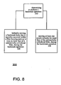
- FIG. 8 is a flow chart illustrating a method for cleaning a filtering system, according to an embodiment of the invention.
- FIG. 1 is a cross sectional view of filtering system 100, according to an embodiment of the invention.
- the cross section is made along an imaginary longitudinal axis of the filtering system.
- Filtering system 100 can include one or more filters. It usually includes a coarse filter as well as a fine filter. For simplicity of explanation it is assumed that filtering system 100 includes a cylindrical coarse filter 20 and a substantially cylindrical filter 40 that is also refereed to as fine filter 40.
- the coarse filter 20 can be subjected to a backwash operation, but this is not necessarily so.
- backwash operation of fine filter 40 refers to backwash operation of fine filter 40.
- Filtering system 100 includes an elongated tube shaped housing 170 having fluid inlet 10 for a connection with a fluid supply duct (not illustrated), through which the fluid enters a preliminary filtering chamber 90.
- the preliminary filtering chamber 90 is opened to a final filtering chamber 30 through the coarse filter 20 that is adapted to removing rough particles from the fluid.
- the pre-filtered fluid which passes the coarse filter 20 flows through the fine filter 40 to the filtered fluid chamber 30 and to the fluid outlet 160 adapted for a connection with a filtered fluid duct (not illustrated).
- the preliminary filtering chamber 90 and the filtered fluid chamber 30 are two compartments within one tube shaped envelope.
- a backwash body 200 is movably mounted within the filter housing 170.
- the backwash body 200 includes an elongated hollow portion 202 (of FIG. 3 ), and at least one hollow guide, such as guides 210 and 220 (of FIG. 3 ), that extend from the hollow portion 202 towards the fine filter 40.
- the backwash body 200 is in contact with at least one nozzle, such as nozzles 230 and 240 (of FIG. 3 ) that can move, conveniently along guides 210 and 220, towards the inner face of the fine filter 40 during a backwash operation.
- the elongated hollow portion 202 includes one or more outlets, such as outlets 204 and 206 (of FIG. 3 ) that are located within the filtered fluid chamber 30.
- the nozzle 230 further move towards the inner face of fine filter 40 such as to increase the efficiency of the backwash operation.
- the nozzles further perform a radial movement towards the inner face of fine filter 40.
- the backwash operation is usually activated according to a differential pressure sensor gauge that is adapted for identifying a predetermined differential pressure between different portions of the filtering system, indicating that a certain amount of dirt blocks the filter, thus a cleaning operation is required.
- the backwash operation can be initiated, additionally or alternatively, in a periodic manner, in a random manner, in a quasi-random manner, automatically, manually, in response to a request to perform such as backwash operation, and the like.
- the helical movement can be induced by a motor, by hydraulic mechanisms, automatically or manually, and the like.
- FIG. 1 illustrates filtering system 100 that includes an electrical motor 160 that induces the helical movement.
- the driving mechanism translates the rotation of the motor to a helical movement of the backwash body 200.
- the direction (clockwise or counterclockwise) of the rotation of the backwash body is dictated by the rotation direction of the motor 160.
- the motor 160 can be activated in various manners.
- the direction of the rotation can be switched according to the location of the backwash body 200, in response to the number of rotations and/or in response to rotation periods.
- FIG. 2 is a cross sectional view of filtering system 100', according to an embodiment of the invention.
- Filtering system 100' does not include a motor 160 but includes a backwash body 200 that includes two relatively large hollow guides 250 that are shaped so that the propagation of fluid within the filtered fluid chamber 30 (towards the backwash valve 140) rotates the fins. This rotation is then translated to a helical movement.
- These guides can also be referred to as jets or as an hydraulic motor.
- the nozzles 230 and 240 are hollow such as to allow fluid, dirt and particles to propagate towards the backwash body 200.
- the guides 210 and 220 and accordingly the nozzles 230 and 240 are usually spaced apart from each other. It is further noted that the amount of guides can differ then two. Conveniently, the different guides are positioned such that during the helical movement of the backwash body 200 substantially the entire fine filter 40 is backwashed.
- the suction operation is generated automatically by the pressure-difference between the pressure of the fluid within the filter housing 170 and the pressure of the free atmosphere to which the backwash valve 140 is opened during the backwash operation.
- FIG. 4 is a cross sectional view of guide 210 and nozzle 230, according to an embodiment of the invention.
- Guide 210 has a cylindrical shape.
- FIG. 4 illustrates a guide 210 that includes an upper portion 212 and a lower portion 214.
- the upper portion 212 is thinner than the lower portion 214 such as to define a step 216 that limits the radial movement of nozzle 230 towards the elongated hollow portion 202.
- the nozzle 230 can move along an imaginary radial axis that is substantially perpendicular to the imaginary longitudinal axis of the filtering system 100.
- nozzle 230 moves along guide 210, or at least along upper portion 212, while extending towards the inner part of fine filter 40.
- Nozzles 230 can have a cylindrical shape. It is conveniently shaped such as to define an annular space 218 between a portion 232 of the inner face of nozzle 230 and the outer face of guide 210. Another portion 234 of the inner face of nozzle 230 contacts the outer face of guide 210, thus allowing nozzle 230 to move along guide 210.
- the annular space 218 reduces the friction between nozzle 230 and guide 210. It is noted that other shapes (of the nozzle, guides and space) can be used whilst still being in accordance with other embodiments of the present invention.
- a spring 270 placed on the lower portion 214 of guide 210.
- the spring 270 contacts a inner edge 236 of nozzle 230 and forces the nozzle 230 to move towards the inner face of fine filter 40.
- the lower end 236 of nozzle can include an annular recess or annular step that are shaped such as to contact one end of the spring 270.
- the lower end 236 of nozzle 230 can also include a step of a recess that is shaped according to step 216 of guide 210.
- FIG. 4 illustrates a spring 270 that cause the nozzle 230 to track a pattern defined by the inner face of the fine filter 40, and optionally by dirt that is positioned between the nozzle and the inner face of the fine filter 40.
- the nozzle can be shaped such that the fluid within the filter housing forces the nozzle to substantially contact the inner face of fine filter 40 during the backwash operation.
- the centrifugal force and/or gravity force the nozzle to move towards the inner face of fine filter 40.
- the fluid forces the nozzle to maintain in proximity to the inner face of the fine filter 40 (or near dirt positioned between the nozzle 230 and the inner face of the fine filter 40).
- FIG. 5 is a cross sectional view of a guide 220 and a nozzle 240, according to another embodiment of the invention.
- Nozzle 240 includes an outer edge 242 and an inner edge 244.
- the outer edge 242 faces an inner face of fine filter 40.
- the area of the outer edge 242 is smaller than the area of the inner edge 244.
- an upper portion of nozzle that is defined by the outer edge 242 is thinner that a lower portion of the nozzle as defined by the inner edge 244 of nozzle 240. This can be achieved in various manners such as but not limited by defining an annular recess 246 within outer edge 244.
- outer edge 244 can be shaped in various manners.
- the shape of outer edge 244 may correspond to the shape of fine filter 40. It can be curved, include multiple angled surfaces and the like.
- FIG. 6 is a cross sectional view of a guide 210' and a nozzle 230', according to a further embodiment of the invention.
- Guide 210' includes an annular recess 211' and a ring 213' that is partially located within the annular recess 211'.
- the ring 213' limits the movement of nozzle 230' towards the elongated hollow portion 202.
- Nozzle 230' is shaped such that during the backwash operation the fluid that flows towards the backwash outlet forces it to maintain in proximity to the inner face of the fine filter 40 (or near dirt positioned between the nozzle 230' and the inner face of the fine filter 40).
- the inner face of nozzle 230' is also shaped such as to define two annular spaces between the inner face of nozzle 230' and the outer face of guide 210'.
- FIG. 7 illustrates two possible positions of a nozzle, according to an embodiment of the invention.
- Nozzle 230 can move between two positions - an upper position 280 (closer to the inner face of fine filter 40) and a lower position 290 (closer to the elongated hollow portion 202).
- the guide 210 is illustrated as having a recess 215 for easing the fastening of the guide 210.
- FIG. 8 is a flow chart illustrating method 300 for cleaning a filtering system, according to an embodiment of the invention.
- Method 300 starts by stage 310 of determining to perform a backwash operation.
- Stage 310 is followed by stages 320 and 330.
- Stage 320 includes helically moving a backwash body that is movably mounted within a filter housing such as to scan an inner face of a substantially cylindrical filter, during the backwash operation.
- Stage 330 includes moving at least one nozzle towards the inner face of the substantially cylindrical filter, during the backwash operation.
- Stages 320 and 330 can be continued until the backwash operation terminates. Conveniently once the backwash operation terminates a filtering process initiates.
- stage 330 includes moving the at least one nozzle until it contacts at least one of the following: (i) an inner face of the substantially cylindrical filter, and (ii) dirt that is positioned between the inner face of the substantially cylindrical filter and the nozzle.
- stage 330 includes moving the at least one nozzle until it loosely contacts an inner face of the substantially cylindrical filter or dirt that is positioned between the inner face of the substantially cylindrical filter and the nozzle.
- stage 330 includes moving the at least one nozzle until it is positioned at a small distance from at least one of the following: (i) an inner face of the substantially cylindrical filter, and (ii) dirt that is positioned between the inner face of the substantially cylindrical filter and the nozzle.
- stage 330 includes moving the at least one nozzle by the fluid within the filter housing.
- stage 330 can include maintaining, by the fluid that flows during the backwash operation, the at least one nozzle in proximity to the inner face of the substantially cylindrical filter.
- the fluid can cause the at least one nozzle to contact (and even loosely contact) the inner face of the substantially cylindrical filter or dirt that is positioned between the inner face of the substantially cylindrical filter and the nozzle.
- stage 330 involves moving the at least one nozzle by a spring.
Landscapes
- Chemical & Material Sciences (AREA)
- Chemical Kinetics & Catalysis (AREA)
- Filtering Of Dispersed Particles In Gases (AREA)
- Filtration Of Liquid (AREA)
- Nozzles (AREA)
Claims (20)
- Système de filtration (100) comprenant :- un boîtier de filtre (170) comprenant une entrée de fluide (10) et une sortie de fluide (16) ;- un filtre disposé à l'intérieur du boîtier de filtre ;- un corps de lavage à contre-courant (200) monté de manière mobile à l'intérieur du boîtier de filtre (170) pour effectuer un mouvement hélicoïdal tout en lavant à contre-courant le filtre (40) ; et- au moins une buse (230, 230', 240) en liaison avec le corps de lavage à contre-courant,caractérisé par le fait que- le filtre est un filtre sensiblement cylindrique (40) :- la au moins une buse est apte à se déplacer vers le filtre sensiblement cylindrique, de telle sorte que, lors d'une opération de lavage à contre-courant, lorsque la buse effectue un mouvement hélicoïdal et se trouve à proximité de la surface interne du filtre cylindrique (40), la buse est maintenue à proximité d'une face interne du filtre sensiblement cylindrique ou à proximité de la saleté positionnée entre la buse et une face interne du filtre sensiblement cylindrique ;- la au moins une buse se déplaçant entre deux positions - une position supérieure qui est plus proche de la face interne du filtre cylindrique et une position inférieure qui est plus proche d'une partie creuse allongée du corps de lavage à contre-courant ;- la au moins une buse étant façonnée de telle sorte qu'un fluide à l'intérieur du boîtier de filtre (170) force la au moins une buse à se déplacer vers le filtre sensiblement cylindrique (40) lors de l'opération de lavage à contre-courant ; et- le système comprenant une jauge de capteur de pression différentielle qui active l'opération de lavage à contre-courant.
- Système de filtration (100) selon la revendication 1, dans lequel la au moins une buse (230, 230', 240) est apte à venir en contact, lors de l'opération de lavage à contre-courant, avec au moins l'une parmi ce qui suit :(i) une face interne du filtre sensiblement cylindrique (40), et(ii) de la saleté qui est positionnée entre la face interne du filtre sensiblement cylindrique (40) et la buse (230, 230', 240).
- Système de filtration (100) selon la revendication 1, dans lequel la au moins une buse (230, 230', 240) est apte à venir en contact de manière lâche, lors de l'opération de lavage à contre-courant, avec au moins l'une parmi ce qui suit :(i) une face interne du filtre sensiblement cylindrique (40), et(ii) de la saleté qui est positionnée entre la face interne du filtre sensiblement cylindrique (40) et la buse (230, 230', 240).
- Système de filtration (100) selon la revendication 1, dans lequel la au moins une buse (230, 230', 240) est apte à être positionnée à proximité d'au moins l'une parmi ce qui suit :(i) une face interne du filtre sensiblement cylindrique (40), et(ii) de la saleté qui est positionnée entre la face interne du filtre sensiblement cylindrique (40) et la buse (230, 230', 240).
- Système de filtration (100) selon l'une quelconque des revendications précédentes, dans lequel un bord externe (242) de la buse (230, 230', 240) est dirigé vers une face interne du filtre sensiblement cylindrique (40) et une surface du bord externe (242) étant plus petite qu'une surface d'un bord interne (244) de la buse (230, 230', 240).
- Système de filtration (100) selon l'une quelconque des revendications précédentes, dans lequel la au moins une buse (230, 230', 240) est façonnée de telle sorte que le fluide à l'intérieur du boîtier de filtre (170) force la buse (230, 230', 240) à venir en contact, lors de l'opération de lavage à contre-courant, avec au moins l'une parmi ce qui suit :(i) une face interne du filtre sensiblement cylindrique (40), et(ii) de la saleté qui est positionnée entre la face interne du filtre sensiblement cylindrique (40) et la buse (230, 230', 240).
- Système de filtration (100) selon l'une quelconque des revendications précédentes, dans lequel le corps de lavage à contre-courant (200) comprend en outre un ressort (270) qui force une buse correspondante (230, 230', 240) à se déplacer vers le filtre sensiblement cylindrique (40).
- Système de filtration (100) selon l'une quelconque des revendications précédentes, dans lequel un corps de lavage à contre-courant (200) comprend en outre un ressort (270) qui force une buse correspondante (230, 230', 240) à venir en contact, lors de l'opération de lavage à contre-courant, avec au moins l'une parmi ce qui suit :(i) une face interne du filtre sensiblement cylindrique (40), et(ii) de la saleté qui est positionnée entre la face interne du filtre sensiblement cylindrique (40) et la buse (230, 230', 240).
- Système de filtration (100) selon l'une quelconque des revendications précédentes, comprenant en outre au moins un élément de limitation de buse pour limiter un déplacement d'au moins une buse correspondante (230, 230', 240).
- Système de filtration (100) selon l'une quelconque des revendications précédentes, dans lequel le corps de lavage à contre-courant (200) comprend au moins un guide creux et au moins une buse (230, 230', 240) étant apte à se déplacer le long d'un guide creux correspondant.
- Procédé (300) pour le nettoyage d'un système de filtration (100), le procédé comprenant l'étape consistant à :- déterminer (310) la réalisation d'une opération de lavage à contre-courant ;caractérisé par le fait que le procédé comprend en outre les étapes consistant à :- déplacer de manière hélicoïdale (320) un corps de lavage à contre-courant (200) qui est monté de manière mobile à l'intérieur d'un boîtier de filtre (170) de façon à balayer une face interne d'un filtre sensiblement cylindrique (40), lors de l'opération de lavage à contre-courant ; et- déplacer (330), par la force du fluide à l'intérieur du boîtier de filtre (170), au moins une buse (230, 230', 240) vers la face interne du filtre sensiblement cylindrique (40), lors de l'opération de lavage à contre-courant ;- la au moins une buse se déplaçant entre deux positions - une position supérieure qui est plus proche de la face interne du filtre cylindrique et une position inférieure qui est plus proche d'une partie creuse allongée du corps de lavage à contre-courant.
- Procédé selon la revendication 11, dans lequel le déplacement comprend le déplacement de la au moins une buse (230, 230', 240) jusqu'à ce qu'elle soit en contact avec au moins l'une parmi ce qui suit :(i) une face interne du filtre sensiblement cylindrique (40), et(ii) de la saleté qui est positionnée entre la face interne du filtre sensiblement cylindrique (40) et la buse (230, 230', 240).
- Procédé selon la revendication 11, dans lequel le déplacement comprend le déplacement du au moins un élément radial de lavage à contre-courant jusqu'à ce qu'il soit en contact de manière lâche avec au moins l'une parmi ce qui suit :(i) une face interne du filtre sensiblement cylindrique (40), et(ii) de la saleté qui est positionnée entre la face interne du filtre sensiblement cylindrique (40) et la buse (230, 230', 240).
- Procédé selon la revendication 11, dans lequel le déplacement comprend le déplacement de la au moins une buse (230, 230', 240) jusqu'à ce qu'elle soit positionnée à une faible distance d'au moins l'une parmi ce qui suit :(i) une face interne du filtre sensiblement cylindrique (40), et(ii) de la saleté qui est positionnée entre la face interne du filtre sensiblement cylindrique (40) et la buse (230, 230', 240).
- Procédé selon la revendication 11, dans lequel le déplacement comprend le déplacement de la au moins une buse (230, 230', 240) jusqu'à ce qu'elle soit en contact avec au moins l'une parmi ce qui suit :(i) une face interne du filtre sensiblement cylindrique (40), et(ii) de la saleté qui est positionnée entre la face interne du filtre sensiblement cylindrique (40) et la buse (230, 230', 240).
- Procédé selon l'une quelconque des revendications 11 à 15, dans lequel le déplacement comprend le déplacement de la au moins une buse (230, 230', 240) par au moins un ressort correspondant.
- Procédé selon la revendication 16, dans lequel le déplacement comprend le déplacement de la au moins une buse (230, 230', 240) jusqu'à ce qu'elle soit en contact avec au moins l'une parmi ce qui suit :(i) une face interne du filtre sensiblement cylindrique (40), et(ii) de la saleté qui est positionnée entre la face interne du filtre sensiblement cylindrique (40) et la buse (230, 230', 240).
- Procédé selon l'une quelconque des revendications 11 à 17, comprenant le maintien, lors de l'opération de lavage à contre-courant, la au moins une buse (230, 230', 240) à proximité d'au moins l'une parmi ce qui suit :(i) une face interne du filtre sensiblement cylindrique (40), et(ii) de la saleté qui est positionnée entre la face interne du filtre sensiblement cylindrique (40) et la buse (230, 230', 240).
- Procédé selon l'une quelconque des revendications 11 à 18, comprenant le maintien, par un fluide qui s'écoule lors de l'opération de lavage à contre-courant, la au moins une buse (230, 230', 240) à proximité d'au moins l'une parmi ce qui suit :(i) une face interne du filtre sensiblement cylindrique (40), et(ii) de la saleté qui est positionnée entre la face interne du filtre sensiblement cylindrique (40) et la buse (230, 230', 240).
- Procédé selon l'une quelconque des revendications 11 à 18, comprenant le maintien, par un fluide qui s'écoule lors de l'opération de lavage à contre-courant, la au moins une buse (230, 230', 240) en contact avec au moins l'une parmi ce qui suit :(i) une face interne du filtre sensiblement cylindrique (40), et(ii) de la saleté qui est positionnée entre la face interne du filtre sensiblement cylindrique (40) et la buse (230, 230', 240).
Priority Applications (4)
| Application Number | Priority Date | Filing Date | Title |
|---|---|---|---|
| ES05257010T ES2371347T3 (es) | 2005-11-14 | 2005-11-14 | Procedimiento de limpieza de un sistema de filtrado y un sistema de filtrado que tiene capacidades de limpieza. |
| AT05257010T ATE515303T1 (de) | 2005-11-14 | 2005-11-14 | Methode zur filterreinigung und filtrationssystem mit reinigungseinrichtungen |
| US11/273,669 US20070199885A1 (en) | 2005-11-14 | 2005-11-14 | Method for cleaning a filtering system and a filtering system having cleaning capabilities |
| EP05257010A EP1785178B1 (fr) | 2005-11-14 | 2005-11-14 | Procede de nettoyage d'un systeme de filtration et un systeme de filtration ayant un dispositif de nettoyage |
Applications Claiming Priority (2)
| Application Number | Priority Date | Filing Date | Title |
|---|---|---|---|
| US11/273,669 US20070199885A1 (en) | 2005-11-14 | 2005-11-14 | Method for cleaning a filtering system and a filtering system having cleaning capabilities |
| EP05257010A EP1785178B1 (fr) | 2005-11-14 | 2005-11-14 | Procede de nettoyage d'un systeme de filtration et un systeme de filtration ayant un dispositif de nettoyage |
Publications (2)
| Publication Number | Publication Date |
|---|---|
| EP1785178A1 EP1785178A1 (fr) | 2007-05-16 |
| EP1785178B1 true EP1785178B1 (fr) | 2011-07-06 |
Family
ID=42734824
Family Applications (1)
| Application Number | Title | Priority Date | Filing Date |
|---|---|---|---|
| EP05257010A Expired - Lifetime EP1785178B1 (fr) | 2005-11-14 | 2005-11-14 | Procede de nettoyage d'un systeme de filtration et un systeme de filtration ayant un dispositif de nettoyage |
Country Status (3)
| Country | Link |
|---|---|
| US (1) | US20070199885A1 (fr) |
| EP (1) | EP1785178B1 (fr) |
| AT (1) | ATE515303T1 (fr) |
Cited By (1)
| Publication number | Priority date | Publication date | Assignee | Title |
|---|---|---|---|---|
| RU189133U1 (ru) * | 2018-10-05 | 2019-05-13 | Амиад Вотер Системс Лтд. | Универсально подсоединяемая фильтровальная система |
Families Citing this family (18)
| Publication number | Priority date | Publication date | Assignee | Title |
|---|---|---|---|---|
| JP5143226B2 (ja) * | 2007-05-30 | 2013-02-13 | ドミニオン エンジニアリング、インコーポレイテッド | 超音波再生を用いてフィルタ能力を向上する装置と方法 |
| US20090050582A1 (en) | 2007-08-23 | 2009-02-26 | Shmuel Gil | Self-Cleaning System For Filter |
| CN102712018B (zh) * | 2009-11-12 | 2015-10-07 | 过滤器安全有限公司 | 过滤器近端喷嘴 |
| KR20140030092A (ko) * | 2010-08-20 | 2014-03-11 | 트로잔 테크놀로지스 | 유체 필터 장치 |
| US8647516B2 (en) * | 2010-09-03 | 2014-02-11 | Johnny Leon LOVE | Filtration method with self-cleaning filter assembly |
| GB2487404A (en) | 2011-01-20 | 2012-07-25 | Sea Lix As | Rotor for extracting energy from bidirectional fluid flows |
| US20130026111A1 (en) * | 2011-05-23 | 2013-01-31 | Odis Irrigation Equipment Ltd. | Filtering system with backwash capabilities |
| GB2500900B (en) * | 2012-04-04 | 2019-10-16 | Sea Lix As | Filter Cleaning |
| US9561454B2 (en) * | 2012-10-09 | 2017-02-07 | Ovivo Inc. | Debris filter with splitter bar |
| HK1223085A1 (zh) * | 2013-09-12 | 2017-07-21 | 安特尔处理设施建设工贸股份公司 | 带有电机减速器的吸污嘴刷洗式自动清洁过滤器 |
| US9314718B2 (en) * | 2013-11-10 | 2016-04-19 | Yamit Filtration & Water Treatment Ltd | Backwash arrangement for cleaning a cylindrical filter screen |
| NO3110521T3 (fr) | 2014-02-28 | 2018-05-19 | ||
| US10183243B2 (en) * | 2015-07-08 | 2019-01-22 | Filter Safe Ltd | Micronic automatic filter |
| DE102017002646A1 (de) * | 2017-03-18 | 2018-09-20 | Hydac Process Technology Gmbh | Filtervorrichtung |
| IL258698A (en) * | 2018-04-15 | 2018-05-31 | Amiad Water Systems Ltd | A control mechanism for self-cleaning filter systems |
| NO345889B1 (en) * | 2020-02-19 | 2021-09-27 | Tenko As | Filter systems and methods |
| CN111794355B (zh) * | 2020-07-04 | 2021-06-22 | 深圳市润博建设有限公司 | 一种市政管道简易截污装置 |
| CN118341146B (zh) * | 2024-05-10 | 2024-10-11 | 海宁市倍世环保科技有限公司 | 一种机械式压差自动控制排污前置过滤器 |
Family Cites Families (11)
| Publication number | Priority date | Publication date | Assignee | Title |
|---|---|---|---|---|
| AU5250379A (en) | 1978-11-17 | 1980-05-22 | Mordeki Drori | Backwashable filter |
| DE4007893A1 (de) * | 1990-01-06 | 1991-07-11 | Brieden Filtration Gmbh Und Co | Vorrichtung zur klaerung von prozesswasser, insbesondere von kuehlwasser mit hilfe eines siebes |
| GB2265840B (en) * | 1992-04-06 | 1995-05-10 | Locker Wire Weavers Limited | Clarifier and method for cleaning same |
| DE4339268C2 (de) * | 1993-11-18 | 1996-01-25 | Huber Hans Gmbh Maschinen Und | Verfahren und Vorrichtung zum Ausfiltern und Rückspülen von Feststoff-Partikeln aus Flüssigkeiten |
| FR2743505B1 (fr) * | 1996-01-15 | 1998-02-13 | Cellier Groupe Sa | Dispositif de filtration autodecolmatant |
| US6337013B1 (en) * | 1997-12-23 | 2002-01-08 | Ontario Power Generation, Inc. | Removable filter with jack sealing device and vacuum cleaning heads |
| JP3462432B2 (ja) | 1999-07-30 | 2003-11-05 | Smc株式会社 | 逆洗機構付フィルタ装置 |
| US6267879B1 (en) * | 1999-08-11 | 2001-07-31 | Odis Irrigation Equipment Ltd. | Continuous liquid filtering apparatus with multi-layer sintered filtering element |
| US6342163B1 (en) | 1999-11-12 | 2002-01-29 | United States Filter Corporation | Apparatus and method for sanitizing and cleaning a filter system |
| AU2004321592A1 (en) * | 2004-07-21 | 2006-01-26 | Amiad Filtration Systems (1997) Ltd. | Filter cleaning head |
| US7055699B2 (en) * | 2004-09-01 | 2006-06-06 | Amiad Japan Inc. | Self-cleaning mechanical filter |
-
2005
- 2005-11-14 US US11/273,669 patent/US20070199885A1/en not_active Abandoned
- 2005-11-14 EP EP05257010A patent/EP1785178B1/fr not_active Expired - Lifetime
- 2005-11-14 AT AT05257010T patent/ATE515303T1/de not_active IP Right Cessation
Cited By (1)
| Publication number | Priority date | Publication date | Assignee | Title |
|---|---|---|---|---|
| RU189133U1 (ru) * | 2018-10-05 | 2019-05-13 | Амиад Вотер Системс Лтд. | Универсально подсоединяемая фильтровальная система |
Also Published As
| Publication number | Publication date |
|---|---|
| US20070199885A1 (en) | 2007-08-30 |
| ATE515303T1 (de) | 2011-07-15 |
| EP1785178A1 (fr) | 2007-05-16 |
Similar Documents
| Publication | Publication Date | Title |
|---|---|---|
| EP1785178B1 (fr) | Procede de nettoyage d'un systeme de filtration et un systeme de filtration ayant un dispositif de nettoyage | |
| US6267879B1 (en) | Continuous liquid filtering apparatus with multi-layer sintered filtering element | |
| KR101714726B1 (ko) | 필터 근접 노즐 | |
| CN101854994B (zh) | 过滤设备 | |
| EP2027905A2 (fr) | Système autonettoyant pour filtre | |
| KR20070087546A (ko) | 여과기 청소 헤드 | |
| CN1167448A (zh) | 液体过滤设备 | |
| EP3946674A1 (fr) | Tube en spirale à fente(s) pour filtres à pression auto-nettoyants et filtre à pression auto-nettoyant à fente(s) doté d'un tel tube à fente(s) | |
| JP2009517204A (ja) | 洗浄装置 | |
| CN1110930A (zh) | 特别用于流体的可反流冲刷的过滤器 | |
| CN205516800U (zh) | 排污组件及采用该排污组件的自动反冲洗过滤器 | |
| KR20010000766A (ko) | 싸이클론식 연속여과기의 자동 역세 장치 | |
| KR20250078331A (ko) | 자동 회전 역세척 정밀 여과 장치 | |
| CN101279159A (zh) | 一种自动清洗网式过滤器 | |
| KR20250167469A (ko) | 연속 실시간 여과 및 세척기능을 가진 필터시스템 | |
| WO2014118926A1 (fr) | Dispositif de traitement d'eau de ballast | |
| RU2681193C1 (ru) | Система фильтрации для очистки жидких и газообразных сред от механических примесей с автоматической регенерацией высокого давления | |
| KR20250111677A (ko) | 여과망 접촉 차단 가이드 벽체와 보조배출관이 구비된 부상슬러지와 침전슬러지의 연속 분리 배출 장치 | |
| US7396460B2 (en) | Filter element | |
| KR101203634B1 (ko) | 메쉬 가변형 스케일 필터링 장치 | |
| US20110240562A1 (en) | Method and system for backwashing a filter | |
| CN207680154U (zh) | 一种污水处理装置 | |
| KR102733028B1 (ko) | 수직 이동 및 수평 회전하는 세척 노즐이 구비된 부상슬러지와 침전슬러지의 연속 분리 배출 장치 | |
| ES2371347T3 (es) | Procedimiento de limpieza de un sistema de filtrado y un sistema de filtrado que tiene capacidades de limpieza. | |
| KR0175219B1 (ko) | 역전가능스크류홈을 이용한 여과필터의 역세척장치 |
Legal Events
| Date | Code | Title | Description |
|---|---|---|---|
| PUAI | Public reference made under article 153(3) epc to a published international application that has entered the european phase |
Free format text: ORIGINAL CODE: 0009012 |
|
| AK | Designated contracting states |
Kind code of ref document: A1 Designated state(s): AT BE BG CH CY CZ DE DK EE ES FI FR GB GR HU IE IS IT LI LT LU LV MC NL PL PT RO SE SI SK TR |
|
| AX | Request for extension of the european patent |
Extension state: AL BA HR MK YU |
|
| 17P | Request for examination filed |
Effective date: 20071116 |
|
| 17Q | First examination report despatched |
Effective date: 20071228 |
|
| AKX | Designation fees paid |
Designated state(s): AT BE BG CH CY CZ DE DK EE ES FI FR GB GR HU IE IS IT LI LT LU LV MC NL PL PT RO SE SI SK TR |
|
| GRAP | Despatch of communication of intention to grant a patent |
Free format text: ORIGINAL CODE: EPIDOSNIGR1 |
|
| GRAJ | Information related to disapproval of communication of intention to grant by the applicant or resumption of examination proceedings by the epo deleted |
Free format text: ORIGINAL CODE: EPIDOSDIGR1 |
|
| GRAP | Despatch of communication of intention to grant a patent |
Free format text: ORIGINAL CODE: EPIDOSNIGR1 |
|
| GRAS | Grant fee paid |
Free format text: ORIGINAL CODE: EPIDOSNIGR3 |
|
| GRAA | (expected) grant |
Free format text: ORIGINAL CODE: 0009210 |
|
| AK | Designated contracting states |
Kind code of ref document: B1 Designated state(s): AT BE BG CH CY CZ DE DK EE ES FI FR GB GR HU IE IS IT LI LT LU LV MC NL PL PT RO SE SI SK TR |
|
| REG | Reference to a national code |
Ref country code: GB Ref legal event code: FG4D |
|
| REG | Reference to a national code |
Ref country code: CH Ref legal event code: EP |
|
| REG | Reference to a national code |
Ref country code: IE Ref legal event code: FG4D |
|
| REG | Reference to a national code |
Ref country code: DE Ref legal event code: R096 Ref document number: 602005028839 Country of ref document: DE Effective date: 20110825 |
|
| REG | Reference to a national code |
Ref country code: NL Ref legal event code: T3 |
|
| PG25 | Lapsed in a contracting state [announced via postgrant information from national office to epo] |
Ref country code: SI Free format text: LAPSE BECAUSE OF FAILURE TO SUBMIT A TRANSLATION OF THE DESCRIPTION OR TO PAY THE FEE WITHIN THE PRESCRIBED TIME-LIMIT Effective date: 20110706 |
|
| REG | Reference to a national code |
Ref country code: ES Ref legal event code: FG2A Ref document number: 2371347 Country of ref document: ES Kind code of ref document: T3 Effective date: 20111230 |
|
| REG | Reference to a national code |
Ref country code: AT Ref legal event code: MK05 Ref document number: 515303 Country of ref document: AT Kind code of ref document: T Effective date: 20110706 |
|
| REG | Reference to a national code |
Ref country code: GR Ref legal event code: EP Ref document number: 20110402339 Country of ref document: GR Effective date: 20111117 |
|
| PG25 | Lapsed in a contracting state [announced via postgrant information from national office to epo] |
Ref country code: FI Free format text: LAPSE BECAUSE OF FAILURE TO SUBMIT A TRANSLATION OF THE DESCRIPTION OR TO PAY THE FEE WITHIN THE PRESCRIBED TIME-LIMIT Effective date: 20110706 Ref country code: PT Free format text: LAPSE BECAUSE OF FAILURE TO SUBMIT A TRANSLATION OF THE DESCRIPTION OR TO PAY THE FEE WITHIN THE PRESCRIBED TIME-LIMIT Effective date: 20111107 Ref country code: IS Free format text: LAPSE BECAUSE OF FAILURE TO SUBMIT A TRANSLATION OF THE DESCRIPTION OR TO PAY THE FEE WITHIN THE PRESCRIBED TIME-LIMIT Effective date: 20111106 Ref country code: LT Free format text: LAPSE BECAUSE OF FAILURE TO SUBMIT A TRANSLATION OF THE DESCRIPTION OR TO PAY THE FEE WITHIN THE PRESCRIBED TIME-LIMIT Effective date: 20110706 Ref country code: BE Free format text: LAPSE BECAUSE OF FAILURE TO SUBMIT A TRANSLATION OF THE DESCRIPTION OR TO PAY THE FEE WITHIN THE PRESCRIBED TIME-LIMIT Effective date: 20110706 Ref country code: SE Free format text: LAPSE BECAUSE OF FAILURE TO SUBMIT A TRANSLATION OF THE DESCRIPTION OR TO PAY THE FEE WITHIN THE PRESCRIBED TIME-LIMIT Effective date: 20110706 |
|
| PG25 | Lapsed in a contracting state [announced via postgrant information from national office to epo] |
Ref country code: PL Free format text: LAPSE BECAUSE OF FAILURE TO SUBMIT A TRANSLATION OF THE DESCRIPTION OR TO PAY THE FEE WITHIN THE PRESCRIBED TIME-LIMIT Effective date: 20110706 Ref country code: LV Free format text: LAPSE BECAUSE OF FAILURE TO SUBMIT A TRANSLATION OF THE DESCRIPTION OR TO PAY THE FEE WITHIN THE PRESCRIBED TIME-LIMIT Effective date: 20110706 Ref country code: CY Free format text: LAPSE BECAUSE OF FAILURE TO SUBMIT A TRANSLATION OF THE DESCRIPTION OR TO PAY THE FEE WITHIN THE PRESCRIBED TIME-LIMIT Effective date: 20110706 Ref country code: AT Free format text: LAPSE BECAUSE OF FAILURE TO SUBMIT A TRANSLATION OF THE DESCRIPTION OR TO PAY THE FEE WITHIN THE PRESCRIBED TIME-LIMIT Effective date: 20110706 |
|
| PG25 | Lapsed in a contracting state [announced via postgrant information from national office to epo] |
Ref country code: CZ Free format text: LAPSE BECAUSE OF FAILURE TO SUBMIT A TRANSLATION OF THE DESCRIPTION OR TO PAY THE FEE WITHIN THE PRESCRIBED TIME-LIMIT Effective date: 20110706 Ref country code: SK Free format text: LAPSE BECAUSE OF FAILURE TO SUBMIT A TRANSLATION OF THE DESCRIPTION OR TO PAY THE FEE WITHIN THE PRESCRIBED TIME-LIMIT Effective date: 20110706 |
|
| PLBE | No opposition filed within time limit |
Free format text: ORIGINAL CODE: 0009261 |
|
| STAA | Information on the status of an ep patent application or granted ep patent |
Free format text: STATUS: NO OPPOSITION FILED WITHIN TIME LIMIT |
|
| PG25 | Lapsed in a contracting state [announced via postgrant information from national office to epo] |
Ref country code: EE Free format text: LAPSE BECAUSE OF FAILURE TO SUBMIT A TRANSLATION OF THE DESCRIPTION OR TO PAY THE FEE WITHIN THE PRESCRIBED TIME-LIMIT Effective date: 20110706 Ref country code: RO Free format text: LAPSE BECAUSE OF FAILURE TO SUBMIT A TRANSLATION OF THE DESCRIPTION OR TO PAY THE FEE WITHIN THE PRESCRIBED TIME-LIMIT Effective date: 20110706 |
|
| 26N | No opposition filed |
Effective date: 20120411 |
|
| PG25 | Lapsed in a contracting state [announced via postgrant information from national office to epo] |
Ref country code: DK Free format text: LAPSE BECAUSE OF FAILURE TO SUBMIT A TRANSLATION OF THE DESCRIPTION OR TO PAY THE FEE WITHIN THE PRESCRIBED TIME-LIMIT Effective date: 20110706 Ref country code: MC Free format text: LAPSE BECAUSE OF NON-PAYMENT OF DUE FEES Effective date: 20111130 |
|
| REG | Reference to a national code |
Ref country code: CH Ref legal event code: PL |
|
| PG25 | Lapsed in a contracting state [announced via postgrant information from national office to epo] |
Ref country code: CH Free format text: LAPSE BECAUSE OF NON-PAYMENT OF DUE FEES Effective date: 20111130 Ref country code: LI Free format text: LAPSE BECAUSE OF NON-PAYMENT OF DUE FEES Effective date: 20111130 |
|
| REG | Reference to a national code |
Ref country code: DE Ref legal event code: R097 Ref document number: 602005028839 Country of ref document: DE Effective date: 20120411 |
|
| REG | Reference to a national code |
Ref country code: IE Ref legal event code: MM4A |
|
| REG | Reference to a national code |
Ref country code: DE Ref legal event code: R119 Ref document number: 602005028839 Country of ref document: DE Effective date: 20120601 |
|
| PG25 | Lapsed in a contracting state [announced via postgrant information from national office to epo] |
Ref country code: IE Free format text: LAPSE BECAUSE OF NON-PAYMENT OF DUE FEES Effective date: 20111114 |
|
| PGFP | Annual fee paid to national office [announced via postgrant information from national office to epo] |
Ref country code: FR Payment date: 20121130 Year of fee payment: 8 |
|
| PGFP | Annual fee paid to national office [announced via postgrant information from national office to epo] |
Ref country code: ES Payment date: 20121127 Year of fee payment: 8 Ref country code: GR Payment date: 20121128 Year of fee payment: 8 Ref country code: GB Payment date: 20121120 Year of fee payment: 8 Ref country code: IT Payment date: 20121122 Year of fee payment: 8 |
|
| PGFP | Annual fee paid to national office [announced via postgrant information from national office to epo] |
Ref country code: NL Payment date: 20121120 Year of fee payment: 8 |
|
| PG25 | Lapsed in a contracting state [announced via postgrant information from national office to epo] |
Ref country code: LU Free format text: LAPSE BECAUSE OF NON-PAYMENT OF DUE FEES Effective date: 20111114 |
|
| PG25 | Lapsed in a contracting state [announced via postgrant information from national office to epo] |
Ref country code: BG Free format text: LAPSE BECAUSE OF FAILURE TO SUBMIT A TRANSLATION OF THE DESCRIPTION OR TO PAY THE FEE WITHIN THE PRESCRIBED TIME-LIMIT Effective date: 20111006 Ref country code: DE Free format text: LAPSE BECAUSE OF NON-PAYMENT OF DUE FEES Effective date: 20120601 |
|
| PG25 | Lapsed in a contracting state [announced via postgrant information from national office to epo] |
Ref country code: TR Free format text: LAPSE BECAUSE OF FAILURE TO SUBMIT A TRANSLATION OF THE DESCRIPTION OR TO PAY THE FEE WITHIN THE PRESCRIBED TIME-LIMIT Effective date: 20110706 |
|
| PG25 | Lapsed in a contracting state [announced via postgrant information from national office to epo] |
Ref country code: HU Free format text: LAPSE BECAUSE OF FAILURE TO SUBMIT A TRANSLATION OF THE DESCRIPTION OR TO PAY THE FEE WITHIN THE PRESCRIBED TIME-LIMIT Effective date: 20110706 |
|
| REG | Reference to a national code |
Ref country code: NL Ref legal event code: V1 Effective date: 20140601 |
|
| GBPC | Gb: european patent ceased through non-payment of renewal fee |
Effective date: 20131114 |
|
| REG | Reference to a national code |
Ref country code: GR Ref legal event code: ML Ref document number: 20110402339 Country of ref document: GR Effective date: 20140603 |
|
| REG | Reference to a national code |
Ref country code: FR Ref legal event code: ST Effective date: 20140731 |
|
| PG25 | Lapsed in a contracting state [announced via postgrant information from national office to epo] |
Ref country code: IT Free format text: LAPSE BECAUSE OF NON-PAYMENT OF DUE FEES Effective date: 20131114 Ref country code: GR Free format text: LAPSE BECAUSE OF NON-PAYMENT OF DUE FEES Effective date: 20140603 Ref country code: NL Free format text: LAPSE BECAUSE OF NON-PAYMENT OF DUE FEES Effective date: 20140601 |
|
| PG25 | Lapsed in a contracting state [announced via postgrant information from national office to epo] |
Ref country code: FR Free format text: LAPSE BECAUSE OF NON-PAYMENT OF DUE FEES Effective date: 20131202 Ref country code: GB Free format text: LAPSE BECAUSE OF NON-PAYMENT OF DUE FEES Effective date: 20131114 |
|
| REG | Reference to a national code |
Ref country code: ES Ref legal event code: FD2A Effective date: 20150330 |
|
| PG25 | Lapsed in a contracting state [announced via postgrant information from national office to epo] |
Ref country code: ES Free format text: LAPSE BECAUSE OF NON-PAYMENT OF DUE FEES Effective date: 20131115 |