EP1785214B1 - Verfahren zur Herstellung eines Flansches am freien Ende einer Turbinenschaufel, durch diesem Verfahren hergestellte Turbinenschaufel sowie eine mit solcher Turbinenschaufel versehene Turbomaschine - Google Patents
Verfahren zur Herstellung eines Flansches am freien Ende einer Turbinenschaufel, durch diesem Verfahren hergestellte Turbinenschaufel sowie eine mit solcher Turbinenschaufel versehene Turbomaschine Download PDFInfo
- Publication number
- EP1785214B1 EP1785214B1 EP06124100.6A EP06124100A EP1785214B1 EP 1785214 B1 EP1785214 B1 EP 1785214B1 EP 06124100 A EP06124100 A EP 06124100A EP 1785214 B1 EP1785214 B1 EP 1785214B1
- Authority
- EP
- European Patent Office
- Prior art keywords
- blade
- rim
- base
- free end
- source
- Prior art date
- Legal status (The legal status is an assumption and is not a legal conclusion. Google has not performed a legal analysis and makes no representation as to the accuracy of the status listed.)
- Active
Links
Images


Classifications
-
- B—PERFORMING OPERATIONS; TRANSPORTING
- B23—MACHINE TOOLS; METAL-WORKING NOT OTHERWISE PROVIDED FOR
- B23K—SOLDERING OR UNSOLDERING; WELDING; CLADDING OR PLATING BY SOLDERING OR WELDING; CUTTING BY APPLYING HEAT LOCALLY, e.g. FLAME CUTTING; WORKING BY LASER BEAM
- B23K26/00—Working by laser beam, e.g. welding, cutting or boring
- B23K26/34—Laser welding for purposes other than joining
-
- B—PERFORMING OPERATIONS; TRANSPORTING
- B22—CASTING; POWDER METALLURGY
- B22F—WORKING METALLIC POWDER; MANUFACTURE OF ARTICLES FROM METALLIC POWDER; MAKING METALLIC POWDER; APPARATUS OR DEVICES SPECIALLY ADAPTED FOR METALLIC POWDER
- B22F10/00—Additive manufacturing of workpieces or articles from metallic powder
- B22F10/20—Direct sintering or melting
- B22F10/25—Direct deposition of metal particles, e.g. direct metal deposition [DMD] or laser engineered net shaping [LENS]
-
- B—PERFORMING OPERATIONS; TRANSPORTING
- B22—CASTING; POWDER METALLURGY
- B22F—WORKING METALLIC POWDER; MANUFACTURE OF ARTICLES FROM METALLIC POWDER; MAKING METALLIC POWDER; APPARATUS OR DEVICES SPECIALLY ADAPTED FOR METALLIC POWDER
- B22F10/00—Additive manufacturing of workpieces or articles from metallic powder
- B22F10/30—Process control
- B22F10/38—Process control to achieve specific product aspects, e.g. surface smoothness, density, porosity or hollow structures
- B22F10/385—Overhang structures
-
- B—PERFORMING OPERATIONS; TRANSPORTING
- B22—CASTING; POWDER METALLURGY
- B22F—WORKING METALLIC POWDER; MANUFACTURE OF ARTICLES FROM METALLIC POWDER; MAKING METALLIC POWDER; APPARATUS OR DEVICES SPECIALLY ADAPTED FOR METALLIC POWDER
- B22F12/00—Apparatus or devices specially adapted for additive manufacturing; Auxiliary means for additive manufacturing; Combinations of additive manufacturing apparatus or devices with other processing apparatus or devices
- B22F12/50—Means for feeding of material, e.g. heads
- B22F12/53—Nozzles
-
- B—PERFORMING OPERATIONS; TRANSPORTING
- B22—CASTING; POWDER METALLURGY
- B22F—WORKING METALLIC POWDER; MANUFACTURE OF ARTICLES FROM METALLIC POWDER; MAKING METALLIC POWDER; APPARATUS OR DEVICES SPECIALLY ADAPTED FOR METALLIC POWDER
- B22F12/00—Apparatus or devices specially adapted for additive manufacturing; Auxiliary means for additive manufacturing; Combinations of additive manufacturing apparatus or devices with other processing apparatus or devices
- B22F12/50—Means for feeding of material, e.g. heads
- B22F12/58—Means for feeding of material, e.g. heads for changing the material composition, e.g. by mixing
-
- B—PERFORMING OPERATIONS; TRANSPORTING
- B22—CASTING; POWDER METALLURGY
- B22F—WORKING METALLIC POWDER; MANUFACTURE OF ARTICLES FROM METALLIC POWDER; MAKING METALLIC POWDER; APPARATUS OR DEVICES SPECIALLY ADAPTED FOR METALLIC POWDER
- B22F5/00—Manufacture of workpieces or articles from metallic powder characterised by the special shape of the product
- B22F5/04—Manufacture of workpieces or articles from metallic powder characterised by the special shape of the product of turbine blades
-
- B—PERFORMING OPERATIONS; TRANSPORTING
- B22—CASTING; POWDER METALLURGY
- B22F—WORKING METALLIC POWDER; MANUFACTURE OF ARTICLES FROM METALLIC POWDER; MAKING METALLIC POWDER; APPARATUS OR DEVICES SPECIALLY ADAPTED FOR METALLIC POWDER
- B22F7/00—Manufacture of composite layers, workpieces, or articles, comprising metallic powder, by sintering the powder, with or without compacting wherein at least one part is obtained by sintering or compression
- B22F7/06—Manufacture of composite layers, workpieces, or articles, comprising metallic powder, by sintering the powder, with or without compacting wherein at least one part is obtained by sintering or compression of composite workpieces or articles from parts, e.g. to form tipped tools
-
- B—PERFORMING OPERATIONS; TRANSPORTING
- B23—MACHINE TOOLS; METAL-WORKING NOT OTHERWISE PROVIDED FOR
- B23K—SOLDERING OR UNSOLDERING; WELDING; CLADDING OR PLATING BY SOLDERING OR WELDING; CUTTING BY APPLYING HEAT LOCALLY, e.g. FLAME CUTTING; WORKING BY LASER BEAM
- B23K26/00—Working by laser beam, e.g. welding, cutting or boring
- B23K26/14—Working by laser beam, e.g. welding, cutting or boring using a fluid stream, e.g. a jet of gas, in conjunction with the laser beam; Nozzles therefor
- B23K26/144—Working by laser beam, e.g. welding, cutting or boring using a fluid stream, e.g. a jet of gas, in conjunction with the laser beam; Nozzles therefor the fluid stream containing particles, e.g. powder
-
- B—PERFORMING OPERATIONS; TRANSPORTING
- B23—MACHINE TOOLS; METAL-WORKING NOT OTHERWISE PROVIDED FOR
- B23K—SOLDERING OR UNSOLDERING; WELDING; CLADDING OR PLATING BY SOLDERING OR WELDING; CUTTING BY APPLYING HEAT LOCALLY, e.g. FLAME CUTTING; WORKING BY LASER BEAM
- B23K26/00—Working by laser beam, e.g. welding, cutting or boring
- B23K26/14—Working by laser beam, e.g. welding, cutting or boring using a fluid stream, e.g. a jet of gas, in conjunction with the laser beam; Nozzles therefor
- B23K26/1462—Nozzles; Features related to nozzles
- B23K26/1464—Supply to, or discharge from, nozzles of media, e.g. gas, powder, wire
- B23K26/147—Features outside the nozzle for feeding the fluid stream towards the workpiece
-
- B—PERFORMING OPERATIONS; TRANSPORTING
- B23—MACHINE TOOLS; METAL-WORKING NOT OTHERWISE PROVIDED FOR
- B23K—SOLDERING OR UNSOLDERING; WELDING; CLADDING OR PLATING BY SOLDERING OR WELDING; CUTTING BY APPLYING HEAT LOCALLY, e.g. FLAME CUTTING; WORKING BY LASER BEAM
- B23K26/00—Working by laser beam, e.g. welding, cutting or boring
- B23K26/20—Bonding
- B23K26/32—Bonding taking account of the properties of the material involved
-
- B—PERFORMING OPERATIONS; TRANSPORTING
- B23—MACHINE TOOLS; METAL-WORKING NOT OTHERWISE PROVIDED FOR
- B23K—SOLDERING OR UNSOLDERING; WELDING; CLADDING OR PLATING BY SOLDERING OR WELDING; CUTTING BY APPLYING HEAT LOCALLY, e.g. FLAME CUTTING; WORKING BY LASER BEAM
- B23K26/00—Working by laser beam, e.g. welding, cutting or boring
- B23K26/34—Laser welding for purposes other than joining
- B23K26/342—Build-up welding
-
- B—PERFORMING OPERATIONS; TRANSPORTING
- B23—MACHINE TOOLS; METAL-WORKING NOT OTHERWISE PROVIDED FOR
- B23P—METAL-WORKING NOT OTHERWISE PROVIDED FOR; COMBINED OPERATIONS; UNIVERSAL MACHINE TOOLS
- B23P15/00—Making specific metal objects by operations not covered by a single other subclass or a group in this subclass
- B23P15/02—Making specific metal objects by operations not covered by a single other subclass or a group in this subclass turbine or like blades from one piece
-
- B—PERFORMING OPERATIONS; TRANSPORTING
- B23—MACHINE TOOLS; METAL-WORKING NOT OTHERWISE PROVIDED FOR
- B23P—METAL-WORKING NOT OTHERWISE PROVIDED FOR; COMBINED OPERATIONS; UNIVERSAL MACHINE TOOLS
- B23P15/00—Making specific metal objects by operations not covered by a single other subclass or a group in this subclass
- B23P15/04—Making specific metal objects by operations not covered by a single other subclass or a group in this subclass turbine or like blades from several pieces
-
- B—PERFORMING OPERATIONS; TRANSPORTING
- B33—ADDITIVE MANUFACTURING TECHNOLOGY
- B33Y—ADDITIVE MANUFACTURING, i.e. MANUFACTURING OF THREE-DIMENSIONAL [3D] OBJECTS BY ADDITIVE DEPOSITION, ADDITIVE AGGLOMERATION OR ADDITIVE LAYERING, e.g. BY 3D PRINTING, STEREOLITHOGRAPHY OR SELECTIVE LASER SINTERING
- B33Y10/00—Processes of additive manufacturing
-
- B—PERFORMING OPERATIONS; TRANSPORTING
- B33—ADDITIVE MANUFACTURING TECHNOLOGY
- B33Y—ADDITIVE MANUFACTURING, i.e. MANUFACTURING OF THREE-DIMENSIONAL [3D] OBJECTS BY ADDITIVE DEPOSITION, ADDITIVE AGGLOMERATION OR ADDITIVE LAYERING, e.g. BY 3D PRINTING, STEREOLITHOGRAPHY OR SELECTIVE LASER SINTERING
- B33Y80/00—Products made by additive manufacturing
-
- F—MECHANICAL ENGINEERING; LIGHTING; HEATING; WEAPONS; BLASTING
- F01—MACHINES OR ENGINES IN GENERAL; ENGINE PLANTS IN GENERAL; STEAM ENGINES
- F01D—NON-POSITIVE DISPLACEMENT MACHINES OR ENGINES, e.g. STEAM TURBINES
- F01D5/00—Blades; Blade-carrying members; Heating, heat-insulating, cooling or antivibration means on the blades or the members
- F01D5/12—Blades
- F01D5/14—Form or construction
- F01D5/20—Specially-shaped blade tips to seal space between tips and stator
-
- F—MECHANICAL ENGINEERING; LIGHTING; HEATING; WEAPONS; BLASTING
- F01—MACHINES OR ENGINES IN GENERAL; ENGINE PLANTS IN GENERAL; STEAM ENGINES
- F01D—NON-POSITIVE DISPLACEMENT MACHINES OR ENGINES, e.g. STEAM TURBINES
- F01D5/00—Blades; Blade-carrying members; Heating, heat-insulating, cooling or antivibration means on the blades or the members
- F01D5/12—Blades
- F01D5/22—Blade-to-blade connections, e.g. for damping vibrations
- F01D5/225—Blade-to-blade connections, e.g. for damping vibrations by shrouding
-
- B—PERFORMING OPERATIONS; TRANSPORTING
- B23—MACHINE TOOLS; METAL-WORKING NOT OTHERWISE PROVIDED FOR
- B23K—SOLDERING OR UNSOLDERING; WELDING; CLADDING OR PLATING BY SOLDERING OR WELDING; CUTTING BY APPLYING HEAT LOCALLY, e.g. FLAME CUTTING; WORKING BY LASER BEAM
- B23K2101/00—Articles made by soldering, welding or cutting
- B23K2101/001—Turbines
-
- B—PERFORMING OPERATIONS; TRANSPORTING
- B23—MACHINE TOOLS; METAL-WORKING NOT OTHERWISE PROVIDED FOR
- B23K—SOLDERING OR UNSOLDERING; WELDING; CLADDING OR PLATING BY SOLDERING OR WELDING; CUTTING BY APPLYING HEAT LOCALLY, e.g. FLAME CUTTING; WORKING BY LASER BEAM
- B23K2103/00—Materials to be soldered, welded or cut
- B23K2103/08—Non-ferrous metals or alloys
- B23K2103/14—Titanium or alloys thereof
-
- B—PERFORMING OPERATIONS; TRANSPORTING
- B23—MACHINE TOOLS; METAL-WORKING NOT OTHERWISE PROVIDED FOR
- B23K—SOLDERING OR UNSOLDERING; WELDING; CLADDING OR PLATING BY SOLDERING OR WELDING; CUTTING BY APPLYING HEAT LOCALLY, e.g. FLAME CUTTING; WORKING BY LASER BEAM
- B23K2103/00—Materials to be soldered, welded or cut
- B23K2103/18—Dissimilar materials
- B23K2103/26—Alloys of Nickel and Cobalt and Chromium
-
- B—PERFORMING OPERATIONS; TRANSPORTING
- B23—MACHINE TOOLS; METAL-WORKING NOT OTHERWISE PROVIDED FOR
- B23K—SOLDERING OR UNSOLDERING; WELDING; CLADDING OR PLATING BY SOLDERING OR WELDING; CUTTING BY APPLYING HEAT LOCALLY, e.g. FLAME CUTTING; WORKING BY LASER BEAM
- B23K2103/00—Materials to be soldered, welded or cut
- B23K2103/50—Inorganic materials other than metals or composite materials
- B23K2103/52—Ceramics
-
- B—PERFORMING OPERATIONS; TRANSPORTING
- B23—MACHINE TOOLS; METAL-WORKING NOT OTHERWISE PROVIDED FOR
- B23K—SOLDERING OR UNSOLDERING; WELDING; CLADDING OR PLATING BY SOLDERING OR WELDING; CUTTING BY APPLYING HEAT LOCALLY, e.g. FLAME CUTTING; WORKING BY LASER BEAM
- B23K35/00—Rods, electrodes, materials, or media, for use in soldering, welding, or cutting
- B23K35/22—Rods, electrodes, materials, or media, for use in soldering, welding, or cutting characterised by the composition or nature of the material
- B23K35/24—Selection of soldering or welding materials proper
- B23K35/30—Selection of soldering or welding materials proper with the principal constituent melting at less than 1550°C
- B23K35/3033—Ni as the principal constituent
-
- B—PERFORMING OPERATIONS; TRANSPORTING
- B23—MACHINE TOOLS; METAL-WORKING NOT OTHERWISE PROVIDED FOR
- B23K—SOLDERING OR UNSOLDERING; WELDING; CLADDING OR PLATING BY SOLDERING OR WELDING; CUTTING BY APPLYING HEAT LOCALLY, e.g. FLAME CUTTING; WORKING BY LASER BEAM
- B23K35/00—Rods, electrodes, materials, or media, for use in soldering, welding, or cutting
- B23K35/22—Rods, electrodes, materials, or media, for use in soldering, welding, or cutting characterised by the composition or nature of the material
- B23K35/24—Selection of soldering or welding materials proper
- B23K35/30—Selection of soldering or welding materials proper with the principal constituent melting at less than 1550°C
- B23K35/3046—Co as the principal constituent
-
- B—PERFORMING OPERATIONS; TRANSPORTING
- B23—MACHINE TOOLS; METAL-WORKING NOT OTHERWISE PROVIDED FOR
- B23K—SOLDERING OR UNSOLDERING; WELDING; CLADDING OR PLATING BY SOLDERING OR WELDING; CUTTING BY APPLYING HEAT LOCALLY, e.g. FLAME CUTTING; WORKING BY LASER BEAM
- B23K35/00—Rods, electrodes, materials, or media, for use in soldering, welding, or cutting
- B23K35/22—Rods, electrodes, materials, or media, for use in soldering, welding, or cutting characterised by the composition or nature of the material
- B23K35/24—Selection of soldering or welding materials proper
- B23K35/30—Selection of soldering or welding materials proper with the principal constituent melting at less than 1550°C
- B23K35/3053—Fe as the principal constituent
-
- B—PERFORMING OPERATIONS; TRANSPORTING
- B23—MACHINE TOOLS; METAL-WORKING NOT OTHERWISE PROVIDED FOR
- B23K—SOLDERING OR UNSOLDERING; WELDING; CLADDING OR PLATING BY SOLDERING OR WELDING; CUTTING BY APPLYING HEAT LOCALLY, e.g. FLAME CUTTING; WORKING BY LASER BEAM
- B23K35/00—Rods, electrodes, materials, or media, for use in soldering, welding, or cutting
- B23K35/22—Rods, electrodes, materials, or media, for use in soldering, welding, or cutting characterised by the composition or nature of the material
- B23K35/24—Selection of soldering or welding materials proper
- B23K35/32—Selection of soldering or welding materials proper with the principal constituent melting at more than 1550°C
- B23K35/325—Ti as the principal constituent
-
- F—MECHANICAL ENGINEERING; LIGHTING; HEATING; WEAPONS; BLASTING
- F05—INDEXING SCHEMES RELATING TO ENGINES OR PUMPS IN VARIOUS SUBCLASSES OF CLASSES F01-F04
- F05D—INDEXING SCHEME FOR ASPECTS RELATING TO NON-POSITIVE-DISPLACEMENT MACHINES OR ENGINES, GAS-TURBINES OR JET-PROPULSION PLANTS
- F05D2230/00—Manufacture
- F05D2230/30—Manufacture with deposition of material
-
- Y—GENERAL TAGGING OF NEW TECHNOLOGICAL DEVELOPMENTS; GENERAL TAGGING OF CROSS-SECTIONAL TECHNOLOGIES SPANNING OVER SEVERAL SECTIONS OF THE IPC; TECHNICAL SUBJECTS COVERED BY FORMER USPC CROSS-REFERENCE ART COLLECTIONS [XRACs] AND DIGESTS
- Y02—TECHNOLOGIES OR APPLICATIONS FOR MITIGATION OR ADAPTATION AGAINST CLIMATE CHANGE
- Y02P—CLIMATE CHANGE MITIGATION TECHNOLOGIES IN THE PRODUCTION OR PROCESSING OF GOODS
- Y02P10/00—Technologies related to metal processing
- Y02P10/25—Process efficiency
-
- Y—GENERAL TAGGING OF NEW TECHNOLOGICAL DEVELOPMENTS; GENERAL TAGGING OF CROSS-SECTIONAL TECHNOLOGIES SPANNING OVER SEVERAL SECTIONS OF THE IPC; TECHNICAL SUBJECTS COVERED BY FORMER USPC CROSS-REFERENCE ART COLLECTIONS [XRACs] AND DIGESTS
- Y02—TECHNOLOGIES OR APPLICATIONS FOR MITIGATION OR ADAPTATION AGAINST CLIMATE CHANGE
- Y02T—CLIMATE CHANGE MITIGATION TECHNOLOGIES RELATED TO TRANSPORTATION
- Y02T50/00—Aeronautics or air transport
- Y02T50/60—Efficient propulsion technologies, e.g. for aircraft
Definitions
- the invention relates to a method for producing at least one flange located at the free end of a blade, the blade obtained by this method and the turbine engine equipped with such a blade.
- the present invention also relates to a first type of blade whose free end is provided with a plurality of flanges, generally two flanges, parallel to each other, each forming a wiper, than on a second type of hollow blades provided to them. free end of an open cavity or "bath" bordered by this rim.
- the document WO 02/097241 illustrates a dawn of this first type and the document FR 2,858,650 illustrates a dawn of this second type.
- US-A-5,160,822 also describes the blade obtained by this method and a turbomachine comprising such a blade.
- edges have the function of limiting the facing surfaces between the end of the blade and the corresponding annular surface of the turbine housing or compressor, to protect the body of the blade against the damage caused by the possible contact with an annular segment, while ensuring a seal between the rotor and the stator.
- This sealing function at the end of the blades is very important since it conditions the performance of the turbomachine, whether for the efficiency of a turbine stage or a compressor equipped with blades. Indeed, depending on the operating conditions of the turbomachine, there are instability phenomena having the effect of decreasing the efficiency of the turbomachine and / or causing mechanical or thermal overloads of the blades.
- stator seals will wear or abrade depending on the passage of the blades to accommodate the shapes of the latter.
- the blades are provided with rims forming wipers on the radially outer periphery, which are intended to cooperate with the abradable gaskets, these rims themselves having the form of profiled elements, of various shapes, of abrasive material.
- the rim is not in the form of several wipers but a rim, generally continuous, delimiting an open cavity at the free end of the blade, the rim in question playing however the same role.
- these flanges are made by casting simultaneously with the rest of the blade, then they are ground by machining to give them their final shape.
- rims In addition, to avoid damage, see the destruction, rims, especially when in a compressor or a high pressure turbine, we can coat them by thermal spraying (plasma torch, oxygen flame high speed) HVOF, ...) of an abrasive deposit for example of alumina / titanium dioxide or carbide type, for example on an underlayer of aluminum alloy, chromium and nickel, to ensure adhesion.
- thermal spraying plasma torch, oxygen flame high speed HVOF, ...) of an abrasive deposit for example of alumina / titanium dioxide or carbide type, for example on an underlayer of aluminum alloy, chromium and nickel, to ensure adhesion.
- Thermal spraying is a cumbersome technique that requires respect of relative projection angles between the axis of the torch and the surfaces of the parts to be coated, so that the impact of the projected particles is as orthogonal as possible. relative to the surface to be coated in order to obtain satisfactory quality and adherence of the deposit.
- the propellant or plasma-generating gases used for the projection must be easily evacuated without, however, "blowing" the sprayed powder by creating turbulence.
- the object of the present invention is to overcome these disadvantages by proposing a solution that makes it possible to overcome the formation of the flange or rims by casting, which simplifies the foundry tools and avoids the rejection of certain pieces coming out of this foundry stage. .
- the laser projection consists in creating on the part a very localized melt, by the action of a laser beam which can be adjusted very precisely, and in injecting into this melt bath powder (metallic and / or ceramic), which can be abrasive.
- this melt bath powder metallic and / or ceramic
- the laser beam propagates from its source to the target by an optical path.
- This optical path is materialized is not a succession of mirrors that receive the beam and send it in a different direction and optical lenses and converge or diverge or maintain parallel, or by an optical fiber.
- the optical path ends with a system of lenses called "optical head” which converges the beam at a more or less distant point.
- the laser projection device allows a very great flexibility of use when there is no obstacle between the optical head and the point of impact targeted by the beam on the workpiece. Indeed, in the case of thermal spraying, it is necessary for the powder to arrive with a direction of impact normal to the surface to be coated. In a completely different way, with the method proposed according to the present invention, since the laser projection requires only the filling of the melt, the powder can be sent with quite variable paths with respect to the receiving surface.
- the metal powder is dispensed by a powder dispenser. It travels in a tube whose end includes a nozzle that directs the powder to the melt created by the laser beam.
- This tube can be flexible and guided by a rigid support arm or by a robot or other positioning device, or it can be rigid and oriented towards the area to be coated part.
- the nozzle conveying the hot gases must be close to the surface to be coated, whereas in the case of laser projection, the optical head may be relatively far from this surface.
- the powder In the case of thermal spraying, the powder must be heated so that it must have a common trajectory with the hot gases, which is not the case with a laser projection in which the trajectory of the powder can be dissociated. of that of the laser beam.
- the solution according to the present invention avoids having to machine the rim from foundry, which is a relatively difficult location to achieve. Indeed, thanks to the process according to the present invention, is built simultaneously layer by layer, the rim, and if necessary, that its coating with a sufficiently abrasive material.
- this method can realize the construction of the rim over its entire height (in this case, the rim base is simply a location of the free end of the blade) or only the construction of the rim on a part of its height forming its end or tip (in this case, the rim base is a low rim, forming a stub at the free end of the blade, and which comes from the foundry step and the possible grinding step by machining).
- step e) the activation of the laser source and the source of powder material is carried out successively or almost simultaneously so that the localized melt is present at the location on which the laser beam is directed when the powder , which arrives on this same site, impacts this surface.
- this or these flanges can be made of a selected material different from that of the blade, in whole or in part.
- steps d) to f) are carried out as long as the entire surface of the top of the rim base is not coated with a layer and during step g) the rim is constructed by the successive deposition of layers. over the entire surface of the top of the rim base, each layer resulting from the realization of steps d) to f). It can be provided to successively deposit increasingly narrow layers in the transverse direction to the extrados wall and / or intrados.
- the surface of the top of the rim base is traversed in a direction transverse to the intrados and / or extrados wall before shifting in the longitudinal direction which extends between the leading edge and the trailing edge.
- each layer line by line by moving, along this line, the adjustment of the optical head and the nozzle (or moving the end of the blade with respect to the laser projection apparatus ) parallel to the direction transverse to the intrados and / or intrados wall, before shifting in the longitudinal direction of the end of the blade and start a new line until the end of the realization a layer.
- step f the laser source and the source of powder material remain activated.
- the construction of the rim can be carried out continuously by forming successive islands of material, either for the complete formation of the rim, or by sequences each corresponding to the manufacture of a part (for example a complete layer of flange).
- a part for example a complete layer of flange.
- the invention also relates to a rotor blade of a gas turbine engine comprising at least one rim located at the free end, where the rim is obtained by the method according to the present invention presented above.
- this flange is manufactured entirely (over its entire height) or only partly, namely its end portion constituting the vertex, by this process.
- the radially inner portion of the flange is formed of a base previously made by casting with the rest of the blade.
- this blade is part of the rotor of a low pressure or high pressure compressor or a low pressure or high pressure turbine of a turbomachine.
- the present invention relates to a turbomachine comprising a rotor blade of the type mentioned above.
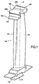
- the figure 1 shows a turbomachine blade 110 of the first type which comprises a blade root 112 at its inner end and a free end 114 forming a heel at its outer peripheral end.
- This blade 110 extends along a radial direction along a blade axis XX 'promoting axial flow, this axis XX' being perpendicular to the axis of the rotor on which this blade 110 is mounted.
- the blade 110 has a profile with a lower surface 116 and an extrados wall 118.
- the blade 110 has two wipers or flanges 128, respectively 1281 and 1282, which extend transversely with respect to the intrados and extrados walls 118 in a substantially rectilinear direction while protruding radially from the free end 114.
- the height of the flanges 1281 and 1282 may equally well be identical between the two flanges and all along these flanges, or may have a variable height, notably an upper height on the side of the wall of the flange. extrados so as to form a "sawtooth" effect from one blade to another. In all cases, the variation of the height remains low and does not exceed for example 0.2 mm to avoid wear of the flange 128.
- this vane 110 of the first type comprises several flanges 128 (in particular two flanges 1281 and 1282) extending between the leading edge 20 and the trailing edge 22 and parallel to each other, forming wipers extending in longitudinal direction and which are separated from each other.
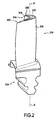
- Cooling air flows inside the blade from the bottom of the root 212 of the blade in the radial (vertical) direction towards the free end 214 of the blade (top on the figure 2 ), then this cooling air escapes through an outlet to join the main gas flow.
- this cooling air circulates in an internal cooling passage 224 situated inside the blade 210 and which ends at the free end 214 of the blade at the open bores 215.
- the body of the blade is profiled so that it defines a lower surface wall 216 (on the left in all the figures) and an extrados wall 218 (on the right in all the figures).
- the intrados wall 216 has a generally concave shape and is the first face to the flow of hot gases, that is to say the gas pressure side, while the extrados wall 218 is convex and is presented by following the flow of hot gases, that is to say the suction side of the gas.
- intrados and extrados walls 218 are joined at the location of the leading edge 220 and at the location of the trailing edge 222 which extend radially between the free end 214 of the blade and the top of the foot 212 of dawn.
- the internal cooling passage 224 is delimited by a bottom wall 226 which extends over the entire free end 214 of the blade, between the pressure side wall 216 and the extrados wall 218, from the leading edge 220 to the trailing edge 222.
- the intrados and extrados walls 216, 218 form the rim 228 of a "bathtub" or open cavity 230 in the opposite direction to the internal cooling passage 224, radially outward (upwards in all figures).
- the through holes 215 through the entire thickness of the bottom wall 226, and communicate the open cavity 230 with the internal cooling passage 224.
- This rim 228 is formed of an extrados rim 2281 and a lower flange 2282 respectively radially outwardly extending (upwardly in all the figures) the extrados wall 218 and the the intrados wall 216, beyond the bottom wall 226 and up to the free end 214 of the blade.
- the flange 228 thus forms a thin wall along the profile of the blade which protects the free end 214 of the blade 210, in particular the bottom wall 226, from contact with the corresponding annular surface of the stator, for example the turbine casing.
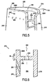
- inclined cooling channels 232 pass through the intrados wall 216 to connect the internal cooling passage 224 to the outside face of the intrados wall 216, below the outer face of the intrados flange 2282.
- These cooling channels 232 are inclined so that they open towards the top of the intrados flange 2282 to cool as much as possible this vertex (arrow 33 on the figure 6 ), along the intrados wall 16, or more precisely along the outer face of the intrados flange 2282.
- the intrados wall 216 has a projecting end portion 234 whose outer face is inclined relative to the outer face of the intrados wall 216, the cooling channels 235 being disposed through this end portion 34.
- the intrados flange 2282 protrudes transversely outwardly at the location of the end portion 234 of the intrados wall 216, so that the outer face of the intrados flange 2282 is inclined and forms an acute angle with the radial direction (vertical on the figure 8 ) or the axis XX 'of the outer face of the remainder of the intrados wall 216, this angle preferably being between 0 and 45 °, in particular between 10 and 35 °, advantageously between 15 and 30 °, and preferably of the order of 30 °.
- FIG 9 represents another variant, according to which the intrados wall 216 no longer has a flange 2281.
- the top of the end portion 234 is orthogonal to the inside walls 216 and the extrados 218 in a direction parallel to the top of the extrados flange 2281, extending the outer surface of the bottom wall 226.
- the extrados rim 2281 has an inner face, turned towards the intrados wall 216 and facing the open cavity 230, extending in an inclined manner, forming an acute angle, ie less than 90 °, with the outer face of the bottom wall 226. In this case, the extrados edge 2281 is therefore wider at its top.
- this blade 210 of the second type (with “bath”) is hollow and includes an internal cooling passage 224, an open cavity 230 located at the free end 214 of the blade 210, and a bottom wall 226. extending over the entire end 214 of the blade, by separating said internal cooling passage 224 from the open cavity 230, said bottom wall 226 having, at the exit of the casting step, a rim base on which the 2281 flange is built by laser projection, layer after layer.
- the outer profile of the flange 2282 has, as it appears on FIG. figure 12 , substantially a shape of inverted V or inverted U with the branches of U inclined towards the top of the flange 2282.
- flange 2282 is provided with an inverted U-shaped cross-sectional profile, with U-branches parallel to each other.
- the rim 2282 is machined directly into the blade 210 at the outlet of the foundry in the form recalled above. Then, if necessary, this flange 2282 may be coated with a deposit made by thermal spraying in order to reinforce its abrasion resistance properties.
- the free end 214 of the cast-off blade 210 has only been machined to provide a base 82 projecting from the upper surface of the bottom wall 226 of the free end 214 of dawn 210 at most a few millimeters, and this to initiate the beginning of the projecting shape of the rim 2282.
- an apparatus (not entirely shown) is used to make a laser projection.
- a first source of a first powder material 35 and a second source of a second powder material 45 are provided, said first source and said second source being connected to the projection nozzle 38.
- the optical head 34 and the nozzle 38 form a same assembly, that is to say that the optical head 34 and the projection nozzle 38 are integral with each other in the same projection assembly whose position is adjustable relative to the blade 210.
- the nozzle 38 may also be located separately beside the laser beam by being supported by a positioning device of its own to enable it to follow the movements of the focal point of the laser beam.
- the point-to-point material can be deposited in different configurations.
- the first layers are made only with the first material 35, then the last layers of the tip 84 come from the mixture between the first material 35 and the second material 45 which may consist of abrasive particles.
- step e) the first source (35) and the second source (45) of powder material are simultaneously activated so that the nozzle (38) projects a mixture of the first and second powder materials 35 and 45.
- the flange 2282 is formed of a base (82) surmounted by a point 84 (V-shaped or inverted U) whose composition varies from its free end 84a.
- the present invention also covers the case in which no flange base 82 is formed beforehand by the casting step of the blade 210, the realization of the entire height of the flange being made by construction as it has been described above, the rim base being reduced in this case (situation not shown) to a portion of the radially outer surface of the free end 214, which corresponds, in the case of the dawn of the second type to a portion of the outer surface of the bottom wall 226.
- the annular beads 83a made with the second powder material 45 form a coating 83 and the central areas filled with the first powder material 35 form the core 85 of the flange 2282.
- the first powder material 35 is identical to that constituting the blade and / or that the second powder material 45 is harder than the first material 35.
- a titanium alloy blade 210 there may be a titanium alloy blade 210, and the flange core 2282 also made of titanium alloy and a coating 83 in a hard and abrasive material, or a flange entirely of a hard and abrasive material.
- a hard and abrasive material particular choice is made among the hot oxidation resistant metals such as a MCrAlY type alloy (M being a metal selected from nickel, cobalt, iron or a mixture of these metals).
- each annular bead 83a is therefore carried out by continuously performing the laser projection deposition by performing a longitudinal displacement of the blade 210, this longitudinal direction extending between the leading edge 220 and the trailing edge 222 .
- the last layer of the flange 2282 will be formed by the same material as the cords 83a, in particular with the second material 45, harder than the first material 35.
- the flange 2282 is formed of a base 82 surmounted by an inverted U-shaped portion or tip 84 composed of a core 85 made of a first material 35, and a coating 83 covering the entire core 85 and realized in a second material 45 harder than that of the soul 85.
- the method proposed according to the present invention avoids on the one hand to perform a delicate machining and on the other hand, when using two different materials between the core and the surface, to perform a coating by a method of thermal projection that can not be done correctly in some geometric configurations.
- the core 85 is preferably a powdered metal material of the same composition as the blade 210, namely a titanium alloy or a nickel-based alloy, and for the coating 83, preferably hard and abrasive materials.
- the hot oxidation-resistant metals such as a MCrAlY type alloy (M being a metal chosen from nickel, cobalt, iron or a mixture of these metals) or an alloy based on cobalt, tungsten chromium such as Stellite (trademark).
- abrasive particles such as ceramics such as titanium dioxide (TiO 2), alumina (ALO 2), zirconia (ZrO 2) or a mixture made from one of they, or else SiC coated with AlN or Al2O3.
- cooling channels 232 connecting the internal cooling passage 224 and the outside face of the intrados wall 216 are pierced at even inside the flange 2282, the intrados wall 216 and any protruding part 234, and therefore after their construction by laser projection.
Landscapes
- Engineering & Computer Science (AREA)
- Mechanical Engineering (AREA)
- Optics & Photonics (AREA)
- Physics & Mathematics (AREA)
- Manufacturing & Machinery (AREA)
- Materials Engineering (AREA)
- Chemical & Material Sciences (AREA)
- Plasma & Fusion (AREA)
- General Engineering & Computer Science (AREA)
- Automation & Control Theory (AREA)
- Composite Materials (AREA)
- Turbine Rotor Nozzle Sealing (AREA)
- Laser Beam Processing (AREA)
Claims (18)
- Verfahren zur Herstellung wenigstens einer Randleiste (128; 228), die sich an dem freien Ende (114; 214) einer Laufschaufel (110; 210) eines Gasturbinentriebwerks befindet, umfassend die folgenden Schritte:a) es wird eine Schaufel (110; 210) bereitgestellt, die an ihrem freien Ende wenigstens eine Basis (82) der Randleiste (128; 228) aufweist,b) es wird eine Spritzdüse (38), die geeignet ist, sich gegenüber der Schaufel (110; 210) zu bewegen, sowie eine erste Quelle (35) eines ersten pulverförmigen Materials und eine zweite Quelle (45) eines zweiten pulverförmigen Materials bereitgestellt, wobei die erste Quelle (35) und die zweite Quelle (45) mit der Spritzdüse (38) verbunden sind,c) es wird eine Laserquelle bereitgestellt, die mit einem optischen Kopf (34) verbunden ist, welcher geeignet ist, sich gegenüber der Schaufel (110; 210) zu bewegen, um den Laserstrahl auf eine Stelle der Oberfläche der Basis (82) der Randleiste (128; 228) zu fokussieren,d) der optische Kopf (34) und die Düse (38) werden auf eine gleiche Stelle der Oberfläche des Scheitels der Basis (82) der Randleiste (128; 228) eingestellt,e) die Laserquelle und die Quellen (35; 45) pulverförmigen Materials werden aktiviert, wodurch ein auf den Bereich der genannten Stelle begrenztes Schmelzbad gebildet wird, in das das pulverförmige Material eingespritzt wird, woraus die Bildung einer örtlich begrenzten Überdicke resultiert,f) der optische Kopf (34) und die Düse (38) werden auf eine weitere Stelle der Oberfläche des Scheitels der Basis (82) eingestellt, die der örtlich begrenzten Überdicke benachbart ist, und man kehrt zu Schritt e) bis zur Bildung einer Schicht über im Wesentlichen die gesamte Breite des Scheitels der Basis (82) zurück;g) es wird wenigstens ein Abschnitt der Randleiste (128; 228) durch das sukzessive Abscheiden von Schichten auf dem Scheitel der Basis (82) hergestellt, wobei jede Schicht aus der Durchführung der Schritte d) bis f) sowie der folgenden Teilschritte resultiert:g1) an der Oberfläche der Basis (82) der Randleiste (128; 228) werden zwei ringförmige Wülste (83a) mit dem zweiten pulverförmigen Material (45) oder einer Mischung aus dem ersten Material (35) und dem zweiten Material (45) dadurch ausgebildet, dass im Laufe des Schrittes f) der optische Kopf (34) und die Düse (38) in Längsrichtung, die zwischen der Vorderkante (120; 220) und der Hinterkante (122; 222) verläuft, gegenüber der zuvor erhaltenen örtlich begrenzten Überdicke versetzt werden, undg2) ein zwischen den beiden ringförmigen Wülsten (83a) befindlicher Bereich (85) wird mit dem ersten pulverförmigen Material (35) gefüllt.
- Verfahren nach dem vorhergehenden Anspruch, dadurch gekennzeichnet, dass die Schritte d) bis f) solange durchgeführt werden, wie die gesamte Oberfläche des Scheitels der Basis (82) der Randleiste (128; 228) nicht mit einer Schicht überzogen ist, und dass während des Schrittes g) die Randleiste (128; 228) durch das sukzessive Abscheiden von Schichten auf der gesamten Oberfläche des Scheitels der Basis (82) der Randleiste (128; 228) hergestellt wird, wobei jede Schicht aus der Durchführung der Schritte d) bis f) resultiert.
- Verfahren nach Anspruch 1 oder 2, dadurch gekennzeichnet, dass während des Schrittes f) die Oberfläche des Scheitels der Basis (82) der Randleiste (128; 228) in einer Richtung quer zu der vorderseitigen Wand (116; 216) und/oder rückseitigen Wand (118; 218) abgeschritten wird, bevor man in Längsrichtung, die zwischen der Vorderkante (120; 220) und der Hinterkante (122; 222) verläuft, einen Platz weiterrückt.
- Verfahren nach einem der vorhergehenden Ansprüche, dadurch gekennzeichnet, dass im Laufe des Schrittes f) die Laserquelle und die Quellen (35; 45) pulverförmigen Materials aktiviert bleiben.
- Verfahren nach dem vorhergehenden Anspruch, dadurch gekennzeichnet, dass das zweite Material (45) härter als das erste Material (35) ist.
- Verfahren nach einem der Ansprüche 1 bis 5, dadurch gekennzeichnet, dass das erste Material (35) mit dem die Schaufel (110; 210) bildenden identisch ist.
- Verfahren nach einem der Ansprüche 1 bis 6, dadurch gekennzeichnet, dass während des Schrittes e) die erste Quelle (35) und die zweite Quelle (45) pulverförmigen Materials gleichzeitig aktiviert werden, so dass die Düse (38) ein Gemisch aus den pulverförmigen Materialien herausspritzt.
- Verfahren nach einem der vorhergehenden Ansprüche, dadurch gekennzeichnet, dass der optische Kopf (34) und die Spritzdüse (38) in einer gleichen Spritzanordnung, deren Position gegenüber der Schaufel (110; 210) einstellbar ist, fest miteinander verbunden sind.
- Verfahren nach einem der vorhergehenden Ansprüche, dadurch gekennzeichnet, dass die Basis (82) der Randleiste (128; 228) in der radialen Verlängerung wenigstens der rückseitigen Wand (118; 218) gelegen ist.
- Laufschaufel (110; 210) eines Gasturbinentriebwerks, umfassend wenigstens eine an dem freien Ende (114; 214) befindliche Randleiste (128; 228), dadurch gekennzeichnet, dass die Randleiste (128; 228) durch das Verfahren nach einem der vorhergehenden Ansprüche erhalten wird.
- Schaufel (110; 210) nach Anspruch 10, dadurch gekennzeichnet, dass die Randleiste (2282) von einer Basis (82) gebildet ist, auf der ein Abschnitt (84) angeordnet ist, der aus einem aus einem ersten Material ausgebildeten Kern (85) und aus einer Beschichtung (83) besteht, die den gesamten Kern (85) überzieht und aus einem zweiten Material, welches härter als das des Kerns (85) ist, ausgebildet ist.
- Schaufel (110; 210) nach Anspruch 10, dadurch gekennzeichnet, dass die Randleiste (2282) von einer Basis (82) gebildet ist, auf der ein Abschnitt (84) angeordnet ist, dessen Zusammensetzung von seinem freien Ende (84a) aus variiert.
- Schaufel (110; 210) nach einem der Ansprüche 10 bis 12, dadurch gekennzeichnet, dass die Randleiste (128; 228) zwischen der Vorderkante (120 oder 220) und der Hinterkante (122 oder 222) verläuft.
- Schaufel (110; 210) nach einem der Ansprüche 10 bis 13, dadurch gekennzeichnet, dass die Randleiste (128; 228) entlang wenigstens der rückseitigen Wand (118 oder 218) verläuft.
- Schaufel (110) nach einem der Ansprüche 10 bis 14, dadurch gekennzeichnet, dass sie mehrere Randleisten (1281, 1282) umfasst, die zwischen der Vorderkante (120) und der Hinterkante (122) sowie parallel zueinander verlaufen.
- Schaufel (210) nach einem der Ansprüche 10 bis 14, dadurch gekennzeichnet, dass die Schaufel hohl ist und einen inneren Kühldurchgang (224), einen an dem freien Ende (214) der Schaufel (210) gelegenen offenen Hohlraum (230) und eine Bodenwand (226), die unter Trennung des inneren Kühldurchgangs (224) von dem offenen Hohlraum (230) über das gesamte Ende (214) der Schaufel verläuft, umfasst, wobei die Bodenwand (226) die Basis (82) der Randleiste (228) aufweist.
- Schaufel (210) nach Anspruch 16, dadurch gekennzeichnet, dass sie ferner Kühlkanäle (232) umfasst, die den inneren Kühldurchgang (224) und die Außenseite der vorderseitigen Wand (216) verbinden, wobei die Kühlkanäle (232) gegenüber der vorderseitigen Wand (216) geneigt sind.
- Turbomaschine, die eine Laufschaufel (110; 210) nach einem der Ansprüche 10 bis 17 umfasst.
Applications Claiming Priority (1)
| Application Number | Priority Date | Filing Date | Title |
|---|---|---|---|
| FR0511578A FR2893268B1 (fr) | 2005-11-15 | 2005-11-15 | Procede de realisation d'un rebord situe a l'extremite libre d'une aube, aube obtenue par ce procede et turbomachine equipee de cette aube |
Publications (3)
| Publication Number | Publication Date |
|---|---|
| EP1785214A2 EP1785214A2 (de) | 2007-05-16 |
| EP1785214A3 EP1785214A3 (de) | 2013-01-09 |
| EP1785214B1 true EP1785214B1 (de) | 2015-02-18 |
Family
ID=36829158
Family Applications (1)
| Application Number | Title | Priority Date | Filing Date |
|---|---|---|---|
| EP06124100.6A Active EP1785214B1 (de) | 2005-11-15 | 2006-11-15 | Verfahren zur Herstellung eines Flansches am freien Ende einer Turbinenschaufel, durch diesem Verfahren hergestellte Turbinenschaufel sowie eine mit solcher Turbinenschaufel versehene Turbomaschine |
Country Status (5)
| Country | Link |
|---|---|
| US (1) | US7695248B2 (de) |
| EP (1) | EP1785214B1 (de) |
| CA (1) | CA2567885C (de) |
| FR (1) | FR2893268B1 (de) |
| RU (1) | RU2415003C2 (de) |
Families Citing this family (37)
| Publication number | Priority date | Publication date | Assignee | Title |
|---|---|---|---|---|
| FR2884550B1 (fr) * | 2005-04-15 | 2010-09-17 | Snecma Moteurs | Piece pour proteger le bord d'attaque d'une pale |
| JP4830812B2 (ja) | 2006-11-24 | 2011-12-07 | 株式会社Ihi | 圧縮機動翼 |
| US20090193656A1 (en) * | 2008-02-04 | 2009-08-06 | General Electric Company | Steam turbine bucket with erosion durability |
| DE102008047043A1 (de) * | 2008-09-13 | 2010-03-18 | Mtu Aero Engines Gmbh | Ersatzteil für eine Gasturbinen-Schaufel einer Gasturbine, Gasturbinen-Schaufel sowie ein Verfahren zur Reparatur einer Gasturbinen-Schaufel |
| DE102009057875A1 (de) * | 2009-12-11 | 2011-06-16 | Mtu Aero Engines Gmbh | Schaufel, insbesondere Leitschaufeln für Verbrennungsturbinen und dessen Herstellung |
| DE102010024226A1 (de) * | 2010-06-18 | 2011-12-22 | Mtu Aero Engines Gmbh | Verfahren und Vorrichtung zur Herstellung oder Reparatur von Bauteilen, insbesondere Bauteilen von Strömungsmaschinen, mittels eines generativen Herstellungsverfahrens |
| US8777567B2 (en) | 2010-09-22 | 2014-07-15 | Honeywell International Inc. | Turbine blades, turbine assemblies, and methods of manufacturing turbine blades |
| ES2773743T3 (es) | 2011-12-13 | 2020-07-14 | Mtu Aero Engines Gmbh | Paleta que tiene un conjunto de nervaduras con un recubrimiento abrasivo |
| EP2614920A1 (de) * | 2012-01-11 | 2013-07-17 | Siemens Aktiengesellschaft | Schweißverfahren mit unterschiedlichem Schweißmaterial, Vorrichtung dafür sowie Bauteil |
| US11000899B2 (en) | 2012-01-29 | 2021-05-11 | Raytheon Technologies Corporation | Hollow airfoil construction utilizing functionally graded materials |
| US20140230212A1 (en) * | 2013-02-20 | 2014-08-21 | Rolls-Royce Corporation | Weld repair of a component |
| EP2799179A1 (de) * | 2013-04-29 | 2014-11-05 | Siemens Aktiengesellschaft | Generatives Verfahren zum Erzeugen eines Endgefüges sowie ein Endgefüge |
| US9856739B2 (en) * | 2013-09-18 | 2018-01-02 | Honeywell International Inc. | Turbine blades with tip portions having converging cooling holes |
| US9879544B2 (en) | 2013-10-16 | 2018-01-30 | Honeywell International Inc. | Turbine rotor blades with improved tip portion cooling holes |
| US9816389B2 (en) | 2013-10-16 | 2017-11-14 | Honeywell International Inc. | Turbine rotor blades with tip portion parapet wall cavities |
| FR3014943B1 (fr) * | 2013-12-18 | 2019-03-29 | Safran Aircraft Engines | Piece de turbomachine a surface non-axisymetrique |
| US9914170B2 (en) * | 2014-06-13 | 2018-03-13 | Hamilton Sundstrand Corporation | Method for making an integrally bladed rotor with hollow blades |
| JP6114718B2 (ja) * | 2014-06-17 | 2017-04-12 | 川崎重工業株式会社 | 軸対称体および軸対称製品の製造方法 |
| US10495103B2 (en) * | 2016-12-08 | 2019-12-03 | United Technologies Corporation | Fan blade having a tip assembly |
| US10830057B2 (en) * | 2017-05-31 | 2020-11-10 | General Electric Company | Airfoil with tip rail cooling |
| CN107470620B (zh) * | 2017-08-15 | 2019-03-08 | 苏州热工研究院有限公司 | 法兰件的电弧增材制造方法 |
| US10787932B2 (en) | 2018-07-13 | 2020-09-29 | Honeywell International Inc. | Turbine blade with dust tolerant cooling system |
| US11426818B2 (en) | 2018-08-10 | 2022-08-30 | The Research Foundation for the State University | Additive manufacturing processes and additively manufactured products |
| US10801334B2 (en) * | 2018-09-12 | 2020-10-13 | Raytheon Technologies Corporation | Cooling arrangement with purge partition |
| CN108817716B (zh) * | 2018-09-18 | 2020-12-11 | 上海交通大学 | 一种适用于小规格孔内激光堆焊的送粉装置 |
| US11131200B2 (en) * | 2018-10-29 | 2021-09-28 | Chromalloy Gas Turbine Llc | Method and apparatus for improving turbine blade sealing in a gas turbine engine |
| FR3099786B1 (fr) * | 2019-08-07 | 2021-07-30 | Safran Helicopter Engines | Aube mobile pour une roue d’une turbomachine |
| DE102019214667A1 (de) * | 2019-09-25 | 2021-03-25 | Siemens Aktiengesellschaft | Komponente mit einem zu kühlenden Bereich und Mittel zur additiven Herstellung derselben |
| US20240229651A9 (en) * | 2019-10-28 | 2024-07-11 | Siemens Energy Global GmbH & Co. KG | Turbine blade, method of manufacturing a turbine blade and method of refurbishing a turbine blade |
| BR112022023888A2 (pt) * | 2020-05-29 | 2022-12-27 | Probono S R L | Máquina e método para a decoração digital de produtos com materiais granulares e similares |
| JP7425708B2 (ja) * | 2020-10-06 | 2024-01-31 | 三菱重工業株式会社 | 動翼 |
| CN112589377B (zh) * | 2020-11-03 | 2022-05-17 | 中信重工机械股份有限公司 | 一种转鼓式汽轮机组装式静叶隔板的制造方法 |
| EP4259905B1 (de) * | 2020-12-08 | 2025-01-29 | General Electric Technology GmbH | Verfahren zur herstellung oder reparatur eines teils mit überhängendem abschnitt und zugehöriges turbomaschinenteil |
| JP7486440B2 (ja) * | 2021-01-14 | 2024-05-17 | 株式会社荏原製作所 | Am装置に使用されるdedノズルおよびdedノズルに着脱可能なアダプタ |
| CN112959013B (zh) * | 2021-03-17 | 2022-07-19 | 中国航发动力股份有限公司 | 一种方钢毛料叶片加工方法 |
| US12228034B2 (en) | 2022-04-28 | 2025-02-18 | Hamilton Sundstrand Corporation | Additively manufactures multi-metallic adaptive or abradable rotor tip seals |
| EP4461927A1 (de) * | 2023-05-12 | 2024-11-13 | Doosan Enerbility Co., Ltd. | Strömungskörper für eine gasturbine, gasturbine, verfahren zur herstellung eines strömungskörpers für eine gasturbine und verfahren zur reparatur eines strömungskörpers einer gasturbine |
Family Cites Families (18)
| Publication number | Priority date | Publication date | Assignee | Title |
|---|---|---|---|---|
| US299366A (en) * | 1884-05-27 | Rag and scrap duster | ||
| US299352A (en) * | 1884-05-27 | Device for thawing out sink-spouts | ||
| US299354A (en) * | 1884-05-27 | covert | ||
| US299363A (en) * | 1884-05-27 | Vehicle-spring | ||
| US4390320A (en) * | 1980-05-01 | 1983-06-28 | General Electric Company | Tip cap for a rotor blade and method of replacement |
| US4884820A (en) * | 1987-05-19 | 1989-12-05 | Union Carbide Corporation | Wear resistant, abrasive laser-engraved ceramic or metallic carbide surfaces for rotary labyrinth seal members |
| US5038014A (en) * | 1989-02-08 | 1991-08-06 | General Electric Company | Fabrication of components by layered deposition |
| US5160822A (en) * | 1991-05-14 | 1992-11-03 | General Electric Company | Method for depositing material on the tip of a gas turbine engine airfoil using linear translational welding |
| RU2058871C1 (ru) * | 1991-06-11 | 1996-04-27 | Акционерное общество открытого типа "Национальный институт авиационных технологий" | Способ лазерной обработки деталей из жаропрочных материалов |
| US5453329A (en) * | 1992-06-08 | 1995-09-26 | Quantum Laser Corporation | Method for laser cladding thermally insulated abrasive particles to a substrate, and clad substrate formed thereby |
| US5900170A (en) * | 1995-05-01 | 1999-05-04 | United Technologies Corporation | Containerless method of producing crack free metallic articles by energy beam deposition with reduced power density |
| RU2100479C1 (ru) * | 1996-01-04 | 1997-12-27 | Научно-исследовательский центр по технологическим лазерам РАН | Способ газопорошковой лазерной наплавки с двухсопловой подачей порошка |
| US6476343B2 (en) * | 1996-07-08 | 2002-11-05 | Sandia Corporation | Energy-beam-driven rapid fabrication system |
| US6122564A (en) * | 1998-06-30 | 2000-09-19 | Koch; Justin | Apparatus and methods for monitoring and controlling multi-layer laser cladding |
| FR2825411B1 (fr) * | 2001-05-31 | 2003-09-19 | Snecma Moteurs | Aube de turbine avec lechette d'etancheite |
| FR2858650B1 (fr) * | 2003-08-06 | 2007-05-18 | Snecma Moteurs | Aube creuse de rotor pour la turbine d'un moteur a turbine a gaz |
| DE102004001722A1 (de) * | 2004-01-13 | 2005-08-04 | Mtu Aero Engines Gmbh | Turbomaschinenschaufel und Verfahren zur Herstellung einer Schaufelspitzenpanzerung an Turbomaschinenschaufeln |
| DE102004002551B4 (de) * | 2004-01-17 | 2007-06-21 | Mtu Aero Engines Gmbh | Verfahren zur Reparatur von Bauteilen |
-
2005
- 2005-11-15 FR FR0511578A patent/FR2893268B1/fr not_active Expired - Lifetime
-
2006
- 2006-11-14 CA CA2567885A patent/CA2567885C/fr active Active
- 2006-11-15 US US11/560,172 patent/US7695248B2/en active Active
- 2006-11-15 RU RU2006140331/02A patent/RU2415003C2/ru active
- 2006-11-15 EP EP06124100.6A patent/EP1785214B1/de active Active
Also Published As
| Publication number | Publication date |
|---|---|
| RU2415003C2 (ru) | 2011-03-27 |
| FR2893268B1 (fr) | 2008-02-08 |
| EP1785214A2 (de) | 2007-05-16 |
| RU2006140331A (ru) | 2008-05-20 |
| CA2567885C (fr) | 2013-12-31 |
| US20070134096A1 (en) | 2007-06-14 |
| US7695248B2 (en) | 2010-04-13 |
| CA2567885A1 (fr) | 2007-05-15 |
| FR2893268A1 (fr) | 2007-05-18 |
| EP1785214A3 (de) | 2013-01-09 |
Similar Documents
| Publication | Publication Date | Title |
|---|---|---|
| EP1785214B1 (de) | Verfahren zur Herstellung eines Flansches am freien Ende einer Turbinenschaufel, durch diesem Verfahren hergestellte Turbinenschaufel sowie eine mit solcher Turbinenschaufel versehene Turbomaschine | |
| EP1785650B1 (de) | Herstellungsverfahren einer Labyrinthschneidendichtung, thermomechanisches Teil und Turbomaschine mit einer solchen Dichtung | |
| EP1785651B1 (de) | Ringförmige Schneidendichtung für eine Labyrinthdichtung und sein Herstellungsverfahren | |
| EP1785649B1 (de) | Rotationssymmetrisches thermomechanisches Teil einer Turbomaschine, ringförmige Labyrinthschneidendichtung und sein Herstellungsverfahren | |
| CA2481939C (fr) | Procede de reparation de pieces metalliques notamment d'aubes de turbine de moteur de turbine a gaz | |
| EP3313597B1 (de) | Verfahren zur herstellung einer klinge mit einer squealer-spitze mit einer kleinen wand | |
| CA2621704C (fr) | Procede de rechargement d'une piece en alliage d'aluminium | |
| EP2260179B1 (de) | Schaufel mit nicht-axialsymmetrischer plattform | |
| US20160069184A1 (en) | Method of blade tip repair | |
| CA2576709A1 (fr) | Procede de fabrication de piece de turbomachine comportant des orifices d'evacuation d'air de refroidissement | |
| CA2719354C (fr) | Procede de fabrication d'un disque aubage monobloc, par decoupe au jet d'eau abrasif | |
| WO2023135336A1 (fr) | Procédé de reconstruction de pièces en superalliage inconel 713 par fabrication additive métallique | |
| EP1481755A1 (de) | Verfahren zur Herstellung einer hohlen Schaufel für Strömungsmaschine | |
| WO2013088078A1 (fr) | Secteur de redresseur pour un compresseur de turbomachine réalisé par brasage d'une plate-forme de ses aubes sur une virole | |
| FR2893357A1 (fr) | Lechette annulaire destinee a un labyrinthe d'etancheite et son procede de fabrication | |
| FR3093015A1 (fr) | Procede de fabrication d’un rouet de compresseur de turbomachine | |
| FR3050671A1 (fr) | Procede de realisation d'une piece de turbomachine comprenant au moins une protuberance revetue de materiau abrasif | |
| FR3037972A1 (fr) | Procede simplifiant le noyau utilise pour la fabrication d'une aube de turbomachine | |
| FR2901305A1 (fr) | Disque de turbine monobloc | |
| WO2021013920A1 (fr) | Procédé de fabrication d'un élément d'étanchéité abradable, et élément d'étanchéité abradable | |
| FR3122595A1 (fr) | Procédé de fabrication d’une aube de turbine pour une turbomachine | |
| FR2896176A1 (fr) | Procede de fabrication d'un objet par projection laser de poudre metallique, tel qu'une pale de turbomachine |
Legal Events
| Date | Code | Title | Description |
|---|---|---|---|
| PUAI | Public reference made under article 153(3) epc to a published international application that has entered the european phase |
Free format text: ORIGINAL CODE: 0009012 |
|
| AK | Designated contracting states |
Kind code of ref document: A2 Designated state(s): AT BE BG CH CY CZ DE DK EE ES FI FR GB GR HU IE IS IT LI LT LU LV MC NL PL PT RO SE SI SK TR |
|
| AX | Request for extension of the european patent |
Extension state: AL BA HR MK YU |
|
| RIN1 | Information on inventor provided before grant (corrected) |
Inventor name: MONS, CLAUDE Inventor name: VIGNEAU, JOEL |
|
| PUAL | Search report despatched |
Free format text: ORIGINAL CODE: 0009013 |
|
| AK | Designated contracting states |
Kind code of ref document: A3 Designated state(s): AT BE BG CH CY CZ DE DK EE ES FI FR GB GR HU IE IS IT LI LT LU LV MC NL PL PT RO SE SI SK TR |
|
| AX | Request for extension of the european patent |
Extension state: AL BA HR MK RS |
|
| RIC1 | Information provided on ipc code assigned before grant |
Ipc: B23K 26/34 20060101AFI20121203BHEP Ipc: F01D 5/20 20060101ALI20121203BHEP |
|
| 17P | Request for examination filed |
Effective date: 20130701 |
|
| RBV | Designated contracting states (corrected) |
Designated state(s): AT BE BG CH CY CZ DE DK EE ES FI FR GB GR HU IE IS IT LI LT LU LV MC NL PL PT RO SE SI SK TR |
|
| AKX | Designation fees paid |
Designated state(s): DE FR GB |
|
| GRAP | Despatch of communication of intention to grant a patent |
Free format text: ORIGINAL CODE: EPIDOSNIGR1 |
|
| INTG | Intention to grant announced |
Effective date: 20140331 |
|
| GRAP | Despatch of communication of intention to grant a patent |
Free format text: ORIGINAL CODE: EPIDOSNIGR1 |
|
| INTG | Intention to grant announced |
Effective date: 20140905 |
|
| GRAS | Grant fee paid |
Free format text: ORIGINAL CODE: EPIDOSNIGR3 |
|
| GRAA | (expected) grant |
Free format text: ORIGINAL CODE: 0009210 |
|
| AK | Designated contracting states |
Kind code of ref document: B1 Designated state(s): DE FR GB |
|
| REG | Reference to a national code |
Ref country code: GB Ref legal event code: FG4D Free format text: NOT ENGLISH |
|
| REG | Reference to a national code |
Ref country code: DE Ref legal event code: R096 Ref document number: 602006044479 Country of ref document: DE Effective date: 20150402 |
|
| REG | Reference to a national code |
Ref country code: FR Ref legal event code: PLFP Year of fee payment: 10 |
|
| REG | Reference to a national code |
Ref country code: DE Ref legal event code: R097 Ref document number: 602006044479 Country of ref document: DE |
|
| PLBE | No opposition filed within time limit |
Free format text: ORIGINAL CODE: 0009261 |
|
| STAA | Information on the status of an ep patent application or granted ep patent |
Free format text: STATUS: NO OPPOSITION FILED WITHIN TIME LIMIT |
|
| 26N | No opposition filed |
Effective date: 20151119 |
|
| REG | Reference to a national code |
Ref country code: FR Ref legal event code: PLFP Year of fee payment: 11 |
|
| REG | Reference to a national code |
Ref country code: FR Ref legal event code: PLFP Year of fee payment: 12 |
|
| REG | Reference to a national code |
Ref country code: FR Ref legal event code: CD Owner name: SAFRAN AIRCRAFT ENGINES, FR Effective date: 20170717 |
|
| REG | Reference to a national code |
Ref country code: FR Ref legal event code: PLFP Year of fee payment: 13 |
|
| PGFP | Annual fee paid to national office [announced via postgrant information from national office to epo] |
Ref country code: DE Payment date: 20251118 Year of fee payment: 20 |
|
| PGFP | Annual fee paid to national office [announced via postgrant information from national office to epo] |
Ref country code: GB Payment date: 20251125 Year of fee payment: 20 |
|
| PGFP | Annual fee paid to national office [announced via postgrant information from national office to epo] |
Ref country code: FR Payment date: 20251125 Year of fee payment: 20 |