EP1785253A1 - Verfahren zur herstellung eines formkörpers und vorrichtung dafür - Google Patents
Verfahren zur herstellung eines formkörpers und vorrichtung dafür Download PDFInfo
- Publication number
- EP1785253A1 EP1785253A1 EP05780446A EP05780446A EP1785253A1 EP 1785253 A1 EP1785253 A1 EP 1785253A1 EP 05780446 A EP05780446 A EP 05780446A EP 05780446 A EP05780446 A EP 05780446A EP 1785253 A1 EP1785253 A1 EP 1785253A1
- Authority
- EP
- European Patent Office
- Prior art keywords
- resin
- metal mold
- molten resin
- mold
- thermoplastic resin
- Prior art date
- Legal status (The legal status is an assumption and is not a legal conclusion. Google has not performed a legal analysis and makes no representation as to the accuracy of the status listed.)
- Granted
Links
Images


Classifications
-
- B—PERFORMING OPERATIONS; TRANSPORTING
- B29—WORKING OF PLASTICS; WORKING OF SUBSTANCES IN A PLASTIC STATE IN GENERAL
- B29C—SHAPING OR JOINING OF PLASTICS; SHAPING OF MATERIAL IN A PLASTIC STATE, NOT OTHERWISE PROVIDED FOR; AFTER-TREATMENT OF THE SHAPED PRODUCTS, e.g. REPAIRING
- B29C43/00—Compression moulding, i.e. applying external pressure to flow the moulding material; Apparatus therefor
- B29C43/02—Compression moulding, i.e. applying external pressure to flow the moulding material; Apparatus therefor of articles of definite length, i.e. discrete articles
- B29C43/021—Compression moulding, i.e. applying external pressure to flow the moulding material; Apparatus therefor of articles of definite length, i.e. discrete articles characterised by the shape of the surface
-
- B—PERFORMING OPERATIONS; TRANSPORTING
- B29—WORKING OF PLASTICS; WORKING OF SUBSTANCES IN A PLASTIC STATE IN GENERAL
- B29C—SHAPING OR JOINING OF PLASTICS; SHAPING OF MATERIAL IN A PLASTIC STATE, NOT OTHERWISE PROVIDED FOR; AFTER-TREATMENT OF THE SHAPED PRODUCTS, e.g. REPAIRING
- B29C43/00—Compression moulding, i.e. applying external pressure to flow the moulding material; Apparatus therefor
- B29C43/02—Compression moulding, i.e. applying external pressure to flow the moulding material; Apparatus therefor of articles of definite length, i.e. discrete articles
-
- B—PERFORMING OPERATIONS; TRANSPORTING
- B29—WORKING OF PLASTICS; WORKING OF SUBSTANCES IN A PLASTIC STATE IN GENERAL
- B29C—SHAPING OR JOINING OF PLASTICS; SHAPING OF MATERIAL IN A PLASTIC STATE, NOT OTHERWISE PROVIDED FOR; AFTER-TREATMENT OF THE SHAPED PRODUCTS, e.g. REPAIRING
- B29C31/00—Handling, e.g. feeding of the material to be shaped, storage of plastics material before moulding; Automation, i.e. automated handling lines in plastics processing plants, e.g. using manipulators or robots
- B29C31/04—Feeding of the material to be moulded, e.g. into a mould cavity
- B29C31/042—Feeding of the material to be moulded, e.g. into a mould cavity using dispensing heads, e.g. extruders, placed over or apart from the moulds
- B29C31/044—Feeding of the material to be moulded, e.g. into a mould cavity using dispensing heads, e.g. extruders, placed over or apart from the moulds with moving heads for distributing liquid or viscous material into the moulds
- B29C31/045—Feeding of the material to be moulded, e.g. into a mould cavity using dispensing heads, e.g. extruders, placed over or apart from the moulds with moving heads for distributing liquid or viscous material into the moulds moving along predetermined circuits or distributing the material according to predetermined patterns
-
- B—PERFORMING OPERATIONS; TRANSPORTING
- B29—WORKING OF PLASTICS; WORKING OF SUBSTANCES IN A PLASTIC STATE IN GENERAL
- B29C—SHAPING OR JOINING OF PLASTICS; SHAPING OF MATERIAL IN A PLASTIC STATE, NOT OTHERWISE PROVIDED FOR; AFTER-TREATMENT OF THE SHAPED PRODUCTS, e.g. REPAIRING
- B29C31/00—Handling, e.g. feeding of the material to be shaped, storage of plastics material before moulding; Automation, i.e. automated handling lines in plastics processing plants, e.g. using manipulators or robots
- B29C31/04—Feeding of the material to be moulded, e.g. into a mould cavity
- B29C31/06—Feeding of the material to be moulded, e.g. into a mould cavity in measured doses, e.g. by weighting
- B29C31/065—Feeding of the material to be moulded, e.g. into a mould cavity in measured doses, e.g. by weighting using volumetric measuring chambers moving between a charging station and a discharge station
- B29C31/068—Feeding of the material to be moulded, e.g. into a mould cavity in measured doses, e.g. by weighting using volumetric measuring chambers moving between a charging station and a discharge station of the piston type
-
- B—PERFORMING OPERATIONS; TRANSPORTING
- B29—WORKING OF PLASTICS; WORKING OF SUBSTANCES IN A PLASTIC STATE IN GENERAL
- B29C—SHAPING OR JOINING OF PLASTICS; SHAPING OF MATERIAL IN A PLASTIC STATE, NOT OTHERWISE PROVIDED FOR; AFTER-TREATMENT OF THE SHAPED PRODUCTS, e.g. REPAIRING
- B29C43/00—Compression moulding, i.e. applying external pressure to flow the moulding material; Apparatus therefor
- B29C43/32—Component parts, details or accessories; Auxiliary operations
- B29C43/34—Feeding the material to the mould or the compression means
-
- B—PERFORMING OPERATIONS; TRANSPORTING
- B29—WORKING OF PLASTICS; WORKING OF SUBSTANCES IN A PLASTIC STATE IN GENERAL
- B29C—SHAPING OR JOINING OF PLASTICS; SHAPING OF MATERIAL IN A PLASTIC STATE, NOT OTHERWISE PROVIDED FOR; AFTER-TREATMENT OF THE SHAPED PRODUCTS, e.g. REPAIRING
- B29C43/00—Compression moulding, i.e. applying external pressure to flow the moulding material; Apparatus therefor
- B29C43/32—Component parts, details or accessories; Auxiliary operations
- B29C43/36—Moulds for making articles of definite length, i.e. discrete articles
-
- B—PERFORMING OPERATIONS; TRANSPORTING
- B29—WORKING OF PLASTICS; WORKING OF SUBSTANCES IN A PLASTIC STATE IN GENERAL
- B29C—SHAPING OR JOINING OF PLASTICS; SHAPING OF MATERIAL IN A PLASTIC STATE, NOT OTHERWISE PROVIDED FOR; AFTER-TREATMENT OF THE SHAPED PRODUCTS, e.g. REPAIRING
- B29C43/00—Compression moulding, i.e. applying external pressure to flow the moulding material; Apparatus therefor
- B29C43/32—Component parts, details or accessories; Auxiliary operations
- B29C43/52—Heating or cooling
-
- B—PERFORMING OPERATIONS; TRANSPORTING
- B29—WORKING OF PLASTICS; WORKING OF SUBSTANCES IN A PLASTIC STATE IN GENERAL
- B29C—SHAPING OR JOINING OF PLASTICS; SHAPING OF MATERIAL IN A PLASTIC STATE, NOT OTHERWISE PROVIDED FOR; AFTER-TREATMENT OF THE SHAPED PRODUCTS, e.g. REPAIRING
- B29C48/00—Extrusion moulding, i.e. expressing the moulding material through a die or nozzle which imparts the desired form; Apparatus therefor
- B29C48/03—Extrusion moulding, i.e. expressing the moulding material through a die or nozzle which imparts the desired form; Apparatus therefor characterised by the shape of the extruded material at extrusion
- B29C48/07—Flat, e.g. panels
- B29C48/08—Flat, e.g. panels flexible, e.g. films
-
- B—PERFORMING OPERATIONS; TRANSPORTING
- B29—WORKING OF PLASTICS; WORKING OF SUBSTANCES IN A PLASTIC STATE IN GENERAL
- B29C—SHAPING OR JOINING OF PLASTICS; SHAPING OF MATERIAL IN A PLASTIC STATE, NOT OTHERWISE PROVIDED FOR; AFTER-TREATMENT OF THE SHAPED PRODUCTS, e.g. REPAIRING
- B29C48/00—Extrusion moulding, i.e. expressing the moulding material through a die or nozzle which imparts the desired form; Apparatus therefor
- B29C48/03—Extrusion moulding, i.e. expressing the moulding material through a die or nozzle which imparts the desired form; Apparatus therefor characterised by the shape of the extruded material at extrusion
- B29C48/12—Articles with an irregular circumference when viewed in cross-section, e.g. window profiles
-
- B—PERFORMING OPERATIONS; TRANSPORTING
- B29—WORKING OF PLASTICS; WORKING OF SUBSTANCES IN A PLASTIC STATE IN GENERAL
- B29C—SHAPING OR JOINING OF PLASTICS; SHAPING OF MATERIAL IN A PLASTIC STATE, NOT OTHERWISE PROVIDED FOR; AFTER-TREATMENT OF THE SHAPED PRODUCTS, e.g. REPAIRING
- B29C48/00—Extrusion moulding, i.e. expressing the moulding material through a die or nozzle which imparts the desired form; Apparatus therefor
- B29C48/03—Extrusion moulding, i.e. expressing the moulding material through a die or nozzle which imparts the desired form; Apparatus therefor characterised by the shape of the extruded material at extrusion
- B29C48/13—Articles with a cross-section varying in the longitudinal direction, e.g. corrugated pipes
-
- B—PERFORMING OPERATIONS; TRANSPORTING
- B29—WORKING OF PLASTICS; WORKING OF SUBSTANCES IN A PLASTIC STATE IN GENERAL
- B29C—SHAPING OR JOINING OF PLASTICS; SHAPING OF MATERIAL IN A PLASTIC STATE, NOT OTHERWISE PROVIDED FOR; AFTER-TREATMENT OF THE SHAPED PRODUCTS, e.g. REPAIRING
- B29C48/00—Extrusion moulding, i.e. expressing the moulding material through a die or nozzle which imparts the desired form; Apparatus therefor
- B29C48/25—Component parts, details or accessories; Auxiliary operations
- B29C48/255—Flow control means, e.g. valves
-
- B—PERFORMING OPERATIONS; TRANSPORTING
- B29—WORKING OF PLASTICS; WORKING OF SUBSTANCES IN A PLASTIC STATE IN GENERAL
- B29C—SHAPING OR JOINING OF PLASTICS; SHAPING OF MATERIAL IN A PLASTIC STATE, NOT OTHERWISE PROVIDED FOR; AFTER-TREATMENT OF THE SHAPED PRODUCTS, e.g. REPAIRING
- B29C48/00—Extrusion moulding, i.e. expressing the moulding material through a die or nozzle which imparts the desired form; Apparatus therefor
- B29C48/25—Component parts, details or accessories; Auxiliary operations
- B29C48/36—Means for plasticising or homogenising the moulding material or forcing it through the nozzle or die
- B29C48/375—Plasticisers, homogenisers or feeders comprising two or more stages
- B29C48/388—Plasticisers, homogenisers or feeders comprising two or more stages using a screw extruder and a ram or piston
-
- B—PERFORMING OPERATIONS; TRANSPORTING
- B29—WORKING OF PLASTICS; WORKING OF SUBSTANCES IN A PLASTIC STATE IN GENERAL
- B29C—SHAPING OR JOINING OF PLASTICS; SHAPING OF MATERIAL IN A PLASTIC STATE, NOT OTHERWISE PROVIDED FOR; AFTER-TREATMENT OF THE SHAPED PRODUCTS, e.g. REPAIRING
- B29C35/00—Heating, cooling or curing, e.g. crosslinking or vulcanising; Apparatus therefor
- B29C35/02—Heating or curing, e.g. crosslinking or vulcanizing during moulding, e.g. in a mould
- B29C35/08—Heating or curing, e.g. crosslinking or vulcanizing during moulding, e.g. in a mould by wave energy or particle radiation
- B29C35/0805—Heating or curing, e.g. crosslinking or vulcanizing during moulding, e.g. in a mould by wave energy or particle radiation using electromagnetic radiation
- B29C2035/0822—Heating or curing, e.g. crosslinking or vulcanizing during moulding, e.g. in a mould by wave energy or particle radiation using electromagnetic radiation using IR radiation
-
- B—PERFORMING OPERATIONS; TRANSPORTING
- B29—WORKING OF PLASTICS; WORKING OF SUBSTANCES IN A PLASTIC STATE IN GENERAL
- B29C—SHAPING OR JOINING OF PLASTICS; SHAPING OF MATERIAL IN A PLASTIC STATE, NOT OTHERWISE PROVIDED FOR; AFTER-TREATMENT OF THE SHAPED PRODUCTS, e.g. REPAIRING
- B29C43/00—Compression moulding, i.e. applying external pressure to flow the moulding material; Apparatus therefor
- B29C43/02—Compression moulding, i.e. applying external pressure to flow the moulding material; Apparatus therefor of articles of definite length, i.e. discrete articles
- B29C43/021—Compression moulding, i.e. applying external pressure to flow the moulding material; Apparatus therefor of articles of definite length, i.e. discrete articles characterised by the shape of the surface
- B29C2043/023—Compression moulding, i.e. applying external pressure to flow the moulding material; Apparatus therefor of articles of definite length, i.e. discrete articles characterised by the shape of the surface having a plurality of grooves
- B29C2043/025—Compression moulding, i.e. applying external pressure to flow the moulding material; Apparatus therefor of articles of definite length, i.e. discrete articles characterised by the shape of the surface having a plurality of grooves forming a microstructure, i.e. fine patterning
-
- B—PERFORMING OPERATIONS; TRANSPORTING
- B29—WORKING OF PLASTICS; WORKING OF SUBSTANCES IN A PLASTIC STATE IN GENERAL
- B29C—SHAPING OR JOINING OF PLASTICS; SHAPING OF MATERIAL IN A PLASTIC STATE, NOT OTHERWISE PROVIDED FOR; AFTER-TREATMENT OF THE SHAPED PRODUCTS, e.g. REPAIRING
- B29C43/00—Compression moulding, i.e. applying external pressure to flow the moulding material; Apparatus therefor
- B29C43/32—Component parts, details or accessories; Auxiliary operations
- B29C43/34—Feeding the material to the mould or the compression means
- B29C2043/3433—Feeding the material to the mould or the compression means using dispensing heads, e.g. extruders, placed over or apart from the moulds
- B29C2043/3438—Feeding the material to the mould or the compression means using dispensing heads, e.g. extruders, placed over or apart from the moulds moving during dispensing over the moulds, e.g. laying up
-
- B—PERFORMING OPERATIONS; TRANSPORTING
- B29—WORKING OF PLASTICS; WORKING OF SUBSTANCES IN A PLASTIC STATE IN GENERAL
- B29C—SHAPING OR JOINING OF PLASTICS; SHAPING OF MATERIAL IN A PLASTIC STATE, NOT OTHERWISE PROVIDED FOR; AFTER-TREATMENT OF THE SHAPED PRODUCTS, e.g. REPAIRING
- B29C43/00—Compression moulding, i.e. applying external pressure to flow the moulding material; Apparatus therefor
- B29C43/32—Component parts, details or accessories; Auxiliary operations
- B29C43/34—Feeding the material to the mould or the compression means
- B29C2043/3444—Feeding the material to the mould or the compression means using pressurising feeding means located in the mould, e.g. plungers or pistons
-
- B—PERFORMING OPERATIONS; TRANSPORTING
- B29—WORKING OF PLASTICS; WORKING OF SUBSTANCES IN A PLASTIC STATE IN GENERAL
- B29C—SHAPING OR JOINING OF PLASTICS; SHAPING OF MATERIAL IN A PLASTIC STATE, NOT OTHERWISE PROVIDED FOR; AFTER-TREATMENT OF THE SHAPED PRODUCTS, e.g. REPAIRING
- B29C43/00—Compression moulding, i.e. applying external pressure to flow the moulding material; Apparatus therefor
- B29C43/32—Component parts, details or accessories; Auxiliary operations
- B29C43/52—Heating or cooling
- B29C2043/525—Heating or cooling at predetermined points for local melting, curing or bonding
-
- B—PERFORMING OPERATIONS; TRANSPORTING
- B29—WORKING OF PLASTICS; WORKING OF SUBSTANCES IN A PLASTIC STATE IN GENERAL
- B29C—SHAPING OR JOINING OF PLASTICS; SHAPING OF MATERIAL IN A PLASTIC STATE, NOT OTHERWISE PROVIDED FOR; AFTER-TREATMENT OF THE SHAPED PRODUCTS, e.g. REPAIRING
- B29C43/00—Compression moulding, i.e. applying external pressure to flow the moulding material; Apparatus therefor
- B29C43/32—Component parts, details or accessories; Auxiliary operations
- B29C43/54—Compensating volume change, e.g. retraction
-
- B—PERFORMING OPERATIONS; TRANSPORTING
- B29—WORKING OF PLASTICS; WORKING OF SUBSTANCES IN A PLASTIC STATE IN GENERAL
- B29L—INDEXING SCHEME ASSOCIATED WITH SUBCLASS B29C, RELATING TO PARTICULAR ARTICLES
- B29L2011/00—Optical elements, e.g. lenses, prisms
- B29L2011/0016—Lenses
Definitions
- the present invention relates to method and apparatus for manufacturing a molded product. Specifically, the invention relates to method and apparatus for manufacturing a molded product in which a molded product having precise microstructure, high dimensional precision, low residual stress, low birefringence, high optical-transparency and excellent mechanical strength can be provided in a three dimensional geometry, thin wall and large-area by a very low molding pressure molding process.
- a molded product including a sub- ⁇ m ultra-minute uneven portion on a surface thereof and having a three dimensional geometry, thin wall and large-area is required for an optical part for an electronic display such as a micro-lens array or a part for optical information communication such as a multi-mode optical waveguide passage and the like.
- Patent document 1 discloses an object to provide a method for efficiently manufacturing an optical molding having high optical-transparency, low birefringence and excellent mechanical strength, including a minute uneven portion and being thin wall and large area.
- Patent document 1 uses a press molding machine, which is composed of an upper metal mold and a lower metal mold which are spaced apart from each other and each of which includes a cavity surface. A minute uneven portion having a height or a depth of less than 50 ⁇ m is engraved on the cavity surface of one of the upper metal mold and the lower metal mold.
- a melted non halogen thermoplastic is supplied to the lower metal mold, and the molten resin is pressed while the temperature of the molten resin is in the temperature range of (Tg + 10°C) or higher to less than (Tg + 150°C) with respect to the glass transition temperature (Tg) of the molten resin.
- Patent document 2 discloses an object to provide a manufacturing method which forms a minute uneven pattern accurately, prevents the uneven filling of a resin, enhances mold releasing efficiency and prevents the imhomogeneous temperature of a product or a molded product when it is released from a forming mold in order to obtain a bend-free, large area and thin wall molded product.
- a molten alicyclic polymer resin is filled into a cavity formed by a movable side metal mold, in which an inner surface thereof is coated with diamond-like carbon, and a fixed side metal mold. The molten resin is then compressed by the movable side metal mold.
- Patent document 3 discloses an object to provide an efficient and high-precision method for transcribing a minute shape.
- Patent document 3 prepares a metal mold including a transcribe surface, on which an uneven pattern is engraved. The transcribe surface is pressed against a polymeric substrate, which is softened by heating up to a given temperature and is thereby softened. Then, the metal mold is forcibly pulled apart from the polymeric substrate at a given temperature. Accordingly, the uneven pattern is transcribed to the surface of the polymeric substrate.
- Patent document 4 discloses an object to provide a method for manufacturing an optical product including an optical element such as a minute Fresnel lens shape, a minute lenticular lens shape or a minute prism lens shape with high quality and at a low cost.
- Patent document 4 includes a step of coating radiation-setting resin liquid over an entire surface of the minute uneven portion of a forming mold by using a slit nozzle.
- Patent document 5 discloses an object to provide a minute pattern transcribing method in which forming a minute uneven pattern, which may be equal to or less than a wavelength of the light, on a transcribed member in a mass-producible manner at a lower cost.
- Patent document 5 prepares a transcribe member including a minute uneven pattern and pores a material which will be formed as the transcribed member onto the minute uneven pattern of the transcribe member in a state where the material is melted by heating.
- the poured molten material is cooled and solidified and, at the same time, the minute uneven pattern is transcribed to the solidified material.
- the solidified material with the transcribed minute uneven pattern transcribed thereto is released from the transcribe member and is removed as the minute uneven pattern transcribed member.
- an object of the invention is to provide a method and apparatus for manufacturing a molded product having precise microstructure, high dimensional precision, low residual stress, low birefringence, high optical-transparency and excellent mechanical strength in a three dimensional geometry, thin wall and large-area by a very low molding pressure molding process.
- a method for manufacturing molded products comprising: a resin coating step of coating a molten thermoplastic resin onto a forming mold having a minute uneven pattern on a surface thereof; a compressing step of compressing the coated thermoplastic resin by a metal mold and arranging a shape of a final molded product; and a solidifying step of solidifying the coated thermoplastic resin by cooling the coated thermoplastic resin.
- the resin coating step includes: supplying the thermoplastic resin to a resin coating device including a discharge port; discharging the thermoplastic resin onto the minute uneven portion from above while moving the resin coating device; and filling the thermoplastic resin into the minute uneven portion.
- the resin coating step may further include heating the forming mold such that the thermoplastic resin is capable of adhesion to an inside of the minute uneven portion or to the cavity surface having a minute uneven portion.
- the thermoplastic resin may also be filled into the minute uneven portion such that the thermoplastic resin has substantially the same shape and thickness as those of a final shape of the molded product.
- the solidifying step is a step of cooling and solidifying the thermoplastic resin while applying a pressing force thereto.
- the resin coating device is movable up to 6 degrees of freedom such that the thermoplastic resin is filled to a whole minute uneven portion from the discharge port of the resin coating device.
- the minute uneven portion has a width or a diameter of 10 nm to 1 mm and has a depth or a height of 10 nm to 1 mm.
- a thickness of the molded product is in the range of 50 ⁇ m to 5 mm.
- the forming mold comprises an upper metal mold and a lower metal mold, and at least one of the upper metal mold and the lower metal mold include a minute uneven portion.
- the present molded product manufacturing method further comprises a series of following steps (a) to (i):
- the (c) step includes: sucking an air within a minute clearance, which is formed between the cavity surface of the upper metal mold and the top surface of the thermoplastic resin in a state where the upper metal mold and the lower metal mold are fitted with each other, so as to provide a pressure reduced state or a substantially vacuum state; contacting the cavity surface of the upper metal mold and the top surface of the thermostatic resin are contacted with each other; and applying a pressing force to the thermostatic resin.
- a molded product manufacturing apparatus which comprises: a forming mold which includes a minute uneven portion on a surface thereof; heating means which heats the forming mold; cooling means which cools the forming mold; and a resin coating device which fills a molten thermoplastic resin into the minute uneven portion.
- the resin coating device may include: a plasticizing part which plasticizes the thermoplastic resin; a resin reserving part which reserves the plasticized molten resin therein; and a discharge port which discharges the molten thermoplastic resin therefrom.
- the resin coating device may be movable in such a manner that the molten thermoplastic resin is discharged onto the minute uneven portion from above.
- the leading end portion of the discharge port may also be tapered.
- the discharge port may also include a pouring gate at least in one of its front and rear portions in a resin coating advancing direction.
- the resin coating device is movable up to 6 degrees of freedom.
- the resin reserving part is a reserving cylinder which, after it reserves once the molten resin poured therein, injects the molten resin in a predetermined feed rate.
- the reserving cylinder includes: a cylinder which reserves the molten resin, a piston which is located in the cylinder and injects the molten resin; and piston drive means which moves back and forth the piston.
- a clearance portion, through which the molten resin is allowed to pass, is formed between the cylinder and the piston.
- the apparatus is configured to: move the piston backward by using the piston drive means when the molten resin flows into the cylinder from the plasticizing part; reserve a given amount of the molten resin into the cylinder gradually from the leading end portion of the cylinder; and move the piston forwardly and inject the molten resin from the cylinder in the predetermined feed rate.
- the piston pushes and injects the molten resin in the predetermined feed rate.
- the apparatus further comprises a valve in a connecting flow passage interposed between the plasticizing part and the resin coating device, the valve opening and closing the connecting flow passage.
- the discharge port discharges the molten resin while moving in a state where the discharge port is supported by a highly rigid guide.
- the discharge port is supported on both sides thereof by at least one highly rigid guide located along the coating direction of the molten resin, and the highly rigid guide is fixed by two or more support members respectively located on the upstream and downstream sides of the coating direction of the molten resin.
- the above-mentioned discharge port is supported through a support member by a highly rigid guide located along the coating direction of the molten resin, and the highly rigid guide is fixed to the main body of the manufacturing apparatus with the resin coating device mounted thereon.
- the present molded product manufacturing apparatus further comprises moving means which moves a discharged resin receiving surface of the lower metal mold in a vertical direction.
- the moving means may adjust a distance between the leading end portion of a discharge part which discharges the molten resin and the discharged resin receiving surface of the lower metal mold.
- the moving means may be a platen of a pressing machine which mounts the lower metal mold thereon and presses the upper metal mold and the lower metal mold, and a distance between the discharge part and the discharged resin receiving surface of the lower metal mold may be adjusted by a vertical movement of the platen.
- the moving means may be a vertically moving stage which is interposed between the lower metal mold and a platen of a pressing machine and presses the upper metal mold and the lower metal mold, the platen mounting the lower metal mold thereon, and a distance between the discharge part and the discharged resin receiving surface of the lower metal mold may be adjusted by a vertical movement of the vertically moving stage.
- the moving means may also be means for moving only the discharged resin receiving surface of the lower metal mold in the vertical direction, and a distance between the leading end portion of the die and the discharged resin receiving surface of the lower metal mold may be adjusted by a vertical movement of the means.
- a method and apparatus for manufacturing a molded product having precise microstructure, high dimensional precision, low residual stress, low birefringence, high optical-transparency and excellent mechanical strength in a three dimensional geometry, thin wall and large-area by a very low molding pressure molding process.
- Fig. 1 is an explanatory view of a coating step included in a method for manufacturing a molded product according to the invention.
- a molten thermoplastic resin 12 which is hereinafter referred to as molten resin as well
- a discharge port 13 sectional view formed in a resin coating device
- the surface layer of resin filled into a cavity formed in a metal mold lowers in temperature immediately, whereby the viscosity of the resin starts to increase and a frozen layer starts to form on the surface of the resin. Therefore, in order to press the hard surface layer of the resin against the minute uneven portion to transcribe the shape of the minute uneven portion to the hard resin surface layer, a powerful pressing force is required.
- the molten resin 12 is discharged onto the minute uneven portion 10 from above. Therefore, the molten resin 12 reaches the inside of the minute uneven portion immediately. Accordingly, a decrease in the temperature of the resin is a very small and an increase in the viscosity of the resin is little. That is, the molten resin 12 reaches the inside of the minute uneven portion 10 in an ideally low viscosity state. Since the filling of the molten resin 12 can be attained by discharging the molten resin from the discharge port 13, such a powerful pressing force as in the related method is not necessary at all. In other words, in Fig.
- the molten resin 12 is discharged onto the minute uneven portion 10 from above while moving the discharge port 13.
- a molded product manufacturing method according to the invention is very advantageous in manufacturing a thin wall molded product.
- the air of the inside of the minute uneven portion 10 can be discharged in the arrow mark 16 direction. This eliminates a possibility of a case in which the air is confined in a space between the minute uneven portion 10 and molten resin 12 whereby obstructs the transcribe of the minute uneven shape to the molten resin.
- the minute uneven portion 10 according to the invention can be selected from a wide range of shapes which have a width or a diameter of 10 nm to 1 mm and a depth or a height of 10 nm to 1 mm.
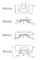
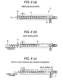
- Fig. 2 shows explanatory views of a process for manufacturing a molded product having a complicated three-dimensional shape by using a method according to the invention.
- two metal molds an upper metal mold and a lower metal mold.
- Fig. 2(a) is a plan view of the forming mold 11 placed on a lower metal mold 21, and Fig. 2 (b) is a front view of the forming mold 11.
- the molten resin is coated one time in an arrow mark 22 direction shown in Fig. 2 (a) using a discharge port having a large width.
- a stamper 23 having a minute uneven portion on the surface thereof is used as part of the forming mold 11. This stamper 23 is placed on the projecting portion 211 of the lower metal mold 21.
- the forming mold 11 and stamper 23 are heated.
- Fig. 2(a) is a plan view of the forming mold 11 placed on a lower metal mold 21
- Fig. 2 (b) is a front view of the forming mold 11.
- the molten resin is coated one time in an arrow mark 22 direction shown in Fig. 2 (a) using a discharge port having a large width.
- a stamper 23 having a minute uneven portion on the surface thereof is used as part of the
- thermoplastic resin 12 is coated in shape and thickness which are almost similar to those of a final shape of the molded product (resin coating step).
- an upper metal mold 24 is moved downward to press the coated thermoplastic resin and arrange the shape of a molded product (compressing step).
- Fig. 2(d) with the pressing force left applied, the thermoplastic resin is cooled and solidified (solidifying step). Then, the forming mold is opened and the molded product 25 is removed from the forming mold.
- a specially preferred method according to the invention may include a series of the following steps (a) to (i):
- the "temperature where the molten resin 12 to be discharged in the resin coating step is able to adhere to the inside of the minute uneven portion or to the cavity surface having a minute uneven portion” can be determined according to the conditions of the surface of the forming mold 11 (such as the surface roughness), the mother material of the forming mold 11 (such as the presence or absence of a treatment using a mold release agent), the kinds and temperature of the molten resin, the moving speed (resin coating speed) of the resin coating device, and the like.
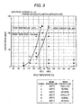
- Fig. 3 is an explanatory view to show how to determine the temperature of the cavity surface of the lower metal mold.
- a polymethyl methacrylate manufactured by Kuraray Co., Ltd. (Parapet GH1000S) is coated on a surface of a cavity made of stainless steel (SUS304) and finished with surface roughness of 1.6S while varying the resin temperature, cavity temperature and coating speed, thereby finding out the conditions that can achieve good resin coating.
- no mold releasing treatment is executed on the cavity surface at all.
- the temperature of the metal mold cavity may be set at a temperature of about 145°C or higher; and also, when the resin temperature is set for 250°C, the cavity temperature may be set at a temperature of 130°C or higher.
- the mold manufacturing method of the invention is very advantageous in that it can manufacture the molded product at a low cost.
- the raising of the temperature of the cavity of the upper metal mold may be completed before the forming mold is closed in the compressing step and the cavity is contacted with the upper surface of the coated molten resin. Therefore, the raising of the temperature of the upper metal mold may also be started, for example, during the resin coating step. The raising of the temperature of the cavity of the lower metal mold may be completed before the molten thermoplastic resin is contacted with the forming mold in the resin coating step.
- the molten resin has a given level of viscosity (for example, 1000 Pa.s or more) even when it is in a melted state. Therefore, the molten resin 12 can be coated until the coated molten resin has substantially the same shape as the final shape of the molded product.
- the discharge port 13 is moved once for coating the molten resin once in the arrow mark 22 direction using a wide discharge port.
- the invention is not limited to this.
- the molten resin may also be coated while reciprocating the discharge port 13 two or more times.
- the resin coating device having the discharge port 13 may be set so as to be able to move up to the six degrees of freedom, whereby, even when the forming mold 11 has a further complicated shape such as a three-dimensional shape, the discharge port 13 is able to follow the shape of the forming mold 11.
- supply of the molten resin to the resin coating device may be completed before the resin coating is executed.
- such molten resin supply may be executed in the step where the resin coating device is not in operation such as in the resin solidifying step or in the mold unfastening step. In this case, the molten resin can be coated immediately after completion of the metal mold temperature raising step. Therefore, the time (the cycle time) necessary for the molding operation can be reduced.
- the pressing pressure can be set for 10 MPa or less.
- the reason for this is as follows: that is, since the molten resin is coated in a shape substantially the same as the final shape of the molded product, there is no need to deform and move the coated molten resin by applying a high pressing force; and also, since the molten resin during compression is soft, the shape of the minute uneven portion can be transcribed to the molten resin with a very low pressing force. Therefore, even when the pressing force generating device is small, a product of a large area can be manufactured. This leads to the size reduction, space saving, energy saving and cost reduction of the molded product manufacturing apparatus.
- the molded product manufacturing method of the invention can provide a molded product which not only has excellent optical characteristics such as low residual stress, low birefringence and high optical-transparency, but also has high dimensional accuracy free from a bend.
- the minute uneven portion 10 of the forming mold 11 is hard to destroy, which leads to the extended life of the forming mold 11. Still further, since a powerful pressing force is not necessary, a forming mold made of zinc selenide (ZnSe) or silicon (Si) having no tolerance against pressure can be used. These materials are infrared ray transmission materials. Therefore, when these materials are used as the cavity surface and infrared rays are radiated onto the thermoplastic resin through such cavity surface as disclosed in Japanese Patent No. 3169786 , the temperature reduction of the thermoplastic resin can be restricted and thus the transcribe of the shape of the minute uneven portion can be attained with more accuracy.
- ZnSe zinc selenide
- Si silicon
- the shape of the molded product can be arranged with further reduced pressure.
- the heating plate may be a plate on which an infrared lamp such as a halogen lamp mounted, or a plate which is heated by an ordinary heat transfer heater (this plate can heat the molten resin through the transfer of radiant heat from the plate).
- the upper metal mold may be temporarily stopped just before the cavity surface of the upper metal mold is contacted with the resin, waiting for a rise in the temperature of the top surface of the resin due to the radiant heat from the cavity surface of the upper metal mold, and the molten resin may be pressed when the temperature of the molten resin top surface rises up to a desired temperature.
- the heating means since radiant heat is used, the heat transfer is approved even in the vacuum. Therefore, even when the below-mentioned pressure reducing/evacuating step is carried out, the heating of the molten resin can be achieved efficiently.
- a precision pressing force generating device which is capable of not only opening and closing a metal mold by moving one of the upper and lower metal molds but also mold fastening and pressing the resin, can be realized by a vertical pressing machine or the like.
- the pressure reducing/evacuating step it is preferable to provide a function to detect the position of the forming mold accurately and stop temporarily the mold closing operation in a state where a minute clearance intervenes between the upper metal mold cavity surface and the molten resin top surface.
- the solidifying step it is preferable to close the forming mold by an amount corresponding to the volume shrinkage of the molded product (that is, high-precision pressing force control may be made) while allowing the pressing force to follow the set value with high accuracy in order to compensate the volume shrinkage of the molded product.
- the below-mentioned mold unfastening step it is necessary to open the forming mold slightly only by a stroke smaller than the thickness of the molded product.
- a pressing force generating device which, as a drive system, uses a mechanism easy to achieve a precise control such as a servo motor.
- the air in the minute clearance may be sucked to thereby provide a pressure reduced state or a substantially vacuum state and, after then, the cavity surface of the upper metal mold 24 and the top surface of the thermoplastic resin may be contacted with each other and the pressing force may be then applied to the resin.
- This can remove the air intervening between the molten thermoplastic resin and the cavity of the upper metal mold 24, which can in turn avoid poor transcription possibly caused by the air trapped and confined in such minute clearance.
- the air suction port may be formed specially in the cavity surface.
- a forming mold including a mechanical ejector for example, the air can be sucked from a clearance in the cavity formed due to the sliding motion of the ejector.
- a well-known vacuum pump or the like may be used as the sucking means.
- the present pressure reducing/evacuating step can be executed with more efficiency in a forming mold composed of upper and lower metal molds and structured such that the cavities of the upper and lower metal molds have male and female shapes and, when the upper and lower metal molds are fitted with each other in the mold closing step, the male side cavity is inserted into the female side cavity by a slight amount to thereby form a closed space.
- the timing for pressure reducing and providing a substantially vacuum state may preferably be set in the time when, after formation of the closed space, a minute clearance intervenes between the cavity surface of the upper metal mold and the top surface of the molten resin.
- the reason for this is that, after the cavity surface and molten resin are contacted with each other and the air is confined between them, the effect of the air suction cannot be obtained if no suction port formed in the air closed range.
- the suction means may be started when the forming mold reaches a desired position, and the suction means may be stopped at a position where the cavity surface of the upper metal mold is perfectly contacted with the top surface of the molten resin.
- start of the suction means ⁇ stop of the mold closing operation ⁇ suction of the air for a given time under control using a timer ⁇ resumption of the mold closing operation.
- means for detecting the pressure in the cavity After the air is sucked, at a time when the pressure of the cavity is reduced down to a desired pressure, the mold closing operation may be resumed.
- the amount of opening of the forming mold may be larger than the height or depth of the minute uneven portion.
- the installed releasing device on the forming mold there can be used a mechanical ejector or an air blow mechanism respectively embedded in the forming mold.
- the entire surface of the molded product can be released from the cavity surface by using such releasing device.
- a minute releasing portion is formed between the molded product and cavity surface by the pressing force of the mechanical ejector or by a discharge pressure to be applied to fluid discharged from a fluid discharge port, the fluid enters the releasing portion. Then, the discharge pressure propagates to promote the next releasing, thereby the releasing portion is gradually expanded. This phenomenon occurs successively, with the result that the entire surface of the molded product is released from the cavity surface.
- the well-known air blow mechanism that is, a mechanism in which a discharge port for discharging the fluid such as the air is formed in the cavity surface (preferably, in the center of the molded product), and the fluid is discharged from the discharge port.
- the mechanical ejector system because the mechanical ejector can push (apply an exfoliative force) only a local portion of the surface of the molded product, there is raised a problem that, if the molded product becomes thin in the thickness, the molded product can be broken or destroyed before the surface of the molded product is released from the cavity surface.
- the pressing force can be applied to the whole of the releasing portion to thereby generate the releasing force uniformly. Accordingly, it is easy to release a thin wall molded product.
- the forming mold is opened to such a distance that the molded product can be removed therefrom, and the molded product is then removed from the forming mold.
- thermoplastic resin to be used in the invention is not limited to specific resin but there can be used various kinds of resin.
- thermoplastic resin that is produced specially so as to match the desired performance of a molded product.
- thermoplastic resin there can be added various kinds of well-known additives as the need arises.
- various fillers such as glass fibers or carbon, heat resisting stabilizers, weatherproof stabilizers, antistatic agents, slip agents, anti-blocking agents, anti-misting agents, lubricants, dyes, pigments, natural oil, synthetic oil, wax, or the like, can be added.
- a molded product manufacturing method of the invention there can be obtained a molded product which has a small thickness in the range of 50 ⁇ m to 5 mm and a large area with a side length of the molded product exceeding 1000 times the thickness of the molded product.
- a molded product manufacturing apparatus is characterized in that it comprises a forming mold which includes a minute uneven portion on a surface thereof; heating means which heats the forming mold; cooling means which cools the forming mold; and a resin coating device which fills a molten thermoplastic resin into the minute uneven portion, wherein the resin coating device includes: a plasticizing part which plasticizes a thermoplastic resin; a resin reserving part which reserves the plasticized molten resin therein; and a discharge port which discharges the molten thermoplastic resin therefrom, and wherein the resin coating device is movable in such a manner that the molten thermoplastic resin is discharged onto the minute uneven portion from above.
- the forming mold including a minute uneven portion on the surface thereof may be set in any portion of the cavities of the upper and lower metal molds so as to match the required performance of the molded product, as described above.
- it may be set in the cavity surface of the lower metal mold onto which the molten resin is precision coated by the resin coating device, whereby the shape of the minute uneven portion can be transcribed under low pressure and with high accuracy.
- a minute uneven portion may be engraved on the surface of a stamper using a semiconductor process such as a photolithography method, an electroplating method, and an ion etching method, and the formed minute uneven portion may be set within a forming mold.
- the material of the stamper there can be used nickel (or a nickel alloy), silicone, glass, or the like.
- the stamper may be made of only such material.
- a minute uneven portion made of a nickel or the like on a plate-shaped mother member (a silicone base plate) having a thickness of, for example, several tens ⁇ m to several mm.
- a minute uneven portion may also be formed directly on the cavity surface of the main body of the forming mold.
- the section shape of the uneven portion is basically rectangular but it may also be tapered (trapezoidal), triangular, semi-circular, or semi-elliptic.
- heating means for example, there are available the following methods.
- heating means 53 such as an infrared lamp may be provided in the vicinity of the discharge port 52 of a resin coating device 51, and the molten resin may be coated while locally heating the surface of the cavity 54 just before the molten resin is coated so as to raise the temperature of the cavity 54 surface up to a temperature where the molten resin is able to adhere to the cavity 54 surface.
- the moving direction of the resin coating device is a direction shown by the arrow mark 55
- a reference numeral 56 designates the portion that is heated locally by the heating means 53 such as an infrared lamp
- a reference numeral 57 stands for the coated molten resin.
- heating and cooling means may be used in proper combination according to cases.
- the plasticizing part may have a function to be able to plasticize resin into melted state and a function to be able to supply the thus molten resin to the resin reserving part of the resin coating device.
- the plasticizing part for example, there may also be used a single screw extruder or a twin screw extruder.
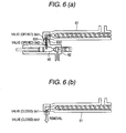
- a resin coating device may also be structured such that, as shown in Fig. 6(a), a mounting and removing mechanisms 631 and 632 are provided in both of a plasticizing part 61 and a resin coating device 62, respectively; the plasticizing part 61 is structured to be mountable onto and removable from the resin coating device 62; valves 641 and 642 capable of opening and closing their associated resin flow passages are provided in both of the plasticizing part 61 and resin coating device 62, respectively; in a state where the plasticizing part 61 and resin coating device 62 are connected together, both valves are opened to thereby allow the flow passages for molten resin to communicate with each other; the molten resin is fed from the plasticizing part 61 into the resin reserving part 65 of the resin coating device 62; and, at the time when a given amount of molten resin is reserved, the valves 641 and 642 are respectively closed and the plasticizing part 61 is removed as shown in Fig.
- Fig. 7 there may be employed a structure as shown in Fig. 7: that is, the plasticizing part 61 and resin coating device 62 are connected together by a flexible flow passage 66 and thus the molten resin can be fed into the resin coating device 62 from the plasticizing part 61.
- an inline-type injection molding machine 71 includes a resin reserving part 72 and a screw 73 which can be rotated and can be moved in the forward and backward directions.
- the screw 73 is rotated in the arrow mark 74 direction, the screw 73 moves in the backward direction and a resin is plasticized while moving in the arrow mark 75 direction.
- the molten resin reserved within the resin reserving part 72 is discharged from a discharge port 77.
- the resin coating device may be composed of a plasticizing cylinder 82 including a screw 81 and an injection cylinder 84 including a piston 83 movable in the forward and backward directions.
- molten resin plasticized in the plasticizing cylinder 82 may be fed to and reserved in the leading end portion of the injection cylinder 84.
- the piston 83 may be moved forward so as to discharge the molten resin from a discharge port 85.
- reference numeral 86 designates a valve, and the molten resin can be discharged from the discharge port 85 by opening the valve 86.
- molten resin transport means such as a screw or a piston may be provided in a reactive pot or a reactor 87, and the may introduce the plasticized resin into the cylinder 89 of the above-mentioned injection molding machine after the resin is plasticized within the reactor 87.
- the temperature for plasticizing the resin may be a temperature where the resin material can be melted.
- a structure which is mainly composed of a plasticizing part 61 for melting and transporting a thermoplastic resin, a resin reserving part 65 connected to the plasticizing part 61 for injecting a poured molten resin (the detailed structure of which will be discussed later) in a predetermined feed rate, and a discharge part 212 for discharging the molten resin fed out from the resin reserving part 65 onto a discharged resin receiving surface from above.
- the resin reserving part 65 may preferably be composed of a reserving cylinder which reserves once therein the poured molten resin and injects the molten resin in the predetermined feed rate.
- Fig. 12 is an explanatory schematic sectional view of a reserving cylinder used in the present invention.
- a reserving cylinder 210 comprises a cylinder 1101 having a cylindrical shape as a whole for reserving the molten resin therein, a piston 1102 provided within the cylinder 1101 for push and inject the molten resin in the predetermined feed rate, and piston drive means 1103 for moving the piston 1102 back and forth. Also, the reserving cylinder 210 further includes, in the outer peripheral portion thereof, means for heating and cooling the surface of the storing cylinder. As shown in Fig. 12, a clearance part 1104 through which the molten resin can pass is formed between the cylinder 11010 and piston 1102.
- the molten resin flows from the plasticizing part 61 through an entrance port 1105, the molten resin is allowed to flow through the clearance part 1104 in the arrow mark direction.
- the size of the clearance part 1104 maybe determined properly depending on the kinds of molten resin used, for example, it may be several mm or so, and, specifically, it may be in the range of 0.5 to 5 mm.
- the piston drive means 1103 is put to work so as to move the piston 1102 backward as shown in Fig. 13. Owing to this operation, the molten resin is gradually reserved in the cylinder 1101 starting from the leading end portion (discharge port side) of the cylinder 1101.
- the piston drive means 1103 is operated to move the piston 1102 forward by a given distance, thereby being able to send out the molten resin at a predetermined feed rate.
- the position control of the piston 1102 must be made with relatively high accuracy. Therefore, as the piston drive means 1108, there may be used a pressing force generating device such as a servo motor having a mechanism easy to secure accuracy.
- the molten resin which has flowed in first, is first fed and discharged out to the discharge part.
- the resin melting part and reserving cylinder 210 are connected together by a short path, the residence time of the molten resin can be reduced, thereby being able to prevent the occurrence of the thermal degradation of the molten resin more effectively.
- a molded product is manufactured using the thermally degraded molten resin, there may be raised a problem that a desired optical transmittance or a desired refraction coefficient cannot be obtained when the molded product is used in an optical product.
- a back flow preventive part 1106 which prevents the molten resin from flowing therethrough in order to prevent the molten resin, which has first flown into the cylinder 1101, from flowing into the opposite direction (toward the piston drive means 1103 side) to the leading end portion of the cylinder 1101.
- the back flow preventive part 1106 has a curved surface extending from the entrance port 1105 of the molten resin in the direction of the leading end portion of the cylinder 1101 such that the molten resin can be easily guided to the leading end portion of the cylinder 1101.
- a valve which is capable to open and close the connecting flow passage, is provided in the connecting flow passage between the plasticizing part 61 and reserving cylinder 210.
- Fig. 14 is a schematic sectional view of a molded product manufacturing apparatus, explaining a structure in which a valve is located in a connecting flow passage formed between the plasticizing part 61 and reserving cylinder 210.
- the molded product manufacturing apparatus shown in Fig. 14 is almost similar in structure to the molded product manufacturing apparatus shown in Fig. 11. However, it is different from the manufacturing apparatus shown in Fig. 11 in that a valve 215 is located in a connecting flow passage 214 between the plasticizing part 61 and reserving cylinder 61.
- the piston drive means 1103 is operated to move the piston 1102 forward by a given distance so as to inject the molten resin into the discharge part 212 in the predetermined feed rate.
- the injecting amount of the molten resin is determined by the volume of the molded product. Therefore, in order to manufacture the molded product with high precision, it is necessary to reserve a controlled amount of the molten resin into the cylinder 1101 and also inject the controlled amount of the molten resin from the cylinder 1101.
- the molten resin within the plasticizing part 61 is allowed to flow into the cylinder 1101 more than necessary and thus the amount of the molten resin flowing into the cylinder 1101 exceeds the predetermined amount. In such case, the excessive amount of the molten resin is reserved in the cylinder 1101, which makes it difficult to manufacture the molded product with high precision.
- the valve 215 is located in the connecting flow passage 214 between the plasticizing part 61 and reserving cylinder 210, and the valve is closed to thereby cut off the flow of the molten resin from the plasticizing part 61 into the cylinder 1101 at the time when the reserve of the molten resin into the cylinder 1101 is completed. This makes it possible to reserve a predetermined amount of the molten resin.
- the piston drive means 1103 is operated to move the piston 1102 forward by a given distance to thereby inject the molten resin into the discharge part 212 in the predetermined feed rate.
- the valve 215 may be left closed. By leaving the valve 215 closed, the injecting pressure of the molten resin due to the forward movement of the piston 1102 can be prevented from escaping to the plasticizing part 61 through the connecting flow passage 214. This makes it possible to inject the molten resin to the discharge part 212 in the predetermined feed rate. Accordingly, the molded product can be manufactured with high precision.
- valve 215 there can be used any type of valve, provided that it can cut off the flow passage (connecting flow passage 214) of the molten resin and can control the inflow and outflow of the molten resin.
- a well-known rotary valve can be used.
- the discharge part 212 for discharging the molten resin fed out from the plasticizing part 61 onto the discharged surface from above is not limited to a specific discharge part.
- a discharge part that can deform the molten resin into a sheet (membrane) shape with high precision before it is discharged.
- the discharge part 212 is directly connected with the resin reserving part 65.
- the plasticizing part 61 as an example of the plasticizing part 61, description has been given of the reserving cylinder 210 structured such that it once reserves the molten resin having flown therein and then injects the thus reserved molten resin in the predetermined feed rate.
- the invention is not limited to this.
- the plasticizing part 61 instead of the reserving cylinder 210, there can be used a cylinder having an injection function.
- Fig. 15 is an explanatory schematic sectional view of another embodiment of a molded product manufacturing apparatus according to the invention which uses a cylinder having an injection function as a resin injecting part.
- the molded product manufacturing apparatus shown in Fig. 15, similarly to Fig. 11, is mainly composed of a plasticizing part 61 for melting a thermoplastic resin and transporting the molten resin, a resin reserving part 65 connected to the plasticizing part 61 for injecting the molten resin poured therein and a discharge part 212 for discharging the molten resin fed out from the resin reserving part 65 onto a discharged resin receiving surface from above.
- the resin reserving part there is used a cylinder 211 having an injection function.
- the cylinder 211 there can be used a cylinder which is produced for an injection molding machine; for example, a cylinder the whole of which has a cylindrical shape and also which includes a penetration inner hole 1112 with a screw 1111 contacted with the inner surface thereof. Also, the cylinder 211 further includes two or more heaters which are respectively mounted on the outer peripheral surface thereof.
- the screw 1111 is structured such that it can be rotated as well as can be moved back and forth by drive means 1113.
- the molten resin from the plasticizing part 61 flows into the cylinder 211 from an entrance port 1114.
- the molten resin is then fed in the direction of the leading end portion of the cylinder 211 owing to the rotation of the screw 1111.
- the screw 1111 is moved forward according to a normally used method to thereby inject the molten resin to the discharge part 212 in the predetermined feed rate.
- valve 215 in a connecting flow passage 214 between the plasticizing part 61 and cylinder 211, and close the valve 215 when the reserve of the molten resin into the cylinder 211 is completed so as to cut off the flow of the molten resin from the resin reserving part.
- This provides an effect that the reserve of the molten resin in the predetermined feed rate is possible.
- the molten resin is fed out to the discharge part 212 by the injection function of the cylinder 211 in the predetermined feed rate.
- the valve 215 may be left closed at this time as well.
- the molded product can be manufactured with high precision.
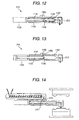
- Fig. 16 is an explanatory view of an example of such resin coating device.
- a resin coating device A1 is generally composed of a cylinder 91 functioning as a resin reserving part, and a resin coating part 92 which belongs to the cylinder 91 and is formed substantially integral with the cylinder 91.
- a piston 94 which can be driven in a vertical direction in Fig. 16 by a piston drive device 93.
- the piston 94 is driven downward, the molten resin is pushed out through the resin coating part 92 to a forming mold.
- a resin supply passage 95 is opened up.
- a rotary valve 96 which is an example of means for opening and closing the resin supply passage 95.
- the above-mentioned plasticizing part for melting solid-state resin is provided in the present resin coating device A1, and the plasticized molten resin can be supplied through the rotary valve 96 to the cylinder 91.
- the push-out amount of the molten resin in the cylinder 91 is controlled very carefully depending on the drive speed of the piston 94.
- the lower end portion of the cylinder 91 is narrowed in a tapered manner to provide a resin passage 99 which is continuous with the resin coating part 92.
- the resin coating part 92 is composed of a resin adjusting portion 100 for allowing the molten resin to flow therethrough or for reserving the molten resin temporarily therein and a spatula portion 101 which is situated at the lower end of the resin adjusting portion 100.
- the lower end portion of the spatula portion 101 is cut off obliquely and can be thereby moved at a given speed in the arrow mark D direction. Since the inclined surface 102 of the spatula portion 101 is situated ahead in a moving direction, a discharge port 103 which functions as the exit of the molten resin is opened up in the inclined surface 102.
- the discharge port 103 is in communication with the resin adjusting portion 100.
- a needle 104 the leading end portion of which is reduced in diameter in a tapered manner.
- the upper end portion of the needle 104 is connected to the output shaft of a needle drive device 105 and is sealed by packing glands 106, 106.
- the needle 104 is driven downward properly by the needle drive device 105, degrees of opening of the discharge port 103 can be adjusted.
- a heater 107 which functions as heat generating means. The amount of heat to be generated by the heater 107 is also controlled in the above-mentioned manner.
- the control unit 98 also includes setting means 108 for setting the temperatures and pressures of the molten resin within the cylinder 91 and resin coating part 92, the driving speed of the piston 94, the degrees of opening of the discharge port 103, the moving speed of the resin coating device A1 in the resin coating operation thereof, and the like.
- the control unit 98 which has the above-mentioned function and includes the setting means 108, is connected by a signal line a to a resin pressure sensor 109 for measuring the pressure of the molten resin within the cylinder 91, is connected by a signal line b to a temperature sensor 110 composed of a thermocouple and the like for detecting the temperature of the molten resin, and is connected by a signal line c to a speed sensor 111 for detecting the driving speed of the piston 94, respectively.
- control unit 98 is also connected to a needle position detect sensor 112 by a signal line d.
- Various kinds of measurement values measured by these sensors 109 to 112 are respectively input to the control unit 98 through their associated signal lines a to d, and are operated by the control unit 98.
- the manipulated value of the control unit 98 are respectively applied to the heaters 97, 97, ... 107 through a power line h, to the piston drive device 93 through a power line i, and similarly to the needle drive device 105 through a power line j.
- the temperatures of the heaters 97, 97, ... 107, the driving speed of the piston 94, the pressure of the molten resin, the opening degrees of the discharge port 103 and the like are set in the control unit 98 by the setting means.
- the rotary valve 96 is opened and the plasticized resin is supplied to the cylinder 91.
- a resin coating operation is started.
- the piston 94 is driven, whereby the molten resin in the cylinder 91 maintained at a set temperature is fed to the resin adjusting portion 100 of the resin coating part 92 by a given amount.
- the molten resin is then pushed up onto the forming mold by the needle 104 from the discharge port 103 kept at a given opening degree. Simultaneously with this, the spatula portion of the resin coating device A1 is moved in an arrow mark D direction. The thus pushed-out molten resin is extended onto the forming mold by the spatula portion 101. This completes the resin coating operation.
- the discharge amount of the resin from the discharge port is controlled according to the coating width, coating thickness and coating speed of the molten resin (the speed at which the discharge port of the resin coating device moves on the forming mold) to the forming mold.
- the discharge port preferably, may have such a shape that the molten resin can be discharged in a slit manner in a direction substantially perpendicular to the resin coating direction.
- the discharge port is composed of one or more discharge ports which are connected together in a direction substantially perpendicular to the resin coating direction.
- the widths and shapes of the respective discharge ports may be changed freely according to the shapes of the forming molds.
- the number of discharge ports connected may be changed to thereby change the discharge width.
- a gate 120 for changing the discharge width and the resin may be coated while changing the position of the gate 120 successively so as to provide a desired resin coated shape.
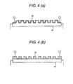
- the discharge port spatula portion may have such a shape that a pouring gate in the obliquely cut-off lower end portion thereof is provided on the rear side in the resin coating advancing direction as shown in Fig. 18(a), or may have such a shape that two pouring gates are provided on both back and front sides in the resin coating advancing direction as shown in Fig. 18 (b).
- the discharge port spatula may also have such a shape that the leading end portion of the discharge port is formed in a tapered manner as shown in Fig. 18(c).
- pouring gates in the discharge port on the right and left sides as well in the advancing direction, whereby four pouring gates may be provided respectively on the right and left sides as well as on the back and front sides in the discharge ports.
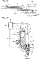
- Fig. 19 is an explanatory view of an embodiment of the whole structure of a molded product manufacturing apparatus according to the invention.
- a resin coating device 131 is structured such that a plasticizing part 132 is released from the resin coating device 131, a flexible flow passage 133 connects the resin coating device 131 and the plasticizing part 132, and the molten resin is fed to the to the resin coating device 131 from the plasticizing part 132 through the connecting flow passage 133 (see Fig. 7).
- a table 134 movable in the X axis direction (in the translating direction) and a drive motor 135 for driving the table 134
- a table 136 movable in the Y axis direction and a drive motor 137 for driving the table 136
- a table 138 movable in the Z axis direction and a drive motor 139 for driving the table 138.
- a stamper 140 including a minute uneven portion on the surface thereof, while the stamper 140 is placed on a lower metal mold 141.
- This lower metal mold 141 and an upper metal mold 142 are respectively mounted on a precision vertical digital pressing machine 143, while each of them includes metal mold heating means 144 composed of an electric heater and metal mold cooling means composed of temperature controlled water. Also, means for releasing a molded product from the mold is composed of a well-known mechanical ejector or air blower using mold releasing means drive device 146.
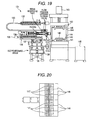
- the resin coating device 131 includes six-divided discharge ports 147 as shown in Fig. 20. The discharge quantities of the respective discharge ports 147 can be further adjusted by their associated flow passage opening/closing valve driving cylinders 148 (in Fig. 19, they are shown by the arrow mark XV).
- control of the temperature of the flexible flow passage the control of the temperatures of the cylinder and discharge ports of the resin coating device, the control of the temperatures of the upper and lower metal molds, the opening and closing control of the valves for opening and closing the flexible flow passage and the resin flow passage of the resin coating device, the opening and closing control of the valves for opening and closing the multiple divided discharge ports, the control of the operation for moving the XYZ axes tables and pistons of the resin coating device at desired positions and speed, the control of the mold opening and closing operation (the position, speed and pressure) of the digital pressing machine, and similar control are respectively executed by a control unit (not shown).
- the resin coating device according to the embodiment shown in Fig. 19 is mounted on the XYZ table and has a cantilevered structure that the rear side of the resin coating device is fastened to a stage.
- the discharge part 212 of the resin coating device may be moved while it is being supported by a highly rigid guide and may discharge the molten resin.
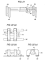
- Fig. 21 is an explanatory view of a step of discharging the molten resin from the discharge part 212 to be moved while it is being supported by a highly rigid guide.
- the two sides of the discharge part 212 are supported by at least two highly rigid guides 291, 292 which are respectively provided along the coating direction of the molten resin.
- the highly rigid guides 291, 292 are respectively fixed by two or more support members 293, 294 which are respectively located on the upstream and downstream sides in the coating direction of the molten resin.
- the highly rigid guides 291, 292 may be made of any material, provided that it can prevent the discharge part 212 from being flexed in the vertical direction due to the reaction against the discharge of the molten resin.
- they may be made of stainless steel.
- a method for supporting the discharge part 212 besides the method for supporting the discharge part 212 by at least two highly rigid guides 291, 292 shown in Fig. 21, there can also be employed such a method as shown in Fig. 22 in which the discharge part 212 is supported by two guide rails.
- the discharge part 212 may be supported by at least one guide rail using a guide rail having a wide width. Specifically, the discharge part 212 is moved while it is being supported by two highly rigid guides (guide rails) 291 and 292 using a linear guide bearing.
- guide rails guide rails
- the discharge part 212 is supported by two highly rigid guides 291 and 292 respectively located along the coating direction of the molten resin through support members 293 and 294, and the highly rigid guides 291 and 292 are respectively fixed to the main body of the molded product manufacturing apparatus on which the resin coating device is mounted.
- Fig. 22 (a) is a top plan view of the resin coating device
- Fig. 22 (b) is a front view of the resin coating device
- Fig. 22(c) is a side view of the resin coating device.
- a method for fixing the highly rigid guides there can be used any method. For example, a method for fastening (screwing) the highly rigid guides to a bed, which is provided in the apparatus main body, can be used.
- the lower metal mold 141 includes a projecting portion, and the stamper 140, which includes a minute uneven portion, is mounted on the surface of the projecting portion.
- moving means for moving the lower metal mold 141 in a vertical direction and the distance between the leading end lip portion 284 of the discharge part 212 and stamper 140 may be adjusted.
- a role for the vertical movement is played by the forming mold.
- the moving speed of the discharge part 212 can be enhanced, thereby being able to improve the productivity of the present molded product manufacturing apparatus.
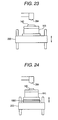
- a method as shown in Fig. 23 there can be employed such a method as shown in Fig. 23.
- the lower metal mold 141 is set in such a manner as shown in Fig. 23.
- a platen of a pressing machine 200 having the pressurizing function of a pair of upper and lower metal molds is used as moving means. By moving the platen 200 in the vertical direction, the distance between the leading end lip portion 284 of the discharge part 212 and stamper 140 can be adjusted.
- a method as shown in Fig. 24 there can also be employed such a method as shown in Fig. 24.
- a platen of a pressing machine 200 functioning as moving means and a lower metal mold 141 there is interposed a vertically movable stage 1001, and a distance between the leading end lip portion 284 of the die and stamper 140 can be adjusted by moving the vertically movable stage 1001 in the vertical direction.
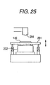
- a lower metal mold 232 and a forming mold 281 are structured such that they can be released from each other, only the forming mold 281 can be moved in the vertical direction, and the distance between the leading end lip portion 284 of the discharge part 212 and stamper 140 can be adjusted by moving the forming mold in the vertical direction.
- the molten resin can be discharged onto the stamper 140 in a three-dimensional geometry, and the coating thickness of the molten resin to the stamper 140 can be changed easily.
- a molded product which has the precise microstructure and also which has high dimensional precision, low residual stress, low birefringence, high optical-transparency and excellent mechanical strength, can be provided in a three dimensional geometry, thin wall and large-area according to a very low molding pressure molding process.
- the present molded product can be used suitably in various industrial products, for example: (a) key parts in the electronic display field such as micro-lens array, a light guide plate for liquid crystal display, a flexible display substrate, a wave plate, a reflecting plate, a phase difference plate, a free curved- surface mirror, an LED light emitting panel, a Fresnel lens, and the like; (b) key parts in the optical information communication field such as a flexible polymer optical waveguide, a free curved-surface diffraction grating, a two-dimensional image sensor array, a pickup lens, a hologram, a flexible waveguide type illuminating plate; (c) key parts in the optical recording medium field such as an up-coming-generation DVD (a blue ray disk), a cover layer for a blue ray disk, a DVD, an ultra-thin IC card and the like; (d) key parts in the life science field such as an integrated chemical chip, a DNA chip, a bio-chip, a protein chip
- a molded product is manufactured using the following molded product manufacturing apparatus.
- Discharge port shape length 30 mm x width 1 mm. A shape shown in Fig. 18(c).
- Extruding and pressurizing mechanism piston.
- Piston diameter ⁇ 10 mm.
- Resin heating means an electric heater wound around the outer periphery of a cylinder.
- a discharge part uses a plate-shaped electric heater.
- Cavity area 30 mm x 50 mm.
- the edge portion of the metal mold has a step.
- Heating source a built-in cartridge heater.
- Cooling source temperature controlled water is made to flow through a medium flow hole. [Press] Maximum clamping force: 10t.
- the stamper has a rectangular shape the length of which is 30 mm and the width of which is 50 mm, and also the stamper has a thickness of 0.3 mm.
- the stamper was set on the cavity surface of the forming mold. However, the stamper has a step on the edge portion thereof. In this case, there was obtained a molded product having a shape which faithfully follows the shapes of the stamper and metal mold cavity.
- polymethyl methacrylate is molded according to an injection molding method, it is generally said that, when a value obtained by dividing the flow length (the longitudinal-direction distance of the molded product) by the thickness exceeds 130, it is difficult to mold the polymethyl methacrylate.
- a molded product difficult to be molded according to the injection molding method could be obtained with a low pressure equal to or less than 80 kg/cm 2 .
- Minute uneven shape Y-shaped minute flow passage having a section surface of a width 50 ⁇ m x a height 50 ⁇ m.
- Stamper shape It has a rectangular shape of a length 30 mm and a width 50 mm and also it has a thickness 0.3 mm (it includes the above-mentioned minute uneven shape).
- the coating thickness of the resin coated onto the stamper set in the central portion of the cavity was set for 250 ⁇ m.
- the enlarged picture of the terminal end portion of the Y-shaped flow passage shows that there was formed a flow passage having a clear edge, and also that the shape transcribe condition was also good.
- a molded product was manufactured using the molded product manufacturing apparatus shown in Fig. 19.
- the plasticizing part 132 there was used a single screw extruder, and the above-mentioned polymethyl methacrylate was plasticized at a temperature of 250°C.
- the molten resin discharge part of the plasticizing part 132 and the molten resin pouring part of the resin coating device 131 were connected together by the flexible flow passage 133.
- a valve for opening and closing a molten resin flow passage which connects together the flow passage 133 and the resin reserving part of the resin coating device 131.
- the resin coating device 131 includes a resin reserving part (a heating cylinder), a piston functioning as an extruding and pressurizing mechanism, a discharge port 147 shown in Fig. 19 for discharging the molten resin reserved in the resin reserving part, and valves for opening and closing the molten resin flow passages respectively connecting the resin reserving part to the two or more divided discharge ports 147.
- the resin coating device 131 is mounted on a table movable in the translation direction of the XYZ axes and is fastened to a precision vertical digital pressing machine in such a manner that it can be moved in the vertical direction.
- the shape of one of the discharge ports 147 is the shape shown in Fig. 18 (c) which has a length of 50 mm and a width of 1 mm.
- the upper metal mold 142 to be mounted on the digital pressing machine can be heated by the mold heating means 144 composed of an electric heater and also can be cooled by the metal mold cooling means 145 composed of temperature controlled water.
- the mold heating means 144 composed of an electric heater
- the metal mold cooling means 145 composed of temperature controlled water.
- a mechanical ejector and an air blower which use the well-known mold releasing means drive device 146.
- the area of the cavity of the lower metal mold 141 was set for 250 mm ⁇ 250 mm.
- the maximum clamping force of the digital pressing machine is 20t.
- the material used here is the above-mentioned polymethyl methacrylate.
- the manufacturing process of the molded product according to the present embodiment is as follows. Incidentally, the raising of the temperature of the resin coating device, the raising of the temperature of the flexible flow passage that can be heated, and the raising of the temperature of the plasticizing device have been previously completed.
- control systems relating to the respective operations of the plasticizing device, resin coating device, digital pressing machine and the like as well as the setting of a control system relating to the sequence operation for operating them sequentially according to the manufacturing process have also been completed.
- the height of the minute uneven portion is 50 ⁇ m
- a metal mold having a height of about 100 ⁇ m higher than 50 ⁇ m is opened.
- the cavity surface includes a portion which is mirror finished and a portion which is set in the vicinity of the central portion of the cavity surface, in which a mechanical working trace was intentionally left, and on which a stamper was mounted. Further, in the leading end portion of the ejector, there is left a slight mechanical working trace.
- the mechanical working trace intentionally formed in the stamper mounted portion has a minute uneven shape the width and depth of which are respectively about 45 ⁇ m.
- the mechanical working trace of the leading end portion of the ejector has a minute uneven shape the width and depth of which are respectively about 50 ⁇ m.
- This confirmation is also attained similarly in a molded product manufactured according to another method in which the resin is not pressed, but, after completion of a resin coating step, the resin is solidified and the molded product is then released from the forming mold.
- the maximum pressure in the manufacturing process which can be calculated from the maximum pressing force applied in the compressing step, is 24 kg/cm 2 (2.35 MPa).
- the molded product manufacturing method and apparatus according to the invention can provide a molded product to which a required shape has been transcribed accurately with a very low molding pressure.
- molded product manufacturing method and apparatus in which a molded product having precise microstructure, high dimensional precision, low residual stress, low birefringence, high optical-transparency, and excellent mechanical strength can be provided in a three dimensional geometry, thin wall and large-area by a very low molding pressure molding process.
Landscapes
- Engineering & Computer Science (AREA)
- Mechanical Engineering (AREA)
- Robotics (AREA)
- Casting Or Compression Moulding Of Plastics Or The Like (AREA)
- Moulds For Moulding Plastics Or The Like (AREA)
- Shaping Of Tube Ends By Bending Or Straightening (AREA)
Applications Claiming Priority (2)
| Application Number | Priority Date | Filing Date | Title |
|---|---|---|---|
| JP2004239567A JP3857703B2 (ja) | 2004-08-19 | 2004-08-19 | 成形体の製造方法および製造装置 |
| PCT/JP2005/015145 WO2006019160A1 (ja) | 2004-08-19 | 2005-08-19 | 成形体の製造方法および製造装置 |
Publications (3)
| Publication Number | Publication Date |
|---|---|
| EP1785253A1 true EP1785253A1 (de) | 2007-05-16 |
| EP1785253A4 EP1785253A4 (de) | 2010-09-08 |
| EP1785253B1 EP1785253B1 (de) | 2014-10-08 |
Family
ID=35907543
Family Applications (1)
| Application Number | Title | Priority Date | Filing Date |
|---|---|---|---|
| EP05780446.0A Expired - Lifetime EP1785253B1 (de) | 2004-08-19 | 2005-08-19 | Verfahren zur herstellung von formkörpern und vorrichtung dafür |
Country Status (7)
| Country | Link |
|---|---|
| US (1) | US8119054B2 (de) |
| EP (1) | EP1785253B1 (de) |
| JP (1) | JP3857703B2 (de) |
| KR (1) | KR100861145B1 (de) |
| CN (2) | CN101005932B (de) |
| TW (1) | TWI273961B (de) |
| WO (1) | WO2006019160A1 (de) |
Cited By (1)
| Publication number | Priority date | Publication date | Assignee | Title |
|---|---|---|---|---|
| EP2814654B1 (de) | 2012-02-17 | 2020-04-29 | Guangdong Yizumi Precision Machinery Co., Ltd. | SPRITZGIEßCOMPOUNDER, VERRFAHREN UND PROGRAMMPRODUKT |
Families Citing this family (50)
| Publication number | Priority date | Publication date | Assignee | Title |
|---|---|---|---|---|
| CA2646277C (en) | 2006-03-23 | 2016-01-12 | The Penn State Research Foundation | Heart assist device with expandable impeller pump |
| JP2008046469A (ja) * | 2006-08-18 | 2008-02-28 | Nikon Corp | 回折光学素子の製造方法および樹脂吐出装置 |
| KR100800498B1 (ko) | 2006-08-23 | 2008-02-04 | 엘지전자 주식회사 | 몰드, 그 절삭 가공 장치 및 그에 의해 제조되는 전사체 |
| JP4723436B2 (ja) * | 2006-08-28 | 2011-07-13 | 株式会社日本製鋼所 | 溶融樹脂の塗布による成形体の製造装置 |
| JP5188068B2 (ja) * | 2007-01-16 | 2013-04-24 | 南条装備工業株式会社 | 成形装置 |
| JP4444980B2 (ja) * | 2007-04-02 | 2010-03-31 | 株式会社日本製鋼所 | 成形体の成形用金型およびこれを用いる成形体の製造方法 |
| JP4575412B2 (ja) * | 2007-09-27 | 2010-11-04 | 株式会社日本製鋼所 | 樹脂の糸曳切断方法、樹脂の糸曳切断装置及び樹脂の成形方法 |
| KR100925761B1 (ko) * | 2008-03-11 | 2009-11-11 | 삼성전기주식회사 | 인쇄회로기판의 제작 방법 |
| JP4975675B2 (ja) * | 2008-04-04 | 2012-07-11 | 株式会社日本製鋼所 | 成形体の製造方法および製造装置 |
| CN101683763A (zh) * | 2008-09-25 | 2010-03-31 | 鸿富锦精密工业(深圳)有限公司 | 制造具有微结构导光板的模仁及制造方法 |
| JP4944863B2 (ja) * | 2008-10-29 | 2012-06-06 | 株式会社日本製鋼所 | 熱可塑性溶融樹脂の塗布による成形体の製造装置および方法 |
| KR101561486B1 (ko) * | 2009-04-06 | 2015-10-19 | 삼성전자 주식회사 | 평판 디스플레이 패널, 패널의 수리 장치 및 방법 |
| MX340994B (es) * | 2009-05-15 | 2016-08-02 | Glaxosmithkline Llc | Uso de formacion de imagen termica para control de un proceso de fabricacion. |
| US8847061B2 (en) | 2009-06-11 | 2014-09-30 | Energy Focus, Inc. | Method of making solar collector assemblies with optical concentrator encapsulant |
| CN102639310B (zh) * | 2010-03-18 | 2015-02-18 | 三菱重工塑胶科技股份有限公司 | 注射成型方法、成型品的制造方法以及注射成型装置 |
| JP2011194842A (ja) * | 2010-03-23 | 2011-10-06 | Fujifilm Corp | レンズアレイの製造方法及びレンズアレイの製造装置 |
| US8373985B2 (en) | 2010-05-06 | 2013-02-12 | Research In Motion Limited | Molded assembly |
| JP5442540B2 (ja) * | 2010-06-17 | 2014-03-12 | 株式会社日本製鋼所 | 微細構造体の製造方法 |
| CN102310567B (zh) * | 2010-07-09 | 2015-09-30 | 无锡易维模型设计制造有限公司 | 一种光敏固化成型机树脂涂覆系统 |
| CN103313839B (zh) * | 2010-12-22 | 2016-08-10 | 株式会社日本制钢所 | 微细结构体的制造方法 |
| JP5356452B2 (ja) * | 2011-05-30 | 2013-12-04 | 株式会社日本製鋼所 | 溶融微細転写成形方法及び溶融微細転写成形装置 |
| JP5372071B2 (ja) * | 2011-06-02 | 2013-12-18 | 株式会社日本製鋼所 | 微細構造転写成形方法 |
| JP5717593B2 (ja) * | 2011-08-31 | 2015-05-13 | 住友ゴム工業株式会社 | プレフィルドシリンジ用ガスケットの成型金型 |
| JP5910056B2 (ja) * | 2011-12-13 | 2016-04-27 | 富士ゼロックス株式会社 | レンズ製造装置 |
| DE102013008159A1 (de) | 2012-05-14 | 2013-11-14 | Thoratec Corporation | Mantelsystem für Katheterpumpe |
| GB2504176A (en) | 2012-05-14 | 2014-01-22 | Thoratec Corp | Collapsible impeller for catheter pump |
| US9446179B2 (en) | 2012-05-14 | 2016-09-20 | Thoratec Corporation | Distal bearing support |
| US9421311B2 (en) | 2012-07-03 | 2016-08-23 | Thoratec Corporation | Motor assembly for catheter pump |
| US9358329B2 (en) | 2012-07-03 | 2016-06-07 | Thoratec Corporation | Catheter pump |
| EP4186557A1 (de) | 2012-07-03 | 2023-05-31 | Tc1 Llc | Motoranordnung für katheterpumpe |
| EP3834876B1 (de) | 2013-03-13 | 2022-09-14 | Tc1 Llc | Flüssigkeitsbehandlungssystem |
| JP5754749B2 (ja) * | 2013-05-16 | 2015-07-29 | 株式会社日本製鋼所 | 微細構造体成形方法 |
| US10583232B2 (en) | 2014-04-15 | 2020-03-10 | Tc1 Llc | Catheter pump with off-set motor position |
| US10363349B2 (en) | 2014-04-15 | 2019-07-30 | Tc1 Llp | Heart pump providing adjustable outflow |
| DE102014015275A1 (de) * | 2014-10-16 | 2016-04-21 | Giesecke & Devrient Gmbh | Datenträger mit flächiger Lichtquelle |
| JP2016097607A (ja) * | 2014-11-25 | 2016-05-30 | 株式会社日本製鋼所 | 樹脂成形体の成形方法 |
| US11130985B2 (en) * | 2014-11-27 | 2021-09-28 | Hitachi High-Tech Corporation | Spot array substrate, method for producing same, and nucleic acid polymer analysis method and device |
| US9981435B2 (en) * | 2014-12-17 | 2018-05-29 | Novartis Ag | Reusable lens molds and methods of use thereof |
| US20180169907A1 (en) * | 2015-06-25 | 2018-06-21 | Ev Group E. Thallner Gmbh | Method for producing of structures on a substrate surface |
| JP6146930B2 (ja) * | 2015-10-09 | 2017-06-14 | 株式会社日本製鋼所 | Tダイ保持治具 |
| JP6261051B2 (ja) * | 2015-12-15 | 2018-01-17 | 株式会社日本製鋼所 | 樹脂成形金型及び樹脂成形方法 |
| EP3804804A1 (de) | 2016-07-21 | 2021-04-14 | Tc1 Llc | Fluiddichtungen für katheterpumpenmotoranordnung |
| JP6647169B2 (ja) * | 2016-07-27 | 2020-02-14 | 富士フイルム株式会社 | 経皮吸収シートの製造方法 |
| CN108673704B (zh) * | 2018-04-16 | 2021-03-23 | 临泉县强森木业有限公司 | 一种沙发内嵌式复合木板 |
| JP6948301B2 (ja) * | 2018-09-26 | 2021-10-13 | 富士フイルム株式会社 | 経皮吸収シートの製造方法 |
| CN109719975A (zh) * | 2019-02-25 | 2019-05-07 | 河北工业大学 | 一种复合材料板材成型机及其成型工艺 |
| CN111622001A (zh) * | 2020-04-15 | 2020-09-04 | 江苏亚盛金属制品有限公司 | 钢丝绳的pvc涂覆装置及方法 |
| CN113199836B (zh) * | 2021-04-29 | 2023-09-08 | 曹祖铭 | 一种电子产品外壳的制造方法 |
| CN114576251A (zh) * | 2022-03-23 | 2022-06-03 | 深圳数码模汽车技术有限公司 | 一种零件自动化排钉及折弯工艺 |
| CN115313083A (zh) * | 2022-08-15 | 2022-11-08 | 上海英恒电子有限公司 | 一种功率元件的复合铜排 |
Family Cites Families (31)
| Publication number | Priority date | Publication date | Assignee | Title |
|---|---|---|---|---|
| JPS4981962U (de) | 1972-11-08 | 1974-07-16 | ||
| JPS4981962A (de) | 1972-12-13 | 1974-08-07 | ||
| JPS60201911A (ja) * | 1984-03-27 | 1985-10-12 | Dainippon Printing Co Ltd | 合成樹脂成形板の製造法 |
| JPS6147609U (ja) | 1984-09-04 | 1986-03-31 | プラマツク株式会社 | プレス金型への流動状可塑性材料供給装置 |
| JPS61137726A (ja) | 1984-12-08 | 1986-06-25 | Sakurai Kogyosho:Kk | 発泡樹脂容器のシ−ト成形法 |
| JPS61137726U (de) | 1985-02-19 | 1986-08-27 | ||
| US4787722A (en) * | 1986-04-10 | 1988-11-29 | Fresnel Technologies, Inc. | Fresnel lens with aspiteric grooves |
| JPH01150515A (ja) | 1987-12-08 | 1989-06-13 | Hitachi Chem Co Ltd | 光ディスク基板の製造装置 |
| EP0323642A3 (de) * | 1988-01-05 | 1990-11-07 | Chisso Corporation | Geformtes, elektroleitendes Produkt aus thermoplastischem Kunststoff |
| JPH01286390A (ja) | 1988-05-12 | 1989-11-17 | Hitachi Ltd | 多層プリント板の成形方法 |
| US4967933A (en) * | 1989-02-27 | 1990-11-06 | Asymptotic Technologies, Inc. | Method and apparatus for dispensing viscous materials |
| JPH0577268A (ja) * | 1991-09-19 | 1993-03-30 | Ishikawajima Harima Heavy Ind Co Ltd | 樹脂押出方法及び装置 |
| JPH06830A (ja) | 1992-06-22 | 1994-01-11 | Toshiba Corp | モールドシステム |
| CN1069927A (zh) * | 1992-07-07 | 1993-03-17 | 江西第二机床厂 | 一种金属表面涂覆尼龙方法及装置 |
| JPH06114860A (ja) * | 1992-09-30 | 1994-04-26 | Toppan Printing Co Ltd | レンズシートの製造方法 |
| JP3456290B2 (ja) * | 1995-01-31 | 2003-10-14 | オムロン株式会社 | 光学素子の製造方法及び光学素子製造装置 |
| US5961902A (en) * | 1995-03-27 | 1999-10-05 | Araco Kabushiki Kaisha | Manufacturing method for molded multilayer article |
| US6186765B1 (en) * | 1997-03-31 | 2001-02-13 | Toshiba Kikai Kabushiki Kaisha | Apparatus for forming a molded multilayer product |
| DE69812210T2 (de) * | 1997-04-25 | 2003-12-04 | Kuraray Co., Ltd | Durchlicht-Projektionsschirm |
| JP2000039702A (ja) | 1998-04-30 | 2000-02-08 | Ebara Corp | 微細パタ―ンの転写加工方法 |
| JP3229871B2 (ja) | 1999-07-13 | 2001-11-19 | 松下電器産業株式会社 | 微細形状転写方法および光学部品の製造方法 |
| CN1696826A (zh) * | 2000-08-01 | 2005-11-16 | 得克萨斯州大学系统董事会 | 用对激活光透明的模板在衬底上形成图案的方法及半导体器件 |
| JP3922338B2 (ja) * | 2000-09-20 | 2007-05-30 | セイコーエプソン株式会社 | 基板の製造方法及び製造装置 |
| JP2002268146A (ja) | 2001-03-07 | 2002-09-18 | Toppan Printing Co Ltd | 光学物品の製造方法とその光学物品を用いたプロジェクション・スクリーンおよびプロジェクション・テレビ |
| JP2002264209A (ja) * | 2001-03-07 | 2002-09-18 | Nippon Columbia Co Ltd | 導光板製造装置 |
| WO2003016014A1 (en) * | 2001-08-16 | 2003-02-27 | Ispa, Inc. | Extrusion composite compression injection process and apparatus |
| JP3984824B2 (ja) | 2001-11-30 | 2007-10-03 | アピックヤマダ株式会社 | 液材吐出装置及び樹脂封止装置 |
| JP2003211475A (ja) | 2002-01-24 | 2003-07-29 | Nippon Zeon Co Ltd | 光学用成形体の製造方法 |
| US6881366B2 (en) * | 2002-04-22 | 2005-04-19 | International Business Machines Corporation | Process of fabricating a precision microcontact printing stamp |
| JP2004098580A (ja) | 2002-09-11 | 2004-04-02 | Nippon Zeon Co Ltd | 成形体の製造法 |
| JP3729351B2 (ja) * | 2002-12-12 | 2005-12-21 | 株式会社日本製鋼所 | 表層に微細構造体を有する成形体の成形方法および成形装置 |
-
2004
- 2004-08-19 JP JP2004239567A patent/JP3857703B2/ja not_active Expired - Lifetime
-
2005
- 2005-08-19 TW TW094128394A patent/TWI273961B/zh not_active IP Right Cessation
- 2005-08-19 WO PCT/JP2005/015145 patent/WO2006019160A1/ja not_active Ceased
- 2005-08-19 US US11/660,555 patent/US8119054B2/en not_active Expired - Lifetime
- 2005-08-19 CN CN2005800285984A patent/CN101005932B/zh not_active Expired - Lifetime
- 2005-08-19 KR KR1020077003401A patent/KR100861145B1/ko not_active Expired - Lifetime
- 2005-08-19 EP EP05780446.0A patent/EP1785253B1/de not_active Expired - Lifetime
- 2005-08-19 CN CN201110418176.5A patent/CN102582081B/zh not_active Expired - Lifetime
Cited By (2)
| Publication number | Priority date | Publication date | Assignee | Title |
|---|---|---|---|---|
| EP2814654B1 (de) | 2012-02-17 | 2020-04-29 | Guangdong Yizumi Precision Machinery Co., Ltd. | SPRITZGIEßCOMPOUNDER, VERRFAHREN UND PROGRAMMPRODUKT |
| EP2814654B2 (de) † | 2012-02-17 | 2024-04-24 | Guangdong Yizumi Precision Machinery Co., Ltd. | SPRITZGIEßCOMPOUNDER UND VERRFAHREN |
Also Published As
| Publication number | Publication date |
|---|---|
| TW200621467A (en) | 2006-07-01 |
| CN101005932A (zh) | 2007-07-25 |
| KR100861145B1 (ko) | 2008-09-30 |
| US8119054B2 (en) | 2012-02-21 |
| KR20070053218A (ko) | 2007-05-23 |
| TWI273961B (en) | 2007-02-21 |
| CN102582081B (zh) | 2015-10-21 |
| JP3857703B2 (ja) | 2006-12-13 |
| EP1785253B1 (de) | 2014-10-08 |
| WO2006019160A1 (ja) | 2006-02-23 |
| EP1785253A4 (de) | 2010-09-08 |
| US20080093764A1 (en) | 2008-04-24 |
| CN102582081A (zh) | 2012-07-18 |
| CN101005932B (zh) | 2012-02-08 |
| JP2006056107A (ja) | 2006-03-02 |
Similar Documents
| Publication | Publication Date | Title |
|---|---|---|
| EP1785253B1 (de) | Verfahren zur herstellung von formkörpern und vorrichtung dafür | |
| CN103009549B (zh) | 复合成形品的成形方法 | |
| US20040119204A1 (en) | Process for producing light transmitting plate | |
| CN1181959C (zh) | 导光板的制造方法 | |
| US20050189665A1 (en) | Method for producing light transmitting plate | |
| CN101134356A (zh) | 注塑成型机、模具以及注塑方法 | |
| JP4699492B2 (ja) | 成形体の製造装置および製造方法 | |
| CN101279312B (zh) | 一种模内涂装方法及其装置 | |
| CN107627546A (zh) | 一种注塑压缩成型模具及其工艺方法 | |
| JP4312675B2 (ja) | 成形体の製造方法および装置 | |
| CN100532070C (zh) | 一种用以制造表面具有压花的板件的装置与方法 | |
| JP4335225B2 (ja) | 樹脂成形体の製造方法および装置 | |
| JP4224048B2 (ja) | 成形体の製造装置および製造方法 | |
| JP4224052B2 (ja) | 成形体の製造装置 | |
| CN100411845C (zh) | 导光板的制造方法 | |
| CN113442394A (zh) | 用于生产正畸膜片的方法、计算机可读介质、模具及注塑机 | |
| JP3729351B2 (ja) | 表層に微細構造体を有する成形体の成形方法および成形装置 | |
| CN118358118B (zh) | 一种热管理多通阀成型模具及成型工艺 | |
| CN218557827U (zh) | 厚底瓶模具成型机构、注拉吹塑成型模具 | |
| CN214687771U (zh) | 用于生产正畸膜片的模具及注塑机 | |
| CN101513758A (zh) | 注塑成型装置及锁模单元 | |
| JP4895348B2 (ja) | プラスチック成形品、その製造装置、及び製造方法 | |
| CN112571791A (zh) | 一种桌面级3d打印和复印装置及方法 |
Legal Events
| Date | Code | Title | Description |
|---|---|---|---|
| PUAI | Public reference made under article 153(3) epc to a published international application that has entered the european phase |
Free format text: ORIGINAL CODE: 0009012 |
|
| 17P | Request for examination filed |
Effective date: 20070208 |
|
| AK | Designated contracting states |
Kind code of ref document: A1 Designated state(s): AT DE FR NL SE |
|
| DAX | Request for extension of the european patent (deleted) | ||
| RBV | Designated contracting states (corrected) |
Designated state(s): AT DE FR NL SE |
|
| A4 | Supplementary search report drawn up and despatched |
Effective date: 20100809 |
|
| RIC1 | Information provided on ipc code assigned before grant |
Ipc: B29C 31/04 20060101ALI20100802BHEP Ipc: B29C 43/34 20060101AFI20060824BHEP Ipc: G03F 7/00 20060101ALN20100802BHEP Ipc: B29C 47/54 20060101ALI20100802BHEP Ipc: B29C 43/52 20060101ALI20100802BHEP |
|
| 17Q | First examination report despatched |
Effective date: 20120503 |
|
| GRAJ | Information related to disapproval of communication of intention to grant by the applicant or resumption of examination proceedings by the epo deleted |
Free format text: ORIGINAL CODE: EPIDOSDIGR1 |
|
| GRAP | Despatch of communication of intention to grant a patent |
Free format text: ORIGINAL CODE: EPIDOSNIGR1 |
|
| RIC1 | Information provided on ipc code assigned before grant |
Ipc: G03F 7/00 20060101ALN20140131BHEP Ipc: B29C 31/04 20060101ALI20140131BHEP Ipc: B29C 43/34 20060101AFI20140131BHEP Ipc: B29C 47/54 20060101ALI20140131BHEP Ipc: B29C 43/52 20060101ALI20140131BHEP |
|
| RIC1 | Information provided on ipc code assigned before grant |
Ipc: B29C 31/04 20060101ALI20140212BHEP Ipc: G03F 7/00 20060101ALN20140212BHEP Ipc: B29C 43/52 20060101ALI20140212BHEP Ipc: B29C 43/34 20060101AFI20140212BHEP Ipc: B29C 47/54 20060101ALI20140212BHEP |
|
| INTG | Intention to grant announced |
Effective date: 20140305 |
|
| GRAS | Grant fee paid |
Free format text: ORIGINAL CODE: EPIDOSNIGR3 |
|
| GRAA | (expected) grant |
Free format text: ORIGINAL CODE: 0009210 |
|
| AK | Designated contracting states |
Kind code of ref document: B1 Designated state(s): AT DE FR NL SE |
|
| REG | Reference to a national code |
Ref country code: AT Ref legal event code: REF Ref document number: 690343 Country of ref document: AT Kind code of ref document: T Effective date: 20141015 |
|
| REG | Reference to a national code |
Ref country code: DE Ref legal event code: R096 Ref document number: 602005044882 Country of ref document: DE Effective date: 20141120 |
|
| REG | Reference to a national code |
Ref country code: SE Ref legal event code: TRGR |
|
| REG | Reference to a national code |
Ref country code: NL Ref legal event code: T3 |
|
| REG | Reference to a national code |
Ref country code: DE Ref legal event code: R097 Ref document number: 602005044882 Country of ref document: DE |
|
| PLBE | No opposition filed within time limit |
Free format text: ORIGINAL CODE: 0009261 |
|
| STAA | Information on the status of an ep patent application or granted ep patent |
Free format text: STATUS: NO OPPOSITION FILED WITHIN TIME LIMIT |
|
| 26N | No opposition filed |
Effective date: 20150709 |
|
| REG | Reference to a national code |
Ref country code: FR Ref legal event code: PLFP Year of fee payment: 12 |
|
| REG | Reference to a national code |
Ref country code: FR Ref legal event code: PLFP Year of fee payment: 13 |
|
| REG | Reference to a national code |
Ref country code: FR Ref legal event code: PLFP Year of fee payment: 14 |
|
| P01 | Opt-out of the competence of the unified patent court (upc) registered |
Effective date: 20230515 |
|
| PGFP | Annual fee paid to national office [announced via postgrant information from national office to epo] |
Ref country code: NL Payment date: 20240705 Year of fee payment: 20 |
|
| PGFP | Annual fee paid to national office [announced via postgrant information from national office to epo] |
Ref country code: DE Payment date: 20240702 Year of fee payment: 20 |
|
| PGFP | Annual fee paid to national office [announced via postgrant information from national office to epo] |
Ref country code: FR Payment date: 20240702 Year of fee payment: 20 |
|
| PGFP | Annual fee paid to national office [announced via postgrant information from national office to epo] |
Ref country code: AT Payment date: 20240725 Year of fee payment: 20 |
|
| PGFP | Annual fee paid to national office [announced via postgrant information from national office to epo] |
Ref country code: SE Payment date: 20240702 Year of fee payment: 20 |
|
| REG | Reference to a national code |
Ref country code: DE Ref legal event code: R071 Ref document number: 602005044882 Country of ref document: DE |
|
| REG | Reference to a national code |
Ref country code: NL Ref legal event code: MK Effective date: 20250818 |
|
| REG | Reference to a national code |
Ref country code: SE Ref legal event code: EUG |
|
| REG | Reference to a national code |
Ref country code: AT Ref legal event code: MK07 Ref document number: 690343 Country of ref document: AT Kind code of ref document: T Effective date: 20250819 |