EP1785347A2 - Système d'actionnement reconfigurable pour surfaces de commande de vol et procédé - Google Patents
Système d'actionnement reconfigurable pour surfaces de commande de vol et procédé Download PDFInfo
- Publication number
- EP1785347A2 EP1785347A2 EP06123905A EP06123905A EP1785347A2 EP 1785347 A2 EP1785347 A2 EP 1785347A2 EP 06123905 A EP06123905 A EP 06123905A EP 06123905 A EP06123905 A EP 06123905A EP 1785347 A2 EP1785347 A2 EP 1785347A2
- Authority
- EP
- European Patent Office
- Prior art keywords
- flight control
- control surface
- actuators
- aircraft
- symmetric
- Prior art date
- Legal status (The legal status is an assumption and is not a legal conclusion. Google has not performed a legal analysis and makes no representation as to the accuracy of the status listed.)
- Withdrawn
Links
- RZVHIXYEVGDQDX-UHFFFAOYSA-N 9,10-anthraquinone Chemical compound C1=CC=C2C(=O)C3=CC=CC=C3C(=O)C2=C1 RZVHIXYEVGDQDX-UHFFFAOYSA-N 0.000 title claims abstract description 187
- 238000000034 method Methods 0.000 title claims abstract description 13
- 230000004044 response Effects 0.000 claims abstract description 11
- 230000002401 inhibitory effect Effects 0.000 claims description 4
- 230000000712 assembly Effects 0.000 description 5
- 238000000429 assembly Methods 0.000 description 5
- 238000002955 isolation Methods 0.000 description 4
- 238000012544 monitoring process Methods 0.000 description 4
- 230000008901 benefit Effects 0.000 description 2
- 238000010586 diagram Methods 0.000 description 2
- 230000005355 Hall effect Effects 0.000 description 1
- 230000002411 adverse Effects 0.000 description 1
- 230000000977 initiatory effect Effects 0.000 description 1
- 239000000463 material Substances 0.000 description 1
- 238000012986 modification Methods 0.000 description 1
- 230000004048 modification Effects 0.000 description 1
- 230000008569 process Effects 0.000 description 1
- 239000003381 stabilizer Substances 0.000 description 1
Images
Classifications
-
- B—PERFORMING OPERATIONS; TRANSPORTING
- B64—AIRCRAFT; AVIATION; COSMONAUTICS
- B64C—AEROPLANES; HELICOPTERS
- B64C13/00—Control systems or transmitting systems for actuating flying-control surfaces, lift-increasing flaps, air brakes, or spoilers
- B64C13/24—Transmitting means
- B64C13/38—Transmitting means with power amplification
- B64C13/50—Transmitting means with power amplification using electrical energy
- B64C13/505—Transmitting means with power amplification using electrical energy having duplication or stand-by provisions
-
- B—PERFORMING OPERATIONS; TRANSPORTING
- B64—AIRCRAFT; AVIATION; COSMONAUTICS
- B64C—AEROPLANES; HELICOPTERS
- B64C13/00—Control systems or transmitting systems for actuating flying-control surfaces, lift-increasing flaps, air brakes, or spoilers
- B64C13/24—Transmitting means
- B64C13/38—Transmitting means with power amplification
- B64C13/50—Transmitting means with power amplification using electrical energy
- B64C13/506—Transmitting means with power amplification using electrical energy overriding of personal controls; with automatic return to inoperative position
Definitions
- the present invention relates to flight surface actuation and, more particularly, to an automatically reconfigurable electric flight control surface actuation system.
- Aircraft typically include a plurality of flight control surfaces that, when controllably positioned, guide the movement of the aircraft from one destination to another.
- the number and type of flight control surfaces included in an aircraft may vary, but typically include both primary flight control surfaces and secondary flight control surfaces.
- the primary flight control surfaces are those that are used to control aircraft movement in the pitch, yaw, and roll axes
- the secondary flight control surfaces are those that are used to influence the lift or drag (or both) of the aircraft-Although some aircraft may include additional control surfaces
- the primary flight control surfaces typically include a pair of elevators, a rudder, and a pair of ailerons
- the secondary flight control surfaces typically include a plurality of flaps and slats.
- the positions of the aircraft flight control surfaces are typically controlled using a flight control surface actuation system.
- the flight control surface actuation system in response to position commands that originate from either the flight crew or an aircraft autopilot, moves the aircraft flight control surfaces to the commanded positions. In most instances, this movement, is effected via actuators that are coupled to the flight control surfaces. Though unlikely, it is postulated that a flight control surface actuator could become inoperable. Thus, some flight control surface actuation systems are implemented with a plurality of actuators coupled to a single flight control surface.
- some of the actuators are hydraulically powered. Some flight control surface actuation systems have been implemented, however, with other types of actuators, including pneumatic and electromechanical actuators. Additionally, in some flight control surface actuation systems, a portion of the actuators, such as those that are used to drive the flaps and slats, are driven via one or more central drive units and mechanical drive trains. These central drive units are typically hydraulically or electrically powered devices.
- flight control surface actuation systems that include hydraulically powered or pneumatically powered actuators are generally safe, reliable, and robust, these systems do suffer certain drawbacks. Namely, these systems can be relatively complex, can involve the use of numerous parts, can be relatively heavy, and may not be easily implemented to provide sufficient redundancy, fault isolation, and/or system monitoring.
- the flight control surface actuation systems that include electromechanical actuators also suffer certain drawbacks. For example, many of these systems also do not provide sufficient redundancy, fault isolation, and/or system monitoring. The lack of sufficient redundancy, fault isolation, and/or system monitoring can lead to undesired operational configurations in the event of an inoperable flight control surface. For example, if a single flight control surface becomes inoperable, the remaining surfaces may become inoperable or an asymmetric flight control surface deploy situation may occur.
- a flight control surface actuation system and method that provides sufficient redundancy, fault isolation, and/or system monitoring to prevent undesired operational configurations, such as an asymmetric flight control surface deploy situation, in the event of an inoperable flight control surface.
- the present invention addresses one or more of these needs.
- the present invention provides a system and method for preventing undesired operational configurations, such as an asymmetric flight control surface deploy situation, in the event of an inoperable flight control surface.
- the present invention addresses one or more of these needs.
- a flight control surface actuation system includes a plurality of flight control surface actuators, and a control unit.
- Each flight control surface actuator is configured to be coupled to a secondary flight control surface on either a first aircraft wing or a second aircraft wing.
- Each flight control surface actuator is coupled to receive power and is operable, upon receipt thereof, to move its associated secondary flight control surface to a commanded position.
- the control unit is coupled to receive one or more signals representative of operability of each of the secondary flight control surfaces and is operable, in response thereto, to determine operability of each of the flight control surfaces and upon determining that a flight control surface on one of the first or second aircraft wings is inoperable, to automatically selectively supply or inhibit power to one or more of the flight control surface actuator that are adapted to be coupled to a secondary flight control surface on one of the second or first aircraft wings, respectively, to prevent an asymmetric flight control surface deploy condition.
- a method of preventing an asymmetric flight control surface deploy condition includes determining operability of each of the plurality of secondary flight control surfaces. If it is determined that a secondary flight control surface on one of the first or second aircraft wings is inoperable, one or more of the symmetric secondary flight control surface on one of the second or first aircraft wings, respectively, is selectively moved, or inhibited from moving, to thereby prevent the asymmetric flight control surface deploy condition.
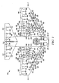
- FIG. 1 is a schematic diagram of a portion of an exemplary embodiment of an aircraft depicting an exemplary flight control surface actuation system according one embodiment of the present invention.
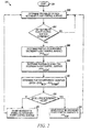
- FIG. 2 is a flowchart depicting an exemplary methodology implemented by the exemplary system of FIG. 1, according to an embodiment of the present invention.
- FIG. 1 a schematic diagram of a portion of an exemplary aircraft and a portion of an exemplary flight control surface actuation system is shown.
- the aircraft 100 includes first and second aircraft wings 101-1 and 101-2, respectively, a pair of elevators 102, a rudder 104, and a pair of ailerons 106, which are the primary flight control surfaces, and a plurality of flaps 108, slats 112, and spoilers 114, which are the secondary flight control surfaces.
- the primary flight control surfaces 102-106 control aircraft movements about the aircraft pitch, yaw, and roll axes.
- the elevators 102 are used to control aircraft movement about the pitch axis
- the rudder 104 is used to control aircraft movement about the yaw axis
- the ailerons 106 control aircraft movement about the roll axis. It is noted, however, that aircraft movement about the yaw axis can also be achieved either by varying the thrust levels from the engines on opposing sides of the aircraft 100. It will additionally be appreciated that the aircraft 100 could include horizontal stabilizers (not shown).
- the secondary control surfaces 108-114 which are all disposed on the first and second aircraft wings 101-1, 101-2, influence the lift and drag of the aircraft 100.
- the flaps 108 and slats 112 may be moved from retracted positions to extended positions. In the extended position, the flaps 108 increase both lift and drag, and enable the aircraft 100 to descend more steeply for a given airspeed, and also enable the aircraft 100 get airborne over a shorter distance.
- the slats 112, in the extended position increase lift, and are typically used in conjunction with the flaps 108.
- the spoilers 114 reduce lift and when moved from retracted positions to extended positions, which is typically done during aircraft landing operations, may be used as air brakes to assist in slowing the aircraft 100.
- the flight control surfaces 102-114 are moved to deployed positions via a flight control surface actuation system 120.
- the flight control surface actuation system 120 includes one or more actuator control units 121, a plurality of primary flight control surface actuators, which include elevator actuators 122, rudder actuators 124, and aileron actuators 126, and a plurality of secondary control surface actuators, which include flap actuators 128, slat actuators 132, and spoiler actuators 134. It will be appreciated that the number of actuator control units 121 may vary. However, in the depicted embodiment, the flight control surface actuation system 120 includes two multi-channel actuator control units 121 (121-1, 121-2).
- the flight control surface actuation system 120 may be implemented using various numbers and types of flight control surface actuators 122-134.
- the number and type of flight control surface actuators 122-134 per flight control surface 102-114 may be varied. In the depicted embodiment, however, the system 120 is implemented such that two primary flight control surface actuators 122-126 are coupled to each primary flight control surface 102-16, and two secondary control surface actuators 128-134 are coupled to each secondary control surface 108-114,
- each of the primary surface actuators 122-126, each of the flap actuators 128, and each of the spoiler actuators 134 are preferably a linear-type actuator, such as, for example, a ballscrew actuator, and each of the slat actuators 132 are preferably a rotary-type actuator. It will be appreciated that this number and type of flight control surface actuators 122-134 are merely exemplary of a particular embodiment, and that other numbers and types of actuators 122-134 could also be used.
- the flight control surface actuation system 120 additionally includes a plurality of control surface position sensors 125.
- the control surface position sensors 125 sense the positions of the flight control surfaces 102-114 and supply control surface position feedback signals representative thereof. It will be appreciated that the control surface position sensors 125 may be implemented using any one of numerous types of sensors including, for example, linear variable differential transformers (LVDTs), rotary variable differential transformers (RVDTs), Hall effect sensors, resolvers, or potentiometers, just to name a few. In the depicted embodiment, a pair of control surface position sensors 125 is coupled to each of the flight control surfaces 102-114.
- LVDTs linear variable differential transformers
- RVDTs rotary variable differential transformers
- Hall effect sensors resolvers
- potentiometers just to name a few.
- a pair of control surface position sensors 125 is coupled to each of the flight control surfaces 102-114.
- the flight control surface actuators 122-134 are each driven by one or more non-illustrated motors.
- the motors may be either electric, pneumatic, or hydraulic motors, in a particular preferred embodiment the motors are electric motors.
- various numbers of motors could be associated with each actuator, preferably two motors are associated with each flight control surface actuator 122-134 such that either, or both, actuator motors can drive the associated actuator 122-134.
- the actuator motors are selectively energized and, upon being energized, rotate in one direction or another, to thereby supply a drive force to the associated actuator 122-134.
- the actuators 122-134 are each coupled to receive the drive force supplied from its associated actuator motors and, depending on the direction in which the actuator motors rotate, move to commanded positions, to thereby move the primary and secondary flight control surfaces 102-114.
- the actuator motors may be implemented as any one of numerous types of AC or DC motors, but in a preferred embodiment the actuator motors are preferably implemented as DC motors, and most preferably brushless DC motors.
- the system 120 and actuator control units 121-1, 121-2 may be implemented according to any one of numerous operational configurations.
- the system 120 could be configured such that one of the control units 121-1 (121-2) is an active control unit, while the other control unit 121-2 (121-1) is in an inactive (or standby) mode.
- the system 120 could be configured such that both control units 121-1, 121-2 are active and controlling all, or selected ones, of the flight control surface actuator assemblies 122-134.
- each control unit 121-1, 121-2 when active, receives flight control surface position commands from one or more non-illustrated external systems, such as one or more flight control computers or pilot controls.
- the active control units 121-1, 121-2 energize the appropriate flight control surface actuator assemblies 122-134.
- the flight control surface actuator assemblies 122-134 in response to being energized, move the appropriate flight control surfaces 102-114 to the commanded flight control surface position.
- the control units 121-1, 121-2 may also be configured receive one or more monitor signals that are representative of secondary flight control surface actuator assembly 108-114 operability.
- the control units 121-1, 121-2 in response to these monitor signals, determine the operability of the secondary flight control surfaces 108-114. If one or both control units 121-1, 121-2 determines that a secondary flight control surface 108-114 is partially or fully inoperable, it automatically compensates the system 120 to prevent an asymmetric deploy configuration. It will be appreciated that a partially or fully inoperable secondary flight control surface may be caused by a jam or other fault associated with the flight control surface 108-114 itself, or by one or more partially or fully inoperable secondary flight control surface actuator assemblies 128.134. It will additionally be appreciated that the monitor signals that the control units 121-1, 121-2 receive may be supplied directly from the flight control surfaces actuator assemblies 108-114. In the depicted embodiment, however, the monitor signals are supplied from the secondary flight control surface position sensors 125.
- the control units 121 in response to the position signals supplied from the secondary flight control surface position sensors 125, determines the status and position of each secondary flight control surface 108-114. If one or both of the control units 121-1,121-2 determines that the system 120 is in, or would be in, an asymmetric deploy condition due to one or more of the secondary flight control surfaces 108-114 on one of the aircraft wings 101-1 (101-2) becoming inoperable, one or both control units 121-1, 121-1 either supplies actuator position commands to, or inhibits actuator position commands from being supplied to, the symmetric secondary flight control surface actuators 128-134 on the other aircraft wing 101-2 (101-1). Thus, the symmetric secondary flight control surface 108-114 is either moved to, or remains in, the same position as the inoperable secondary flight control surface 108-114.
- control units 121-1, 121-2 may implement the above-described functionality via hardware, firmware, software, or various combinations thereof. Preferably, however, the control units 121-1, 121-2 implement this functionality via software. It will additionally be appreciated that one or both of the actuator control units 121-1, 121-2 could be formed as an integral part of, and/or one or more of its above-described functions could be implemented as within, the one or more flight control computers. In any case, the process that is implemented by the control units 121-1,121-2 (either separately or as part of one or more flight control computers) is depicted in flowchart form in FIG. 2 and, for completeness of explanation, will now be described. In doing so, it should be understood that the parenthetical references in the following description correspond to the reference numerals used in the depicted flowchart.
- the operable control unit 121 determines the operability of each of the secondary flight control surfaces 108-114 (202, 204). As noted above, this can be accomplished using any one of numerous techniques, but is preferably accomplished via the position signals received from the secondary flight control surface position sensors 125. If a secondary flight control surface 108-114 is determined to be inoperable, the control unit 12] (or units) then determines the position of the inoperable secondary flight control surface 108-114 (206) and the position of the symmetric secondary flight control surface 108-114 on the opposite aircraft wing 101 (208).
- a magnitude difference between the two positions is determined (210), and compared to a predetermined value (212). If the magnitude difference equals or exceeds the predetermined value, then the symmetric secondary flight control surface 108-114 is moved to a position that is at least substantially equal to the position of the inoperable secondary flight control surface 108-114 (214). If, however, the magnitude difference is less than the predetermined value, then the symmetric secondary flight control surface 108-114 is already in a position that is at least substantially equal to the position of the inoperable flight control surface 108-114, and need not be moved.
Landscapes
- Engineering & Computer Science (AREA)
- Automation & Control Theory (AREA)
- Aviation & Aerospace Engineering (AREA)
- Control Of Position, Course, Altitude, Or Attitude Of Moving Bodies (AREA)
- Transmission Devices (AREA)
- Toys (AREA)
Applications Claiming Priority (2)
| Application Number | Priority Date | Filing Date | Title |
|---|---|---|---|
| US73682305P | 2005-11-14 | 2005-11-14 | |
| US11/387,583 US20070108342A1 (en) | 2005-11-14 | 2006-03-23 | Reconfigurable flight control surface actuation system and method |
Publications (2)
| Publication Number | Publication Date |
|---|---|
| EP1785347A2 true EP1785347A2 (fr) | 2007-05-16 |
| EP1785347A3 EP1785347A3 (fr) | 2008-03-12 |
Family
ID=37738287
Family Applications (1)
| Application Number | Title | Priority Date | Filing Date |
|---|---|---|---|
| EP06123905A Withdrawn EP1785347A3 (fr) | 2005-11-14 | 2006-11-13 | Système d'actionnement reconfigurable pour surfaces de commande de vol et procédé |
Country Status (2)
| Country | Link |
|---|---|
| US (1) | US20070108342A1 (fr) |
| EP (1) | EP1785347A3 (fr) |
Cited By (3)
| Publication number | Priority date | Publication date | Assignee | Title |
|---|---|---|---|---|
| EP1803644A3 (fr) * | 2005-12-27 | 2008-05-21 | Honeywell International Inc. | Système distribué d'actionnement d'une surface de commande de vol |
| EP3415417A1 (fr) * | 2017-06-15 | 2018-12-19 | The Boeing Company | Procédé et appareil pour un système de commande distribué d'aéronef |
| CN110901894A (zh) * | 2018-09-17 | 2020-03-24 | 空中客车营运有限公司 | 用于飞行器部件的致动器、机翼、飞行器及机翼设计方法 |
Families Citing this family (5)
| Publication number | Priority date | Publication date | Assignee | Title |
|---|---|---|---|---|
| CA2793443A1 (fr) * | 2010-03-18 | 2011-09-22 | Emc2 Holdings Llc | Systeme pour le diagnostic et le traitement de symptomes diabetiques |
| US10065728B2 (en) * | 2011-06-30 | 2018-09-04 | Parker-Hannifin Corporation | Horizontal stabilizer trim actuator failure detection system and method using position sensors |
| US10933978B2 (en) | 2017-01-10 | 2021-03-02 | Parker-Hannifin Corporation | Moving end electronic detection of secondary load path engagement of aircraft flight control actuator |
| KR102639235B1 (ko) * | 2021-12-28 | 2024-02-22 | 주식회사 제이앤에스 | 독립적이고 동시에 구동되는 좌우 쌍으로 이루어진 항공기 보조날개 제어의 고장시의 제어 방법 |
| US20240308648A1 (en) * | 2023-03-16 | 2024-09-19 | Honeywell International Inc. | Fly-by-wire flight control system with back-up control in an inceptor |
Citations (1)
| Publication number | Priority date | Publication date | Assignee | Title |
|---|---|---|---|---|
| WO2005047108A1 (fr) | 2003-11-12 | 2005-05-26 | Airbus Deutschland Gmbh | Procede pour limiter la charge dans un systeme d'entrainement pour systeme de portance elevee pour avion |
Family Cites Families (17)
| Publication number | Priority date | Publication date | Assignee | Title |
|---|---|---|---|---|
| US2834010A (en) * | 1955-07-22 | 1958-05-06 | Lundy Mfg Corp | Automatic power cut-off system for aircraft control surfaces |
| US3841589A (en) * | 1972-09-25 | 1974-10-15 | Lucas Aerospace Ltd | Actuating arrangements for aircraft control surfaces |
| GB1591799A (en) * | 1976-11-24 | 1981-06-24 | Lucas Industries Ltd | Drive arrangement forlift control surfaces on all aircraft wings |
| JPS5431200A (en) * | 1977-08-10 | 1979-03-07 | Fuji Heavy Ind Ltd | High-lift apparatus for aircraft |
| US4191347A (en) * | 1977-10-05 | 1980-03-04 | Calco Manufacturing Company | Flap control circuitry |
| US4725020A (en) * | 1980-12-09 | 1988-02-16 | The Boeing Company | Control system incorporating structural feedback |
| US4441675A (en) * | 1982-06-25 | 1984-04-10 | Mcdonnell Douglas Corporation | High lift surface actuation system |
| US4521060A (en) * | 1983-11-17 | 1985-06-04 | Sundstrand Corporation | Hydraulic asymmetry detector |
| FR2603866A1 (fr) * | 1986-09-12 | 1988-03-18 | Messerschmitt Boelkow Blohm | Systeme de commande de gouvernes de profondeur |
| FR2606363B1 (fr) * | 1986-11-07 | 1989-03-03 | Aerospatiale | Systeme pour la commande des volets hypersustentateurs d'un aeronef |
| US5214972A (en) * | 1992-04-30 | 1993-06-01 | Alliedsignal Aerospace | Fault-tolerant linear electromechanical actuator |
| US5743490A (en) * | 1996-02-16 | 1998-04-28 | Sundstrand Corporation | Flap/slat actuation system for an aircraft |
| US6299108B1 (en) * | 1997-12-12 | 2001-10-09 | Jeffrey V. Lindstrom | Method and apparatus for detecting skew and asymmetry of an airplane flap |
| US6382566B1 (en) * | 1998-12-29 | 2002-05-07 | The Boeing Company | Method and apparatus for detecting skew and asymmetry of an airplane flap |
| DE10313728B4 (de) * | 2003-03-27 | 2011-07-21 | Airbus Operations GmbH, 21129 | Klappensystem am Tragflügel eines Starrflügel-Flugzeuges |
| US20040200928A1 (en) * | 2003-04-14 | 2004-10-14 | Arthur Degenholtz | Actuator and flap arrangement with actuator interconnection |
| DE10326799B3 (de) * | 2003-06-13 | 2004-12-16 | Airbus Deutschland Gmbh | Vorrichtung zur Betätigung von Klappenelementen an den Tragflächen eines Flugzeuges |
-
2006
- 2006-03-23 US US11/387,583 patent/US20070108342A1/en not_active Abandoned
- 2006-11-13 EP EP06123905A patent/EP1785347A3/fr not_active Withdrawn
Patent Citations (1)
| Publication number | Priority date | Publication date | Assignee | Title |
|---|---|---|---|---|
| WO2005047108A1 (fr) | 2003-11-12 | 2005-05-26 | Airbus Deutschland Gmbh | Procede pour limiter la charge dans un systeme d'entrainement pour systeme de portance elevee pour avion |
Cited By (6)
| Publication number | Priority date | Publication date | Assignee | Title |
|---|---|---|---|---|
| EP1803644A3 (fr) * | 2005-12-27 | 2008-05-21 | Honeywell International Inc. | Système distribué d'actionnement d'une surface de commande de vol |
| US7556224B2 (en) | 2005-12-27 | 2009-07-07 | Honeywell International Inc. | Distributed flight control surface actuation system |
| EP3415417A1 (fr) * | 2017-06-15 | 2018-12-19 | The Boeing Company | Procédé et appareil pour un système de commande distribué d'aéronef |
| US10450055B2 (en) | 2017-06-15 | 2019-10-22 | The Boeing Company | Methods and apparatus for a distributed aircraft actuation system |
| US11591070B2 (en) | 2017-06-15 | 2023-02-28 | The Boeing Company | Methods and apparatus for a distributed aircraft actuation system |
| CN110901894A (zh) * | 2018-09-17 | 2020-03-24 | 空中客车营运有限公司 | 用于飞行器部件的致动器、机翼、飞行器及机翼设计方法 |
Also Published As
| Publication number | Publication date |
|---|---|
| US20070108342A1 (en) | 2007-05-17 |
| EP1785347A3 (fr) | 2008-03-12 |
Similar Documents
| Publication | Publication Date | Title |
|---|---|---|
| EP1721825B1 (fr) | Système d'actionnement d'une surface de commande de vol avec commandes de serrure configurés avec redondance | |
| US7549605B2 (en) | Electric flight control surface actuation system for aircraft flaps and slats | |
| US7556224B2 (en) | Distributed flight control surface actuation system | |
| US7770842B2 (en) | Aircraft flight control surface actuation system communication architecture | |
| US8033509B2 (en) | Load optimized redundant flight control surface actuation system and method | |
| US8172174B2 (en) | Hybrid electromechanical/hydromechanical actuator and actuation control system | |
| US7610828B2 (en) | Flight control surface actuator assembly including a free trial mechanism | |
| US10538310B2 (en) | Near synchronous distributed hydraulic motor driven actuation system | |
| EP1721826B1 (fr) | Système d'actionnement d'une surface de commande de vol avec commandes configurées avec redondance | |
| US8080966B2 (en) | Motor control architecture for simultaneously controlling multiple motors | |
| US8814085B2 (en) | Fault-tolerant actuating system for adjusting flaps of an aircraft, comprising adjustment kinematics with a fixed pivot, and a method for monitoring an actuating system | |
| EP1908685B1 (fr) | Ensemble d'interface utilisateur actif équilibré par moteur | |
| EP2058227B1 (fr) | Système de régulation pour interface actif avec rétroaction de toucher et interconnexion utilisant des données soit de force ou de position | |
| EP3208189B1 (fr) | Système de surveillance de mouvement de surface de commande aérodynamique | |
| EP1942388A1 (fr) | Système de manche de commande de pilotage actif avec réponse électromagnétique passive | |
| US20120018578A1 (en) | Near synchronous controlled induction motor drive actuation system | |
| US20070007385A1 (en) | Electric flight control surface actuation system electronic architecture | |
| US20070235594A1 (en) | Pilot flight control stick feedback system | |
| US20070108342A1 (en) | Reconfigurable flight control surface actuation system and method | |
| EP3517427A1 (fr) | Frein à commande proportionnelle | |
| EP1781538B1 (fr) | Architecture de communication du systeme d'actionnement de la gouverne d'un avion |
Legal Events
| Date | Code | Title | Description |
|---|---|---|---|
| PUAI | Public reference made under article 153(3) epc to a published international application that has entered the european phase |
Free format text: ORIGINAL CODE: 0009012 |
|
| AK | Designated contracting states |
Kind code of ref document: A2 Designated state(s): AT BE BG CH CY CZ DE DK EE ES FI FR GB GR HU IE IS IT LI LT LU LV MC NL PL PT RO SE SI SK TR |
|
| AX | Request for extension of the european patent |
Extension state: AL BA HR MK YU |
|
| PUAL | Search report despatched |
Free format text: ORIGINAL CODE: 0009013 |
|
| AK | Designated contracting states |
Kind code of ref document: A3 Designated state(s): AT BE BG CH CY CZ DE DK EE ES FI FR GB GR HU IE IS IT LI LT LU LV MC NL PL PT RO SE SI SK TR |
|
| AX | Request for extension of the european patent |
Extension state: AL BA HR MK YU |
|
| 17P | Request for examination filed |
Effective date: 20080829 |
|
| 17Q | First examination report despatched |
Effective date: 20081014 |
|
| AKX | Designation fees paid |
Designated state(s): DE FR GB |
|
| STAA | Information on the status of an ep patent application or granted ep patent |
Free format text: STATUS: THE APPLICATION IS DEEMED TO BE WITHDRAWN |
|
| 18D | Application deemed to be withdrawn |
Effective date: 20100601 |