EP1785348A2 - Treibstoffsystem - Google Patents
Treibstoffsystem Download PDFInfo
- Publication number
- EP1785348A2 EP1785348A2 EP06255472A EP06255472A EP1785348A2 EP 1785348 A2 EP1785348 A2 EP 1785348A2 EP 06255472 A EP06255472 A EP 06255472A EP 06255472 A EP06255472 A EP 06255472A EP 1785348 A2 EP1785348 A2 EP 1785348A2
- Authority
- EP
- European Patent Office
- Prior art keywords
- metering valve
- fuel
- valve member
- pump
- further movement
- Prior art date
- Legal status (The legal status is an assumption and is not a legal conclusion. Google has not performed a legal analysis and makes no representation as to the accuracy of the status listed.)
- Granted
Links
Images
Classifications
-
- F—MECHANICAL ENGINEERING; LIGHTING; HEATING; WEAPONS; BLASTING
- F02—COMBUSTION ENGINES; HOT-GAS OR COMBUSTION-PRODUCT ENGINE PLANTS
- F02M—SUPPLYING COMBUSTION ENGINES IN GENERAL WITH COMBUSTIBLE MIXTURES OR CONSTITUENTS THEREOF
- F02M37/00—Apparatus or systems for feeding liquid fuel from storage containers to carburettors or fuel-injection apparatus; Arrangements for purifying liquid fuel specially adapted for, or arranged on, internal-combustion engines
-
- F—MECHANICAL ENGINEERING; LIGHTING; HEATING; WEAPONS; BLASTING
- F02—COMBUSTION ENGINES; HOT-GAS OR COMBUSTION-PRODUCT ENGINE PLANTS
- F02C—GAS-TURBINE PLANTS; AIR INTAKES FOR JET-PROPULSION PLANTS; CONTROLLING FUEL SUPPLY IN AIR-BREATHING JET-PROPULSION PLANTS
- F02C7/00—Features, components parts, details or accessories, not provided for in, or of interest apart form groups F02C1/00 - F02C6/00; Air intakes for jet-propulsion plants
- F02C7/22—Fuel supply systems
- F02C7/236—Fuel delivery systems comprising two or more pumps
-
- F—MECHANICAL ENGINEERING; LIGHTING; HEATING; WEAPONS; BLASTING
- F02—COMBUSTION ENGINES; HOT-GAS OR COMBUSTION-PRODUCT ENGINE PLANTS
- F02C—GAS-TURBINE PLANTS; AIR INTAKES FOR JET-PROPULSION PLANTS; CONTROLLING FUEL SUPPLY IN AIR-BREATHING JET-PROPULSION PLANTS
- F02C9/00—Controlling gas-turbine plants; Controlling fuel supply in air- breathing jet-propulsion plants
- F02C9/26—Control of fuel supply
- F02C9/263—Control of fuel supply by means of fuel metering valves
-
- F—MECHANICAL ENGINEERING; LIGHTING; HEATING; WEAPONS; BLASTING
- F02—COMBUSTION ENGINES; HOT-GAS OR COMBUSTION-PRODUCT ENGINE PLANTS
- F02D—CONTROLLING COMBUSTION ENGINES
- F02D33/00—Controlling delivery of fuel or combustion-air, not otherwise provided for
- F02D33/003—Controlling the feeding of liquid fuel from storage containers to carburettors or fuel-injection apparatus ; Failure or leakage prevention; Diagnosis or detection of failure; Arrangement of sensors in the fuel system; Electric wiring; Electrostatic discharge
- F02D33/006—Controlling the feeding of liquid fuel from storage containers to carburettors or fuel-injection apparatus ; Failure or leakage prevention; Diagnosis or detection of failure; Arrangement of sensors in the fuel system; Electric wiring; Electrostatic discharge depending on engine operating conditions, e.g. start, stop or ambient conditions
-
- F—MECHANICAL ENGINEERING; LIGHTING; HEATING; WEAPONS; BLASTING
- F04—POSITIVE - DISPLACEMENT MACHINES FOR LIQUIDS; PUMPS FOR LIQUIDS OR ELASTIC FLUIDS
- F04C—ROTARY-PISTON, OR OSCILLATING-PISTON, POSITIVE-DISPLACEMENT MACHINES FOR LIQUIDS; ROTARY-PISTON, OR OSCILLATING-PISTON, POSITIVE-DISPLACEMENT PUMPS
- F04C14/00—Control of, monitoring of, or safety arrangements for, machines, pumps or pumping installations
- F04C14/28—Safety arrangements; Monitoring
-
- F—MECHANICAL ENGINEERING; LIGHTING; HEATING; WEAPONS; BLASTING
- F04—POSITIVE - DISPLACEMENT MACHINES FOR LIQUIDS; PUMPS FOR LIQUIDS OR ELASTIC FLUIDS
- F04C—ROTARY-PISTON, OR OSCILLATING-PISTON, POSITIVE-DISPLACEMENT MACHINES FOR LIQUIDS; ROTARY-PISTON, OR OSCILLATING-PISTON, POSITIVE-DISPLACEMENT PUMPS
- F04C2270/00—Control; Monitoring or safety arrangements
- F04C2270/86—Detection
-
- F—MECHANICAL ENGINEERING; LIGHTING; HEATING; WEAPONS; BLASTING
- F05—INDEXING SCHEMES RELATING TO ENGINES OR PUMPS IN VARIOUS SUBCLASSES OF CLASSES F01-F04
- F05D—INDEXING SCHEME FOR ASPECTS RELATING TO NON-POSITIVE-DISPLACEMENT MACHINES OR ENGINES, GAS-TURBINES OR JET-PROPULSION PLANTS
- F05D2260/00—Function
- F05D2260/80—Diagnostics
Definitions
- the invention relates to a fuel system and in particular to a fuel system for use in supplying fuel to an aircraft engine.
- the invention relates, in particular to a method and apparatus for determining the operating characteristics, and in particular the extent of internal wear, of a fuel pump forming part of such a fuel system.
- a fuel system for use in the delivery of fuel to an aircraft engine typically comprises a primary constant displacement fuel pump arranged to supply fuel through a metering valve and a pressure raising and shut-off valve to the burners of an engine.
- a spill valve is arranged to maintain a substantially constant pressure drop across the metering valve by spilling fuel back to the inlet of the fuel pump.
- a second pump is arranged to operate in parallel with the aforementioned primary pump to assist the primary pump during high demand phases of the engine operating cycle.
- a method of operating a fuel system to determine the extent of internal wear of a fuel pump thereof comprising driving the fuel pump, moving a metering valve member to a closed position in which it bears against a resilient stop, increasing the operating speed of the fuel pump to increase the pressure applied to the metering valve member urging it towards the resilient stop to a point beyond which further movement of the metering valve member occurs, sensing when the further movement of the metering valve member occurs, and sensing the operating speed of the pump at the time when said further movement occurs.
- the resilient stop is conveniently biassed by a spring, and preferably comprises a dump valve.
- the further movement of the metering valve member may be sensed by a position sensor used in normal control of the operation of the metering valve.
- the said further movement of the metering valve member occurs when the pressure applied thereto exceeds a substantially constant predetermined pressure.
- the sensed operating speed is stored to allow a wear profile of the pump to be built up over time.
- the stored data may be used to allow estimation of the remaining operating lifetime of the pump and scheduling of its replacement.
- the invention also relates to a fuel system comprising a fuel pump operable to supply fuel to a metering valve, the metering valve comprising a valve member movable under the influence of the fuel pressure applied thereto, a resilient stop limiting closing movement of the metering valve member when the pressure applied thereto is less than a predetermined level and allowing further movement of the metering valve member to occur when the applied pressure exceeds the predetermined level, sensor means for sensing said further movement of the metering valve member, and means operable to sense the operating speed of the fuel pump when said further movement of the metering valve member occurs.
- the movable stop conveniently comprises a dump valve.
- the method of the invention may be incorporated into the normal engine start procedure, and is suitable for retrofitting into existing systems.
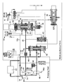
- Figure 1 is a diagram illustrating a fuel system in accordance with an embodiment of the invention.
- the fuel system illustrated diagrammatically in Figure 1 comprises a low pressure pump 10 arranged to supply fuel through a filter 12 to the inlet 14 of a primary gear pump 16.
- the pump 16 supplies fuel through a supply line 18 in which is located a flow washed filter 18 a to an inlet port 20 of a metering valve 22.
- the metering valve 22 is of substantially conventional form and comprises a valve member in the form of a spool 24 movable within a bore 26 under the influence of the fuel pressures within chambers 28, 30 formed at the ends of the spool 24.
- a servo valve arrangement 32 is used to control the relative pressures applied to the chambers 28, 30. For example, if it is desired to lift the spool 24, in the orientation illustrated, the chamber 30 is supplied with fuel at a higher pressure than that of chamber 28 by reducing the communication between the chamber 30 and the low pressure in line 32 a and increasing the communication between the chamber 28 and the low pressure in line 32 a .
- a position sensor 34 for example in the form of an LVDT is provided to monitor the position occupied by the spool 24, the output of the sensor 34 being used in the control of the operation of the servo valve 32 so as to allow the operation of the metering valve 22 to be controlled in a closed-loop fashion.
- the metering valve 22 includes an outlet port 36 connected through a pressure raising and shut-off valve 38 to the burners of an aircraft engine.
- the spool 24 partially obscures the outlet 36, and the rate at which fuel is able to flow through the metering valve 22 is dependent upon the position occupied by the spool 24. It will be appreciated that by lifting the spool 24, the fuel supply rate is increased, downward movement of the spool 24 reducing the fuel supply rate, the spool 24 being movable to a position in which the supply of fuel through the metering valve is terminated.
- a combining spill valve arrangement 40 is provided and is operable to maintain a substantially uniform pressure drop across the metering valve 22. In the event that the pressure drop across the metering valve 22 exceeds a predetermined level, a pressure drop control valve 42 causes the combining spill valve 40 to open thereby allowing fuel to escape along a return path 44 back to the inlet 14 of the fuel pump 16.
- the fuel system further comprises a second fuel pump 46 arranged to deliver fuel to the filter 18 and metering valve 22 through a non-return valve 48 under certain operating conditions of the engine.
- a second fuel pump 46 arranged to deliver fuel to the filter 18 and metering valve 22 through a non-return valve 48 under certain operating conditions of the engine.
- a pressure relief valve 52 is provided between the outlet of the pump 16 and the inlet 14 thereof, the pressure relief valve 52 opening in the event of excessive pressures occurring at the outlet of the pump 16 in order to reduce the risk of damage thereto.
- the fuel system illustrated in Figure 1 further comprises a dump valve 54 operable, on engine shut-down, to drain fuel from the burner manifold.
- the dump valve 54 comprises a valve member 56 movable by the spool 24 of the metering valve 22 when the spool 24 is moved to its fully closed position, such movement of the dump valve member 56 opening the dump valve to allow such escape of fuel.
- the dump valve member 56 is biassed by a spring 58 towards a closed position and so other than when forced to its open position by the spool 24, the dump valve 54 will remain closed.
- fuel is supplied by the pump 16 through the metering valve 22 and the pressure raising and shut-off valve 38 to the burners of the engine.
- the pump 16 is driven from an output shaft of the engine and rotates at a speed proportional to engine speed. It will be appreciated, therefore, that the rate of fuel supply by the pump 16 is governed by the speed of operation of the engine.
- the fuel supply to the engine is controlled by the metering valve 22 which, in turn, is controlled by the operation of the servo valve 32.
- the combining spill valve 40 together with the operation of the pressure drop control valve 42 maintains a substantially constant pressure drop across the metering valve 22 thus ensuring that the rate at which fuel is supplied by the metering valve 22 is governed by the axial position of the spool 24.
- the fuel system operates substantially conventionally and so further detail of its operation is not included herein.
- the pressure raising and shut-off valve 38 is closed by a shut-off servo valve 38 a to terminate fuel supply to the engine burners.
- the metering valve 22 is also closed by supplying the chamber 28 of the metering valve 22 with fuel under pressure, the chamber 30 being connected to low pressure by the servo valve 32. It will be appreciated that under these circumstances the spool 24 is forced downwardly in the orientation illustrated, thus closing the outlet 36. The operation of moving the spool 24 downwards brings the spool 24 into engagement with the dump valve member 56, forcing the dump valve member 56 away from its seating against the action of the spring 58 and opening the dump valve 54 thereby allowing fuel to escape from the burner manifold. Engine shut down in this manner is, again, substantially conventional and will not be described in further detail.
- the engine is turned by an external drive, resulting in the fuel pumps 16, 46 being driven.
- the fuel pressure to which the combining spill valve 40 is exposed is relatively low so the spill valve 40 occupies a closed position in which the second pump 46 is unloaded and in which none of the fuel supplied by the primary pump 16 and the secondary pump 46 is returned through the lines 44 and 50.
- the servo valve 32 is held in a position in which the chamber 30 is held at a lower pressure than chamber 28.
- the chamber 28 is exposed to a pressure related to the pressure of the fuel supplied by the pump 16 to the line 18. It will be appreciated, therefore, that the spool 24 is urged downwardly towards its closed position by the pressure differential. Initially, the difference in pressure is relatively small and so the spool 24, although urged into engagement with the dump valve member 56, is unable to move the dump valve member 56 against the action of the spring 58.
- the further movement of the spool 24 is sensed by the sensor 34, and the engine/pump operating speed at the time of the further movement being sensed is measured, for example by sensing the operating speed of the engine or the external drive used to rotate the engine at this time, or using sensors 16 a , 46 a associated with the pumps.
- the measured speed may be used directly to provide an indication of the wear status of the pump, it is envisaged to store the measured speed data over time to allow a wear profile to be built up which can be used to monitor pump wear and to allow scheduling of pump replacement at the optimum time.
- the speed data may be stored with other data which could impact upon the pump operating speed required to develop the required pressure, for example altitude and fuel temperature.
- the metering valve 22 can be opened to commence fuel supply to the pressure raising and shut-off valve 38 to allow engine start-up to continue in the usual manner.
- the method could form part of a separate pump test procedure if desired.
- the invention may be retrofitted or implemented in existing fuel systems without requiring the replacement or modification of significant components thereof. It therefore is of wide ranging application.
Landscapes
- Engineering & Computer Science (AREA)
- Chemical & Material Sciences (AREA)
- Combustion & Propulsion (AREA)
- Mechanical Engineering (AREA)
- General Engineering & Computer Science (AREA)
- Fuel-Injection Apparatus (AREA)
Applications Claiming Priority (1)
| Application Number | Priority Date | Filing Date | Title |
|---|---|---|---|
| GBGB0522991.9A GB0522991D0 (en) | 2005-11-11 | 2005-11-11 | Fuel system |
Publications (3)
| Publication Number | Publication Date |
|---|---|
| EP1785348A2 true EP1785348A2 (de) | 2007-05-16 |
| EP1785348A3 EP1785348A3 (de) | 2009-04-22 |
| EP1785348B1 EP1785348B1 (de) | 2011-06-22 |
Family
ID=35516740
Family Applications (1)
| Application Number | Title | Priority Date | Filing Date |
|---|---|---|---|
| EP06255472A Not-in-force EP1785348B1 (de) | 2005-11-11 | 2006-10-24 | Kraftstoffsystem und Verfahren zur Bestimmung des Grades der internen Abnutzung einer Kraftstoffpumpe |
Country Status (3)
| Country | Link |
|---|---|
| US (1) | US7481102B2 (de) |
| EP (1) | EP1785348B1 (de) |
| GB (1) | GB0522991D0 (de) |
Cited By (8)
| Publication number | Priority date | Publication date | Assignee | Title |
|---|---|---|---|---|
| FR2923871A1 (fr) * | 2007-11-19 | 2009-05-22 | Hispano Suiza Sa | Surveillance d'une pompe haute-pression dans un circuit d'alimentation en carburant d'une turbomachine. |
| EP2339147A3 (de) * | 2009-12-22 | 2012-07-11 | Rolls-Royce Goodrich Engine Control Systems Ltd. | Regelungssystem für die Kraftstoffzufuhr eines Flugtriebwerks |
| FR2971563A1 (fr) * | 2011-02-15 | 2012-08-17 | Snecma | Procede et dispositif pour determiner si l'une ou l'autre de deux pompes en serie est hors service ou non |
| GB2492230A (en) * | 2011-06-22 | 2012-12-26 | Hamilton Sundstrand Corp | Fuel system health monitoring |
| FR2979957A1 (fr) * | 2011-09-13 | 2013-03-15 | Snecma | Procede de suivi du rendement volumetrique d'une pompe hp d'un systeme de regulation hydraulique de turbomachine |
| EP2891768A1 (de) * | 2014-01-06 | 2015-07-08 | Rolls-Royce Controls and Data Services Limited | Motorkraftstoffsteuerungssystem |
| WO2016048787A1 (en) * | 2014-09-23 | 2016-03-31 | Woodward, Inc. | Pump authority switching apparatus for a fluid distribution system |
| CN107740763A (zh) * | 2017-09-11 | 2018-02-27 | 郑州斯倍思机电有限公司 | 一种机油泵出厂性能试验台及其操作方法 |
Families Citing this family (13)
| Publication number | Priority date | Publication date | Assignee | Title |
|---|---|---|---|---|
| FR3013837B1 (fr) * | 2013-11-25 | 2015-12-18 | Snecma | Procede de test d'equipements a geometries variables d'un moteur d'aeronef, notamment de turbomachine |
| FR3028245B1 (fr) * | 2014-11-06 | 2019-05-24 | Airbus Operations | Circuit d'alimentation en carburant d'un aeronef |
| WO2019172372A1 (ja) | 2018-03-08 | 2019-09-12 | 株式会社Ihi | 燃料供給制御装置 |
| CN110318886A (zh) * | 2019-07-16 | 2019-10-11 | 中国航发沈阳发动机研究所 | 一种基于双联齿轮泵的燃油计量系统及其匹配方法 |
| CN110735723B (zh) * | 2019-10-22 | 2022-03-08 | 北京动力机械研究所 | 发动机控制器异常断电后流量调节活门位置保持系统 |
| CN111022689B (zh) * | 2019-11-21 | 2022-05-17 | 中国航发西安动力控制科技有限公司 | 一种可实现精确控制的燃油计量机构 |
| US11598302B2 (en) * | 2020-11-24 | 2023-03-07 | Caterpillar Inc. | Fuel pump health assessment system |
| CN113960949A (zh) * | 2021-11-25 | 2022-01-21 | 沈阳多元机电设备有限公司 | 燃油热沉试验控制电路 |
| WO2024023881A1 (ja) | 2022-07-25 | 2024-02-01 | 株式会社Ihi | 航空機用ガスタービンエンジンの燃料供給システム及び燃料供給方法 |
| US20240263589A1 (en) * | 2023-02-03 | 2024-08-08 | Woodward, Inc. | Systems and methods for dual, motor-driven pumping and direct metering |
| CN116025471B (zh) * | 2023-02-07 | 2025-09-26 | 中国航发四川燃气涡轮研究院 | 一种双联齿轮泵供油系统架构及双模转换方法 |
| US12258911B2 (en) * | 2023-08-21 | 2025-03-25 | Rolls-Royce Corporation | Fuel unit health monitoring system |
| US12345211B2 (en) | 2023-08-21 | 2025-07-01 | Rolls-Royce North American Technologies, Inc. | Uncommanded or uncontrollable high thrust detection and mitigation |
Family Cites Families (7)
| Publication number | Priority date | Publication date | Assignee | Title |
|---|---|---|---|---|
| GB2061401B (en) * | 1979-09-15 | 1983-09-01 | Lucas Industries Ltd | Test equipment |
| GB9723466D0 (en) * | 1997-11-07 | 1998-01-07 | Lucas Ind Plc | Fluid flow valve and fluid flow system |
| US6882924B2 (en) * | 2003-05-05 | 2005-04-19 | Precision Engine Controls Corp. | Valve flow control system and method |
| GB0317394D0 (en) * | 2003-07-25 | 2003-08-27 | Goodrich Control Sys Ltd | Engine fuel control |
| GB0323887D0 (en) * | 2003-10-11 | 2003-11-12 | Goodrich Control Sys Ltd | Pump health monitoring |
| GB0417034D0 (en) * | 2004-07-30 | 2004-09-01 | Goodrich Control Sys Ltd | Pressure regulator |
| GB0508126D0 (en) * | 2005-04-22 | 2005-06-01 | Goodrich Control Sys Ltd | Fuel system |
-
2005
- 2005-11-11 GB GBGB0522991.9A patent/GB0522991D0/en not_active Ceased
-
2006
- 2006-10-24 EP EP06255472A patent/EP1785348B1/de not_active Not-in-force
- 2006-11-01 US US11/555,335 patent/US7481102B2/en not_active Expired - Fee Related
Cited By (23)
| Publication number | Priority date | Publication date | Assignee | Title |
|---|---|---|---|---|
| RU2495265C2 (ru) * | 2007-11-19 | 2013-10-10 | Снекма | Устройство контроля насоса высокого давления в контуре питания топливом газотурбинного двигателя |
| WO2009101267A2 (fr) | 2007-11-19 | 2009-08-20 | Snecma | Surveillance d'une pompe haute-pression dans un circuit d'alimentation en carburant d'une turbomachine |
| WO2009101267A3 (fr) * | 2007-11-19 | 2009-10-22 | Snecma | Dispositif de surveillance d'une pompe haute-pression dans un circuit d'alimentation en carburant d'une turbomachine |
| CN101861451A (zh) * | 2007-11-19 | 2010-10-13 | 斯奈克玛 | 在涡轮发动机燃料供给回路中监测高压泵的方法和设备 |
| FR2923871A1 (fr) * | 2007-11-19 | 2009-05-22 | Hispano Suiza Sa | Surveillance d'une pompe haute-pression dans un circuit d'alimentation en carburant d'une turbomachine. |
| CN101861451B (zh) * | 2007-11-19 | 2015-01-28 | 斯奈克玛 | 在涡轮发动机燃料供给回路中监测高压泵的方法和设备 |
| US8857150B2 (en) | 2007-11-19 | 2014-10-14 | Snecma | Monitoring of a high-pressure pump in a turbine engine fuel supply circuit |
| EP2339147A3 (de) * | 2009-12-22 | 2012-07-11 | Rolls-Royce Goodrich Engine Control Systems Ltd. | Regelungssystem für die Kraftstoffzufuhr eines Flugtriebwerks |
| US8991186B2 (en) | 2009-12-22 | 2015-03-31 | Rolls-Royce Engine Control Systems Limited | Fuel control system with servo valve controlled windmill relight mode |
| FR2971563A1 (fr) * | 2011-02-15 | 2012-08-17 | Snecma | Procede et dispositif pour determiner si l'une ou l'autre de deux pompes en serie est hors service ou non |
| GB2492230B (en) * | 2011-06-22 | 2013-10-09 | Hamilton Sundstrand Corp | System and method for fuel system health monitoring |
| US8578763B2 (en) | 2011-06-22 | 2013-11-12 | Hamilton Sundstrand Corporation | System and method for fuel system health monitoring |
| GB2492230A (en) * | 2011-06-22 | 2012-12-26 | Hamilton Sundstrand Corp | Fuel system health monitoring |
| RU2606465C2 (ru) * | 2011-09-13 | 2017-01-10 | Снекма | Способ отслеживания кпд прямого вытеснения высоконапорного (вн) насоса в гидравлической системе регулирования турбомашины |
| FR2979957A1 (fr) * | 2011-09-13 | 2013-03-15 | Snecma | Procede de suivi du rendement volumetrique d'une pompe hp d'un systeme de regulation hydraulique de turbomachine |
| CN103917783A (zh) * | 2011-09-13 | 2014-07-09 | 斯奈克玛 | 监测涡轮机的液压控制系统中的高压泵的容积效率的方法 |
| US9309882B2 (en) | 2011-09-13 | 2016-04-12 | Snecma | Method of determining whether to replace a high pressure pump in a hydraulic regulation system of a turbomachine |
| WO2013038085A3 (fr) * | 2011-09-13 | 2014-03-20 | Snecma | Procede de suivi du rendement volumetrique d'une pompe hp d'un systeme de regulation hydraulique de turbomachine |
| EP2891768A1 (de) * | 2014-01-06 | 2015-07-08 | Rolls-Royce Controls and Data Services Limited | Motorkraftstoffsteuerungssystem |
| US9739208B2 (en) | 2014-01-06 | 2017-08-22 | Rolls-Royce Plc | Engine fuel control system |
| WO2016048787A1 (en) * | 2014-09-23 | 2016-03-31 | Woodward, Inc. | Pump authority switching apparatus for a fluid distribution system |
| US9850917B2 (en) | 2014-09-23 | 2017-12-26 | Woodward, Inc. | Pump authority switching apparatus for a fluid distribution system |
| CN107740763A (zh) * | 2017-09-11 | 2018-02-27 | 郑州斯倍思机电有限公司 | 一种机油泵出厂性能试验台及其操作方法 |
Also Published As
| Publication number | Publication date |
|---|---|
| US20070107435A1 (en) | 2007-05-17 |
| GB0522991D0 (en) | 2005-12-21 |
| US7481102B2 (en) | 2009-01-27 |
| EP1785348B1 (de) | 2011-06-22 |
| EP1785348A3 (de) | 2009-04-22 |
Similar Documents
| Publication | Publication Date | Title |
|---|---|---|
| EP1785348B1 (de) | Kraftstoffsystem und Verfahren zur Bestimmung des Grades der internen Abnutzung einer Kraftstoffpumpe | |
| US8720482B2 (en) | Fuel system | |
| US8857150B2 (en) | Monitoring of a high-pressure pump in a turbine engine fuel supply circuit | |
| RU2398124C2 (ru) | Устройство питания топливом газотурбинного двигателя с регулируемым расходом топлива | |
| US9771906B2 (en) | Engine fuel control system | |
| RU2399778C2 (ru) | Питание топливом двигателя летательного аппарата | |
| EP1522731B1 (de) | Pumpenzustandsüberwachung | |
| EP2417383B1 (de) | Sperrventil zur flusserfassung | |
| JP4321342B2 (ja) | コモンレール式燃料噴射装置 | |
| US8991186B2 (en) | Fuel control system with servo valve controlled windmill relight mode | |
| EP2762711B1 (de) | Motorkraftstoffsteuerungssystem | |
| EP2441946B1 (de) | Verbessertes System zur Kraftstoffdruckregulierung und verbesserter Kraftstoffdruckregler dafür | |
| EP1923544B1 (de) | Brennstoffsystem und Ökoventil zur Verwendung dabei | |
| EP1712775A1 (de) | Krafstoffzufuhrvorrichtung | |
| EP1198664B1 (de) | Entleervorrichtung für das kraftstoffzufuhrsystem eines gasturbinentriebwerks | |
| JP2005061399A (ja) | 潤滑装置および潤滑方法 | |
| JP2001527181A (ja) | 始動・遮断・超過速度システム | |
| US5086617A (en) | Gas turbine engine fuel control system, and metering valve | |
| CN103261644A (zh) | 内燃机的燃油喷射系统以及相关的压力调节方法 | |
| JP2008175208A (ja) | ターボ機械における燃料噴射装置 | |
| EP2479408A2 (de) | Kraftstoffsystem für Flugzeugtriebwerke | |
| US20100121553A1 (en) | Engine Relight Method | |
| JP2008138566A (ja) | エンジンの燃料噴射装置及び運転方法 | |
| EP1944486B1 (de) | Brennstoffsystem für ein Flugtriebwerk | |
| RU43595U1 (ru) | Система подачи топлива в газотурбинный двигатель |
Legal Events
| Date | Code | Title | Description |
|---|---|---|---|
| PUAI | Public reference made under article 153(3) epc to a published international application that has entered the european phase |
Free format text: ORIGINAL CODE: 0009012 |
|
| AK | Designated contracting states |
Kind code of ref document: A2 Designated state(s): AT BE BG CH CY CZ DE DK EE ES FI FR GB GR HU IE IS IT LI LT LU LV MC NL PL PT RO SE SI SK TR |
|
| AX | Request for extension of the european patent |
Extension state: AL BA HR MK YU |
|
| PUAL | Search report despatched |
Free format text: ORIGINAL CODE: 0009013 |
|
| AK | Designated contracting states |
Kind code of ref document: A3 Designated state(s): AT BE BG CH CY CZ DE DK EE ES FI FR GB GR HU IE IS IT LI LT LU LV MC NL PL PT RO SE SI SK TR |
|
| AX | Request for extension of the european patent |
Extension state: AL BA HR MK RS |
|
| RIC1 | Information provided on ipc code assigned before grant |
Ipc: B64D 37/00 20060101AFI20070214BHEP Ipc: F04C 14/00 20060101ALI20090319BHEP Ipc: F02C 9/26 20060101ALI20090319BHEP Ipc: F02M 37/00 20060101ALI20090319BHEP |
|
| 17P | Request for examination filed |
Effective date: 20091008 |
|
| AKX | Designation fees paid |
Designated state(s): DE ES FR GB IT |
|
| GRAP | Despatch of communication of intention to grant a patent |
Free format text: ORIGINAL CODE: EPIDOSNIGR1 |
|
| RTI1 | Title (correction) |
Free format text: FUEL SYSTEM AND METHOD FOR DETERMINING THE EXTENT OF INTERNAL WEAR OF A FUEL PUMP |
|
| GRAS | Grant fee paid |
Free format text: ORIGINAL CODE: EPIDOSNIGR3 |
|
| GRAA | (expected) grant |
Free format text: ORIGINAL CODE: 0009210 |
|
| AK | Designated contracting states |
Kind code of ref document: B1 Designated state(s): DE ES FR GB IT |
|
| REG | Reference to a national code |
Ref country code: GB Ref legal event code: FG4D |
|
| REG | Reference to a national code |
Ref country code: DE Ref legal event code: R096 Ref document number: 602006022636 Country of ref document: DE Effective date: 20110811 |
|
| PLBE | No opposition filed within time limit |
Free format text: ORIGINAL CODE: 0009261 |
|
| STAA | Information on the status of an ep patent application or granted ep patent |
Free format text: STATUS: NO OPPOSITION FILED WITHIN TIME LIMIT |
|
| 26N | No opposition filed |
Effective date: 20120323 |
|
| PG25 | Lapsed in a contracting state [announced via postgrant information from national office to epo] |
Ref country code: IT Free format text: LAPSE BECAUSE OF FAILURE TO SUBMIT A TRANSLATION OF THE DESCRIPTION OR TO PAY THE FEE WITHIN THE PRESCRIBED TIME-LIMIT Effective date: 20110622 |
|
| REG | Reference to a national code |
Ref country code: DE Ref legal event code: R097 Ref document number: 602006022636 Country of ref document: DE Effective date: 20120323 |
|
| PGFP | Annual fee paid to national office [announced via postgrant information from national office to epo] |
Ref country code: FR Payment date: 20121018 Year of fee payment: 7 Ref country code: DE Payment date: 20121017 Year of fee payment: 7 |
|
| PGFP | Annual fee paid to national office [announced via postgrant information from national office to epo] |
Ref country code: GB Payment date: 20121024 Year of fee payment: 7 |
|
| PG25 | Lapsed in a contracting state [announced via postgrant information from national office to epo] |
Ref country code: ES Free format text: LAPSE BECAUSE OF FAILURE TO SUBMIT A TRANSLATION OF THE DESCRIPTION OR TO PAY THE FEE WITHIN THE PRESCRIBED TIME-LIMIT Effective date: 20111003 |
|
| REG | Reference to a national code |
Ref country code: DE Ref legal event code: R081 Ref document number: 602006022636 Country of ref document: DE Owner name: GOODRICH CONTROL SYSTEMS, GB Free format text: FORMER OWNER: GOODRICH CONTROL SYSTEMS LTD., SOLIHULL, GB Effective date: 20140220 Ref country code: DE Ref legal event code: R082 Ref document number: 602006022636 Country of ref document: DE Representative=s name: MARKS & CLERK (LUXEMBOURG) LLP, LU Effective date: 20140220 Ref country code: DE Ref legal event code: R081 Ref document number: 602006022636 Country of ref document: DE Owner name: GOODRICH CONTROL SYSTEMS, GB Free format text: FORMER OWNER: GOODRICH CONTROL SYSTEMS LTD., SOLIHULL, GB Effective date: 20110620 Ref country code: DE Ref legal event code: R081 Ref document number: 602006022636 Country of ref document: DE Owner name: GOODRICH CONTROL SYSTEMS, SOLIHULL, GB Free format text: FORMER OWNER: GOODRICH CONTROL SYSTEMS LTD., SOLIHULL, WEST MIDLANDS, GB Effective date: 20140220 Ref country code: DE Ref legal event code: R081 Ref document number: 602006022636 Country of ref document: DE Owner name: GOODRICH CONTROL SYSTEMS, SOLIHULL, GB Free format text: FORMER OWNER: GOODRICH CONTROL SYSTEMS LTD., SOLIHULL, WEST MIDLANDS, GB Effective date: 20110620 |
|
| GBPC | Gb: european patent ceased through non-payment of renewal fee |
Effective date: 20131024 |
|
| PG25 | Lapsed in a contracting state [announced via postgrant information from national office to epo] |
Ref country code: GB Free format text: LAPSE BECAUSE OF NON-PAYMENT OF DUE FEES Effective date: 20131024 |
|
| REG | Reference to a national code |
Ref country code: FR Ref legal event code: ST Effective date: 20140630 |
|
| REG | Reference to a national code |
Ref country code: DE Ref legal event code: R119 Ref document number: 602006022636 Country of ref document: DE Effective date: 20140501 |
|
| PG25 | Lapsed in a contracting state [announced via postgrant information from national office to epo] |
Ref country code: FR Free format text: LAPSE BECAUSE OF NON-PAYMENT OF DUE FEES Effective date: 20131031 Ref country code: DE Free format text: LAPSE BECAUSE OF NON-PAYMENT OF DUE FEES Effective date: 20140501 |