EP1785534B1 - Bouche d'égout - Google Patents
Bouche d'égout Download PDFInfo
- Publication number
- EP1785534B1 EP1785534B1 EP06123934A EP06123934A EP1785534B1 EP 1785534 B1 EP1785534 B1 EP 1785534B1 EP 06123934 A EP06123934 A EP 06123934A EP 06123934 A EP06123934 A EP 06123934A EP 1785534 B1 EP1785534 B1 EP 1785534B1
- Authority
- EP
- European Patent Office
- Prior art keywords
- housing part
- drainage device
- drainage
- shaped
- grate
- Prior art date
- Legal status (The legal status is an assumption and is not a legal conclusion. Google has not performed a legal analysis and makes no representation as to the accuracy of the status listed.)
- Active
Links
Images


Classifications
-
- E—FIXED CONSTRUCTIONS
- E03—WATER SUPPLY; SEWERAGE
- E03C—DOMESTIC PLUMBING INSTALLATIONS FOR FRESH WATER OR WASTE WATER; SINKS
- E03C1/00—Domestic plumbing installations for fresh water or waste water; Sinks
- E03C1/12—Plumbing installations for waste water; Basins or fountains connected thereto; Sinks
- E03C1/22—Outlet devices mounted in basins, baths, or sinks
-
- E—FIXED CONSTRUCTIONS
- E03—WATER SUPPLY; SEWERAGE
- E03F—SEWERS; CESSPOOLS
- E03F5/00—Sewerage structures
- E03F5/04—Gullies inlets, road sinks, floor drains with or without odour seals or sediment traps
- E03F5/0407—Floor drains for indoor use
- E03F5/0408—Floor drains for indoor use specially adapted for showers
-
- E—FIXED CONSTRUCTIONS
- E03—WATER SUPPLY; SEWERAGE
- E03F—SEWERS; CESSPOOLS
- E03F5/00—Sewerage structures
- E03F5/04—Gullies inlets, road sinks, floor drains with or without odour seals or sediment traps
- E03F2005/0412—Gullies inlets, road sinks, floor drains with or without odour seals or sediment traps with means for adjusting their position with respect to the surrounding surface
- E03F2005/0413—Gullies inlets, road sinks, floor drains with or without odour seals or sediment traps with means for adjusting their position with respect to the surrounding surface for height adjustment
-
- E—FIXED CONSTRUCTIONS
- E03—WATER SUPPLY; SEWERAGE
- E03F—SEWERS; CESSPOOLS
- E03F5/00—Sewerage structures
- E03F5/04—Gullies inlets, road sinks, floor drains with or without odour seals or sediment traps
- E03F2005/0416—Gullies inlets, road sinks, floor drains with or without odour seals or sediment traps with an odour seal
- E03F2005/0418—Gullies inlets, road sinks, floor drains with or without odour seals or sediment traps with an odour seal in the form of a bell siphon
Definitions
- the invention relates to a sanitary drainage device for producing a water drain embedded in a bottom, with a grate, a box-shaped housing having a drain opening and carrying the grate, an odor trap and a drain pipe releasably connectable with a drainage line, wherein the housing consists of a cup-shaped housing lower part and a lid-like upper housing part is constructed, and wherein the upper housing part height adjustable relative to the lower housing part connected to the same and having anchoring means which serve to anchor the upper housing part in a screed.
- Such a drain device is from the CH 682827 A5 known.
- the known drainage device serves as a floor drain. It comprises a housing with an overhead inlet opening into which an inlet pipe having top part is height adjustable inserted, wherein the inlet pipe by means of a clamping ring on the housing can be locked.
- the upper part also has a frame for receiving a drain grate which rests on a shoulder attached to the frame.
- the housing consists of two U-shaped bent sheets. The inner of these two sheets is V-shaped in the lowermost region, forms a siphon together with a separating plate and is spaced from the bottom surface of the outer sheet.
- the bottom part of the outer sheet is provided with a bore into which a nail or a screw for fixing the housing can be inserted.
- the U-shaped curved inner plate of the housing is also provided with a lateral, slightly inclined down drain pipe.
- the functionally reliable embedding of the drain in the screed is not always easy. Occasionally, during or after the screed is laid, it is found that the drain has been positioned too high or too low relative to the top of the screed. Leveling is then often difficult and can lead to sealing defects as well as slope failure and resulting water drainage problems.
- the present invention is therefore an object of the invention to provide a drain device of the type mentioned, which overcomes the above problems.
- the drainage device comprises a grate, a housing having a drain opening and carrying the grate, an odor trap and a drain neck detachably connectable to a drainage line.
- the housing is constructed in the form of a box-shaped housing from a cup-shaped housing lower part and a lid-like housing upper part, wherein the odor trap is arranged in its position relative to the housing upper part and / or the lower housing part adjustable in the housing.
- the upper housing part is height adjustable relative to the lower housing part connected to the same and provided with anchoring means which serve to anchor the upper housing part in a screed.
- the housing of the drainage device according to the invention thus advantageously allows a height adjustment of the sealing level of the process until immediately before the screed laying.
- the process in particular its odor trap, is protected by the housing against damage before or during screed laying.
- the anchoring means of the housing upper part cause a stable and reliable connection of the housing to the screed.
- a structure-borne noise decoupling of the housing to the subfloor (concrete floor) achieved or enabled.
- a damping layer for example a foam film or the like, can be arranged in advance underneath the housing, ie below the housing lower part.
- the upper housing part of the drain device according to the invention on the upper side an annular, the drain opening surrounding recess in which an annular disc-shaped element having an eccentrically arranged aperture, is rotatably received, wherein the annular disk-shaped element has a recess on top, in which the grate substantially is arranged horizontally displaceable.
- the height adjustability of the housing and its protective function can be structurally relatively easily realized by the upper housing part is designed such that it surrounds the lower edge of the housing at the edge.
- the height of the upper housing part relative to the lower housing part can preferably be adjusted and / or determined by means of screws fastened to the upper housing part and / or to the lower housing part.
- the lower housing part is provided with fastening straps.
- the lower part of the housing can thus be fixed with screws to the subfloor.
- a piece of pipe is arranged between the odor trap and the outlet nozzle, which is connected to both the odor trap and the drainage spigot and liquid-tight. If it should turn out during the subsequent screed laying that the box-shaped housing is positioned at the wrong height, the housing can also be subsequently corrected in the height in both directions by the double joint at the outlet connection.
- the annular disk-shaped element is provided on the upper side with a plurality of grooves which open at the opening.
- the grooves extend from the opening in the radial direction and each have a groove bottom inclined in the direction of the opening.
- a further preferred embodiment of the drainage device according to the invention consists in that one or more frame-shaped washers are assigned to the grate or to a grate-receiving frame. By means of one or more of these washers, the height of the upper edge of the grate can be adapted to different tile or natural stone slab thicknesses.
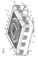
- the drain device 1 shown in the drawing is in particular for producing a floor-level shower certainly.
- the drain 3 provided with an odor trap 2 is arranged in a two-part, box-shaped housing 4.
- the housing 4 of the drainage device 1 is constructed from a lower housing part 4.1 and a housing upper part 4.2 having a drain opening 5 and thus enables height adjustment for adaptation to the floor construction.
- the lower housing part 4.1 is formed shell-shaped and has a bottom 6 and four walls oriented substantially at right angles to each other, wherein the cover-like, also shell-shaped upper housing part 4.2 surrounds the lower housing part 4.1 edge side.
- the designated 7 wall of the housing base 4.1 has a recess 8 for the passage of a drain nozzle 9.
- a recess 10 is provided in the housing lower part 4.1 enclosing wall of the housing upper part 4.2 . Both recesses 8 and 10 are substantially U-shaped and extend to the upper edge of the housing base 4.1 or to the lower edge of the upper housing part 4.2.
- the opposite walls 7 and 11 of the lower housing part 4.1 are provided with threaded holes, are screwed into the locking screws 12, which pass through vertically extending slots 13 in the opposite walls of the upper housing part 4.2.
- Structure-borne sound damping means 14 are arranged between the mutually facing walls of the two housing parts 4.1 and 4.2.
- the structure-borne noise damping means 14 may consist, for example, of foam strips glued to the inside of the walls of the housing upper part, in particular of foam rubber strips.
- the lower housing part 4.1 and the upper housing part 4.2 are preferably made of plastic, for example made of fiber-reinforced polypropylene, acrylonitrile-butadiene-styrene (ABS) or other materials.
- plastic for example made of fiber-reinforced polypropylene, acrylonitrile-butadiene-styrene (ABS) or other materials.
- anchoring means 16 serve to establish a stable connection of the housing to the surrounding screed.
- the anchoring means 16 also reinforce the upper housing part 4.2 and are formed in this embodiment in the form of corrugated ribs.
- the upper side of the upper housing part 4.2 has a grid-shaped structure 17, which consists of lattice-like grooves 18 and flat, rectangular elevations 19. Reinforcing webs 20 are integrally formed on the underside of the cover-like housing upper part 4.2.
- the drain 3 located in the box-shaped housing 4 has an odor trap 2, which is formed from a cup-shaped plastic part 2.1 into which a nozzle-shaped separating channel protrudes 2.2 whose lower edge defines a deflection and the bottom of the cup-shaped plastic part 2.1 is spaced.
- a bell-shaped elevation 2.3 is formed, which projects into the separation channel 2.2.
- the pot-shaped plastic part 2.1 has a circumferential overflow edge 2.4, which, viewed from the outside, merges into an annular overflow channel 2.5, which in turn is inserted into a nozzle-shaped section 2.6 passes.
- the annular overflow channel 2.5 is formed in the direction of the nozzle-shaped portion 2.6 with a slope.
- the odor trap 2 also has an annular cover part 2.7, which covers the annular overflow channel 2.5 liquid-tight and at its opening 2.8 liquid-tight with the protruding into the cup-shaped plastic part 2.1 separation channel 2.2 is connected.
- the nozzle-shaped portion 2.6 of the drain or odor trap has a spherical thickening, which forms a ball joint together with a pipe section 21.
- the pipe section 21 also has a spherical thickening, which forms a ball joint with the protruding from the box-shaped housing 4 outlet pipe 9.
- annular grooves 22, 23 are formed, which the inclusion of sealing rings (in Fig.2 not shown).
- the arranged in the box-shaped housing 4, provided with the odor trap 2 3 is a separately manufactured with respect to the housing 4 component of theticianvorroplasty invention.
- the upper housing part 4.2 has on the upper side an annular, the drain opening 5 surrounding recess 24.
- an annular disk-shaped element 25 is rotatably received, which has an eccentrically arranged opening 26.
- Die ⁇ réelle 26 ist in der Ausbloodung 26 anlogue.
- a flat, substantially flat recess 27 is formed, in which a grate 28 substantially horizontally displaceable is arranged.
- the recess 27 has a substantially rectangular, preferably square shape, which is larger than a grate 28 receiving frame 29. The displacement of the grate 28 is possible in the plane of the recess 27 in at least two transverse directions.
- the frame 29 is provided with a plurality of frame-shaped washers 30, 31, 32 having a different thickness.
- the washers 30, 31, 32 are latched to each other and with the grate 28 receiving frame 29 or positively connected.
- the plate-shaped, annular disk-shaped element 25 has on the upper side a plurality of grooves or grooves 33, which open at the opening 26. Starting from the aperture 26, the grooves 33 extend substantially radially and terminate at a distance from the outer edge of the annular disk-shaped element 25.
- the grooves 33 preferably each have a groove bottom inclined in the direction of the aperture 26.
- the box-shaped drainage device 1 To assemble the box-shaped drainage device 1 is placed on the bare floor of the shower and bolted to the tabs 15. Thereafter, the height of the box-shaped housing 4 is adjusted and fixed with the lateral locking screws 12, that the upper edge (top) of the lid-like housing upper part 4.2 corresponds to the height (top edge) of the screed to be introduced. Subsequently, the flow is located in the box-shaped housing 4 3 via the outlet pipe 9 with a Drainage pipe connected.
- the rib-shaped anchoring means 16, which engage in the screed, ensure stability and good anchoring of the housing 4 in the screed.
- the housing 4 can be subsequently corrected in height by the double-ball joint arranged between the odor trap 2 and the outlet connection 9, both downwards as well as up, for example, about ⁇ 20 mm.
- the next steps are carried out by the tiler.
- the floor and the surface of the upper housing part 4.2 is coated with a so-called liquid film.
- a safety sealing sleeve is placed and also coated with liquid foil.
- the transition from the shower drain housing 4 to the screed is securely sealed.
- the grate 28 can be side-adjusted up to about 15 mm from the center by means of the eccentric ring element 25.
- the grate 28 can also be adapted to different tile or natural stone thicknesses, with up to three different washers 30, 31, 32, which have a thickness of eg 3 mm, 5 mm or 7 mm and placed under the frame 29 be made a height adjustment. After tiling the bottom and the top of the housing 4 and the final jointing (including the usual silicone seal) the floor-level shower is ready.
- the invention is not limited in its execution to the embodiment described above. Rather, a number of variants are possible, which make use of the concept of the invention contained in the appended claims, even if they deviate.
- lateral locking screws 12 instead of lateral locking screws 12 to install adjusting screws in the housing top, which formed in the top of the housing shell 4.2 openings (not shown), which are optionally closed with associated caps or the like, by means of a screwdriver are accessible and adjustable.
Landscapes
- Engineering & Computer Science (AREA)
- Health & Medical Sciences (AREA)
- Life Sciences & Earth Sciences (AREA)
- Hydrology & Water Resources (AREA)
- Public Health (AREA)
- Water Supply & Treatment (AREA)
- Environmental & Geological Engineering (AREA)
- Sink And Installation For Waste Water (AREA)
- Bathtubs, Showers, And Their Attachments (AREA)
- Sanitary Device For Flush Toilet (AREA)
- Temperature-Responsive Valves (AREA)
Claims (12)
- Dispositif d'écoulement (1) pour la réalisation d'un système d'évacuation d'eau, noyé dans le sol, en particulier pour la réalisation d'une douche à niveau du sol, avec une grille (28), un boîtier (4) en forme de caisse, qui présente une ouverture d'écoulement (5) et porte la grille, un dispositif de fermeture anti-odeurs (2) et une tubulure d'écoulement (9), qui peut être raccordée de manière amovible à une conduite d'évacuation d'eau, le boîtier (4) étant composée d'une partie inférieure (4.1) en forme de coque et d'une partie supérieure (4.2) en forme de couvercle, et la partie supérieure (4.2) du boîtier, réglable en hauteur par rapport à la partie inférieure (4.1), étant reliée à celle-ci et présentant des moyens d'ancrage (16), qui servent à ancrer la partie supérieure (4.2) du boîtier dans une chape, caractérisé en ce que, quand la partie inférieure (4.1) du boîtier montée est fixée sur un sol, le dispositif de fermeture anti-odeurs (2) est agencé dans le boîtier (4) dans sa position réglable par rapport à la partie supérieure (4.2) du boîtier et / ou à la partie inférieure (4.1) du boîtier, et que la partie supérieure (4.2) du boîtier présente, sur le côté supérieur, une cavité (24) en forme de bague circulaire, qui entoure l'ouverture d'écoulement (5) et dans laquelle est logé en rotation un élément (25) en forme de disque annulaire, qui présente un passage (26), disposé excentriquement, l'élément (25) en forme de disque annulaire présentant, sur la face supérieure, une cavité (27), dans laquelle la grille (28) est disposée en pouvant être déplacée essentiellement horizontalement.
- Dispositif selon la revendication 1, caractérisé en ce que la partie supérieure (4.2) du boîtier entoure, côté bord, la partie inférieure (4.1) du boîtier.
- Dispositif d'écoulement selon la revendication 1 ou 2, caractérisé en ce que la hauteur de la partie supérieure (4.2) du boîtier par rapport à la partie inférieure (4.1) du boîtier peut être ajustée ou déterminée au moyen de vis (12), qui sont fixées à la partie supérieure (4.2) du boîtier et / ou à la partie inférieure (4.1) du boîtier.
- Dispositif d'écoulement selon l'une des revendications 1 à 3, caractérisé en ce que la partie inférieure (4.1) du boîtier est pourvue de pattes de fixation (15).
- Dispositif d'écoulement selon l'une des revendications 1 à 4 caractérisé en ce que les moyens d'ancrage (16) sont réalisées sous la forme de nervures ondulées.
- Dispositif d'écoulement selon l'une des revendications 1 à 5, caractérisé en ce que, entre le dispositif de fermeture anti-odeurs (2) et la tubulure d'écoulement (9), est disposée une pièce tubulaire (21), qui est raccordée de manière souple et étanche aussi bien au dispositif de fermeture anti-odeurs (2) qu'à la tubulure d'écoulement (9).
- Dispositif d'écoulement selon l'une des revendications 1 à 6, caractérisé en ce que des moyens d'insonorisation (14) du corps résonant sont disposés entre la partie inférieure (4.1) et la partie supérieure (4.2) du boîtier.
- Dispositif d'écoulement selon l'une des revendications 1 à 7, caractérisé en ce que l'élément annulaire (25) est pourvu, en haut, d'une pluralité de rainures (33), qui aboutissent au passage (26).
- Dispositif d'écoulement selon la revendication 8, caractérisé en ce que les rainures (33) s'étendent, à partir du passage (26) de l'élément en forme de disque annulaire (25), essentiellement dans la direction radiale et présentent un fond de rainure incliné dans la direction dudit passage (26).
- Dispositif d'écoulement selon l'une des revendications 1 à 9, caractérisé en ce qu'une ou plusieurs plaques (30, 31, 32) en forme de cadres sont associées à la grille (28) ou à un cadre (29) recevant ladite grille.
- Dispositif d'écoulement selon la revendication 10, caractérisé en ce que les plaques (30, 31, 32) présentent une épaisseur différente.
- Dispositif d'écoulement selon revendication 10 ou 11, caractérisé en ce que la plaque (30) peut être clipsée ou reliée par emboîtement à un cadre (29) recevant la grille (28) et / ou à une autre plaque (31, 32).
Priority Applications (1)
| Application Number | Priority Date | Filing Date | Title |
|---|---|---|---|
| PL06123934T PL1785534T3 (pl) | 2005-11-15 | 2006-11-13 | Urządzenie odpływowe do natrysku bezbrodzikowego/z brodzikiem posadzkowym |
Applications Claiming Priority (1)
| Application Number | Priority Date | Filing Date | Title |
|---|---|---|---|
| DE202005017965U DE202005017965U1 (de) | 2005-11-15 | 2005-11-15 | Ablaufvorrichtung für eine bodengleiche Dusche |
Publications (2)
| Publication Number | Publication Date |
|---|---|
| EP1785534A1 EP1785534A1 (fr) | 2007-05-16 |
| EP1785534B1 true EP1785534B1 (fr) | 2011-01-05 |
Family
ID=37798427
Family Applications (1)
| Application Number | Title | Priority Date | Filing Date |
|---|---|---|---|
| EP06123934A Active EP1785534B1 (fr) | 2005-11-15 | 2006-11-13 | Bouche d'égout |
Country Status (6)
| Country | Link |
|---|---|
| EP (1) | EP1785534B1 (fr) |
| AT (1) | ATE494431T1 (fr) |
| DE (2) | DE202005017965U1 (fr) |
| DK (1) | DK1785534T3 (fr) |
| ES (1) | ES2356676T3 (fr) |
| PL (1) | PL1785534T3 (fr) |
Cited By (5)
| Publication number | Priority date | Publication date | Assignee | Title |
|---|---|---|---|---|
| DE202021101724U1 (de) | 2021-03-31 | 2022-07-07 | Viega Technology Gmbh & Co. Kg | Ablaufvorrichtung zur Herstellung eines in einem Boden eingebetteten Wasserablaufs |
| DE202021101723U1 (de) | 2021-03-31 | 2022-07-07 | Viega Technology Gmbh & Co. Kg | Bodenablauf mit höhenverstellbarem Geruchverschluss |
| EP4283059A1 (fr) * | 2022-05-25 | 2023-11-29 | EDM-System GmbH | Boîtier de pose destiné au logement d'une robinetterie d'écoulement |
| EP4283060A1 (fr) * | 2022-05-25 | 2023-11-29 | EDM-System GmbH | Boîtier de pose destiné au logement d'une robinetterie d'écoulement et dispositif d'ajustement pour un boîtier de pose |
| AT526007A3 (de) * | 2022-03-15 | 2025-03-15 | Kaldewei Franz Gmbh & Co | Bodenablauf und Bodeninstallation |
Families Citing this family (15)
| Publication number | Priority date | Publication date | Assignee | Title |
|---|---|---|---|---|
| DE202008011197U1 (de) | 2008-08-22 | 2009-12-31 | Viega Gmbh & Co. Kg | Ablaufarmatur mit Geruchverschluss |
| DE202008011272U1 (de) | 2008-08-25 | 2010-02-11 | Viega Gmbh & Co. Kg | Ablauf, insbesondere für bodengleiche Duschen |
| DE102008052285B4 (de) * | 2008-10-18 | 2014-01-30 | Dallmer Gmbh & Co. Kg | Ablaufvorrichtung |
| PT2305905E (pt) | 2009-09-24 | 2012-12-27 | Viega Gmbh & Co Kg | Boca de escoamento com altura variável |
| DE202009012826U1 (de) | 2009-09-24 | 2011-02-10 | Viega Gmbh & Co. Kg | Ablauf, insbesondere für bodengleiche Duschen |
| CH703597B1 (de) * | 2010-09-01 | 2012-04-30 | Urs Gassmann | Mehrzweck-Siphon. |
| GB2483660A (en) * | 2010-09-15 | 2012-03-21 | Alexander Charles Hodgetts | Shower floor installation |
| DE102010046179A1 (de) * | 2010-09-23 | 2012-03-29 | Stephan Wedi | Abwasserablauf mit Geruchsverschluss, insbesondere als Ablauf für Duschwannen |
| DE102011000275C5 (de) * | 2011-01-21 | 2020-03-19 | Franz Kaldewei Gmbh & Co. Kg | Sanitärwanne |
| DE102011107817A1 (de) | 2011-07-01 | 2013-01-03 | Hans-Georg Scholz | Einrichtung zum Abpumpen von Flüssigkeiten |
| CH706562B1 (de) * | 2012-05-28 | 2017-12-15 | Gassmann Urs | Siphon mit integrierter Reinigungsfunktion. |
| MX2015013135A (es) | 2013-03-15 | 2016-07-05 | Fin Pan Inc | Piso de regadera. |
| PL2818601T3 (pl) * | 2013-06-26 | 2018-03-30 | Geberit International Ag | Ustawny dopływ dla odpływu podłogowego |
| DE202015105639U1 (de) * | 2015-10-23 | 2017-01-24 | Werner Schlüter | Bodenablauf mit Geruchsverschluss |
| DE202022102917U1 (de) | 2022-05-25 | 2022-08-16 | EDM-System GmbH | Verlegekasten zur Aufnahme einer Ablaufgarnitur und Justierrahmen für einen Verlegekasten |
Family Cites Families (15)
| Publication number | Priority date | Publication date | Assignee | Title |
|---|---|---|---|---|
| DE3020634C2 (de) * | 1980-05-30 | 1985-01-31 | Passavant-Werke AG & Co KG, 6209 Aarbergen | Ablauf mit Geruchverschluß |
| DE3819173C2 (de) * | 1988-06-04 | 1997-09-25 | Emil Grumbach | Wassereinlauf für Gründächer, Gründecken oder Grünflächen über Tiefgaragen |
| DE4013775A1 (de) * | 1990-04-28 | 1991-11-07 | Dallmer Gmbh & Co | Ablaufarmatur fuer einen fliesenfussboden |
| CH682827A5 (de) * | 1991-03-21 | 1993-11-30 | Besgo Schwimmbad Technik | Arretierung für ein Oberteil eines Bodenablaufs oder Schlammfängers. |
| DE4206512C2 (de) * | 1992-03-02 | 1994-10-06 | Bernhard Kessel | Boden- oder Terrassenablauf |
| DE19711602C2 (de) * | 1997-03-20 | 2003-12-24 | Dallmer Gmbh & Co Kg | Ablauf mit höhenverstellbarem Einlaufteil |
| AUPP150798A0 (en) * | 1998-01-28 | 1998-02-19 | Reed, Selwyn T. | Smart waste |
| FR2800260B1 (fr) * | 1999-11-03 | 2002-04-12 | Wirquin Plastiques Sa | Installation sanitaire et dispositif de vidande pour une telle installation |
| DE10112546C2 (de) * | 2001-03-15 | 2003-08-07 | Ahlmann Aco Severin | Entwässerungseinrichtung sowie Verfahren zur Herstellung einer Entwässerungsanordnung |
| GB2374876B (en) * | 2001-04-25 | 2004-05-26 | Beldore Ltd | Pumped trap and method of installing same |
| DE10306120A1 (de) * | 2001-09-20 | 2004-08-26 | Mehdi Ghetmiri | Bodenbündiger Duschplatz |
| DE10201345B4 (de) * | 2002-01-16 | 2016-07-28 | Dallmer Gmbh & Co. Kg | Ablaufeinheit für den Einbau in den Boden eines Raumes |
| DE10360310A1 (de) * | 2003-12-18 | 2005-07-21 | Dallmer Gmbh & Co. Kg | Ablaufvorrichtung |
| DE102004011853A1 (de) * | 2004-02-03 | 2005-08-18 | Dallmer Gmbh & Co. Kg | Ablaufvorrichtung für eine Dusche oder dergleichen |
| DE202005012802U1 (de) * | 2005-08-11 | 2005-11-10 | Sanitärtechnik Eisenberg GmbH | Sanitärablaufsystem |
-
2005
- 2005-11-15 DE DE202005017965U patent/DE202005017965U1/de not_active Expired - Lifetime
-
2006
- 2006-11-13 EP EP06123934A patent/EP1785534B1/fr active Active
- 2006-11-13 ES ES06123934T patent/ES2356676T3/es active Active
- 2006-11-13 PL PL06123934T patent/PL1785534T3/pl unknown
- 2006-11-13 DK DK06123934.9T patent/DK1785534T3/da active
- 2006-11-13 AT AT06123934T patent/ATE494431T1/de active
- 2006-11-13 DE DE502006008651T patent/DE502006008651D1/de active Active
Cited By (7)
| Publication number | Priority date | Publication date | Assignee | Title |
|---|---|---|---|---|
| DE202021101724U1 (de) | 2021-03-31 | 2022-07-07 | Viega Technology Gmbh & Co. Kg | Ablaufvorrichtung zur Herstellung eines in einem Boden eingebetteten Wasserablaufs |
| DE202021101723U1 (de) | 2021-03-31 | 2022-07-07 | Viega Technology Gmbh & Co. Kg | Bodenablauf mit höhenverstellbarem Geruchverschluss |
| EP4067591A1 (fr) | 2021-03-31 | 2022-10-05 | Viega Technology GmbH & Co. KG | Dispositif d'évacuation permettant de produire une évacuation d'eau intégrée dans un sol |
| EP4067590A1 (fr) | 2021-03-31 | 2022-10-05 | Viega Technology GmbH & Co. KG | Évacuation de sol pourvue de siphon réglable en hauteur |
| AT526007A3 (de) * | 2022-03-15 | 2025-03-15 | Kaldewei Franz Gmbh & Co | Bodenablauf und Bodeninstallation |
| EP4283059A1 (fr) * | 2022-05-25 | 2023-11-29 | EDM-System GmbH | Boîtier de pose destiné au logement d'une robinetterie d'écoulement |
| EP4283060A1 (fr) * | 2022-05-25 | 2023-11-29 | EDM-System GmbH | Boîtier de pose destiné au logement d'une robinetterie d'écoulement et dispositif d'ajustement pour un boîtier de pose |
Also Published As
| Publication number | Publication date |
|---|---|
| DE502006008651D1 (de) | 2011-02-17 |
| PL1785534T3 (pl) | 2011-06-30 |
| ES2356676T3 (es) | 2011-04-12 |
| EP1785534A1 (fr) | 2007-05-16 |
| DK1785534T3 (da) | 2011-04-11 |
| ATE494431T1 (de) | 2011-01-15 |
| DE202005017965U1 (de) | 2007-03-29 |
Similar Documents
| Publication | Publication Date | Title |
|---|---|---|
| EP1785534B1 (fr) | Bouche d'égout | |
| DE60115636T2 (de) | Ein ablauf und eine gebäudestruktur mit einem ablauf | |
| EP3031990B1 (fr) | Siphon de sol | |
| EP2333171B1 (fr) | Siphon de sol pour une installation sanitaire et procédé de montage d'un tel siphon de sol | |
| EP1782721A2 (fr) | Support de bac de douche | |
| DE202006002077U1 (de) | Ablaufrinne und System zur Bildung eines Wasserablaufs, vorzugsweise für bodengleiche Duschen | |
| EP2756137B1 (fr) | Caniveau d'évacuation pour une douche ras du sol | |
| EP1210897B1 (fr) | Cuvette de douche | |
| EP4283059B1 (fr) | Boîtier de pose destiné au logement d'une robinetterie d'écoulement | |
| DE202007006050U1 (de) | Ablaufvorrichtung für die zumindest teilweise Einbringung in einen Boden eines Raumes | |
| DE102011119705A1 (de) | Ablaufeinheit | |
| DE102007058299B4 (de) | Einbauverfahren für den Einbau einer bodenebenen Ablaufrinne in einem Boden und Einbausatz zur Durchführung des Verfahrens | |
| EP3357384B1 (fr) | Sol d'une douche | |
| DE102006051130B4 (de) | Ablaufvorrichtung für die zumindest teilweise Einbringung in einen Boden eines Raumes | |
| EP1783285B1 (fr) | Dispositif de drainage ajustable pour blocs sanitaires | |
| DE102012105555B4 (de) | Aufnahmeeinheit zur Aufnahme einer Wiegeeinheit und Anordnung zur Ermittlung einer Masse | |
| EP4173531B1 (fr) | Receveur de douche plain-pied | |
| DE10112546C2 (de) | Entwässerungseinrichtung sowie Verfahren zur Herstellung einer Entwässerungsanordnung | |
| DE202005018839U1 (de) | Aufsatz für einen sanitären Bodenablauf, insbesondere für einen Bodenablauf einer bodengleichen Dusche | |
| AT9592U1 (de) | Einlaufeinrichtung für einen bodenablauf und bodenablauf | |
| EP1674628A1 (fr) | Dispositif d'écoulement. | |
| EP2995733B1 (fr) | Rigole d'ecoulement murale pour une douche | |
| DE102017203122B4 (de) | Anordnung mit einer Überlaufrinne für einen Türbereich eines Nassraums | |
| DE9003326U1 (de) | Bodenablauf | |
| DE3501821A1 (de) | Bodenablauf |
Legal Events
| Date | Code | Title | Description |
|---|---|---|---|
| PUAI | Public reference made under article 153(3) epc to a published international application that has entered the european phase |
Free format text: ORIGINAL CODE: 0009012 |
|
| AK | Designated contracting states |
Kind code of ref document: A1 Designated state(s): AT BE BG CH CY CZ DE DK EE ES FI FR GB GR HU IE IS IT LI LT LU LV MC NL PL PT RO SE SI SK TR |
|
| AX | Request for extension of the european patent |
Extension state: AL BA HR MK YU |
|
| 17P | Request for examination filed |
Effective date: 20070514 |
|
| 17Q | First examination report despatched |
Effective date: 20070622 |
|
| AKX | Designation fees paid |
Designated state(s): AT BE BG CH CY CZ DE DK EE ES FI FR GB GR HU IE IS IT LI LT LU LV MC NL PL PT RO SE SI SK TR |
|
| GRAP | Despatch of communication of intention to grant a patent |
Free format text: ORIGINAL CODE: EPIDOSNIGR1 |
|
| GRAS | Grant fee paid |
Free format text: ORIGINAL CODE: EPIDOSNIGR3 |
|
| GRAA | (expected) grant |
Free format text: ORIGINAL CODE: 0009210 |
|
| AK | Designated contracting states |
Kind code of ref document: B1 Designated state(s): AT BE BG CH CY CZ DE DK EE ES FI FR GB GR HU IE IS IT LI LT LU LV MC NL PL PT RO SE SI SK TR |
|
| REG | Reference to a national code |
Ref country code: GB Ref legal event code: FG4D Free format text: NOT ENGLISH |
|
| REG | Reference to a national code |
Ref country code: CH Ref legal event code: EP |
|
| REG | Reference to a national code |
Ref country code: CH Ref legal event code: NV Representative=s name: TROESCH SCHEIDEGGER WERNER AG |
|
| REG | Reference to a national code |
Ref country code: IE Ref legal event code: FG4D Free format text: LANGUAGE OF EP DOCUMENT: GERMAN |
|
| REF | Corresponds to: |
Ref document number: 502006008651 Country of ref document: DE Date of ref document: 20110217 Kind code of ref document: P |
|
| REG | Reference to a national code |
Ref country code: DE Ref legal event code: R096 Ref document number: 502006008651 Country of ref document: DE Effective date: 20110217 |
|
| REG | Reference to a national code |
Ref country code: SE Ref legal event code: TRGR |
|
| REG | Reference to a national code |
Ref country code: NL Ref legal event code: T3 |
|
| REG | Reference to a national code |
Ref country code: DK Ref legal event code: T3 |
|
| REG | Reference to a national code |
Ref country code: ES Ref legal event code: FG2A Ref document number: 2356676 Country of ref document: ES Kind code of ref document: T3 Effective date: 20110412 |
|
| PG25 | Lapsed in a contracting state [announced via postgrant information from national office to epo] |
Ref country code: SI Free format text: LAPSE BECAUSE OF FAILURE TO SUBMIT A TRANSLATION OF THE DESCRIPTION OR TO PAY THE FEE WITHIN THE PRESCRIBED TIME-LIMIT Effective date: 20110105 |
|
| LTIE | Lt: invalidation of european patent or patent extension |
Effective date: 20110105 |
|
| REG | Reference to a national code |
Ref country code: PL Ref legal event code: T3 |
|
| PG25 | Lapsed in a contracting state [announced via postgrant information from national office to epo] |
Ref country code: LV Free format text: LAPSE BECAUSE OF FAILURE TO SUBMIT A TRANSLATION OF THE DESCRIPTION OR TO PAY THE FEE WITHIN THE PRESCRIBED TIME-LIMIT Effective date: 20110105 Ref country code: IS Free format text: LAPSE BECAUSE OF FAILURE TO SUBMIT A TRANSLATION OF THE DESCRIPTION OR TO PAY THE FEE WITHIN THE PRESCRIBED TIME-LIMIT Effective date: 20110505 Ref country code: GR Free format text: LAPSE BECAUSE OF FAILURE TO SUBMIT A TRANSLATION OF THE DESCRIPTION OR TO PAY THE FEE WITHIN THE PRESCRIBED TIME-LIMIT Effective date: 20110406 Ref country code: LT Free format text: LAPSE BECAUSE OF FAILURE TO SUBMIT A TRANSLATION OF THE DESCRIPTION OR TO PAY THE FEE WITHIN THE PRESCRIBED TIME-LIMIT Effective date: 20110105 Ref country code: PT Free format text: LAPSE BECAUSE OF FAILURE TO SUBMIT A TRANSLATION OF THE DESCRIPTION OR TO PAY THE FEE WITHIN THE PRESCRIBED TIME-LIMIT Effective date: 20110505 |
|
| REG | Reference to a national code |
Ref country code: IE Ref legal event code: FD4D |
|
| PG25 | Lapsed in a contracting state [announced via postgrant information from national office to epo] |
Ref country code: FI Free format text: LAPSE BECAUSE OF FAILURE TO SUBMIT A TRANSLATION OF THE DESCRIPTION OR TO PAY THE FEE WITHIN THE PRESCRIBED TIME-LIMIT Effective date: 20110105 Ref country code: CY Free format text: LAPSE BECAUSE OF FAILURE TO SUBMIT A TRANSLATION OF THE DESCRIPTION OR TO PAY THE FEE WITHIN THE PRESCRIBED TIME-LIMIT Effective date: 20110105 Ref country code: BG Free format text: LAPSE BECAUSE OF FAILURE TO SUBMIT A TRANSLATION OF THE DESCRIPTION OR TO PAY THE FEE WITHIN THE PRESCRIBED TIME-LIMIT Effective date: 20110405 |
|
| PG25 | Lapsed in a contracting state [announced via postgrant information from national office to epo] |
Ref country code: EE Free format text: LAPSE BECAUSE OF FAILURE TO SUBMIT A TRANSLATION OF THE DESCRIPTION OR TO PAY THE FEE WITHIN THE PRESCRIBED TIME-LIMIT Effective date: 20110105 Ref country code: IE Free format text: LAPSE BECAUSE OF FAILURE TO SUBMIT A TRANSLATION OF THE DESCRIPTION OR TO PAY THE FEE WITHIN THE PRESCRIBED TIME-LIMIT Effective date: 20110105 |
|
| PLBE | No opposition filed within time limit |
Free format text: ORIGINAL CODE: 0009261 |
|
| STAA | Information on the status of an ep patent application or granted ep patent |
Free format text: STATUS: NO OPPOSITION FILED WITHIN TIME LIMIT |
|
| PG25 | Lapsed in a contracting state [announced via postgrant information from national office to epo] |
Ref country code: SK Free format text: LAPSE BECAUSE OF FAILURE TO SUBMIT A TRANSLATION OF THE DESCRIPTION OR TO PAY THE FEE WITHIN THE PRESCRIBED TIME-LIMIT Effective date: 20110105 Ref country code: RO Free format text: LAPSE BECAUSE OF FAILURE TO SUBMIT A TRANSLATION OF THE DESCRIPTION OR TO PAY THE FEE WITHIN THE PRESCRIBED TIME-LIMIT Effective date: 20110105 Ref country code: CZ Free format text: LAPSE BECAUSE OF FAILURE TO SUBMIT A TRANSLATION OF THE DESCRIPTION OR TO PAY THE FEE WITHIN THE PRESCRIBED TIME-LIMIT Effective date: 20110105 |
|
| 26N | No opposition filed |
Effective date: 20111006 |
|
| REG | Reference to a national code |
Ref country code: DE Ref legal event code: R097 Ref document number: 502006008651 Country of ref document: DE Effective date: 20111006 |
|
| PG25 | Lapsed in a contracting state [announced via postgrant information from national office to epo] |
Ref country code: MC Free format text: LAPSE BECAUSE OF NON-PAYMENT OF DUE FEES Effective date: 20111130 |
|
| GBPC | Gb: european patent ceased through non-payment of renewal fee |
Effective date: 20111113 |
|
| PG25 | Lapsed in a contracting state [announced via postgrant information from national office to epo] |
Ref country code: GB Free format text: LAPSE BECAUSE OF NON-PAYMENT OF DUE FEES Effective date: 20111113 |
|
| PG25 | Lapsed in a contracting state [announced via postgrant information from national office to epo] |
Ref country code: LU Free format text: LAPSE BECAUSE OF NON-PAYMENT OF DUE FEES Effective date: 20111113 |
|
| PG25 | Lapsed in a contracting state [announced via postgrant information from national office to epo] |
Ref country code: TR Free format text: LAPSE BECAUSE OF FAILURE TO SUBMIT A TRANSLATION OF THE DESCRIPTION OR TO PAY THE FEE WITHIN THE PRESCRIBED TIME-LIMIT Effective date: 20110105 |
|
| PG25 | Lapsed in a contracting state [announced via postgrant information from national office to epo] |
Ref country code: HU Free format text: LAPSE BECAUSE OF FAILURE TO SUBMIT A TRANSLATION OF THE DESCRIPTION OR TO PAY THE FEE WITHIN THE PRESCRIBED TIME-LIMIT Effective date: 20110105 |
|
| REG | Reference to a national code |
Ref country code: FR Ref legal event code: PLFP Year of fee payment: 10 |
|
| REG | Reference to a national code |
Ref country code: FR Ref legal event code: PLFP Year of fee payment: 11 |
|
| PG25 | Lapsed in a contracting state [announced via postgrant information from national office to epo] |
Ref country code: BE Free format text: LAPSE BECAUSE OF NON-PAYMENT OF DUE FEES Effective date: 20161130 |
|
| REG | Reference to a national code |
Ref country code: DE Ref legal event code: R082 Ref document number: 502006008651 Country of ref document: DE Representative=s name: COHAUSZ & FLORACK PATENT- UND RECHTSANWAELTE P, DE Ref country code: DE Ref legal event code: R081 Ref document number: 502006008651 Country of ref document: DE Owner name: VIEGA TECHNOLOGY GMBH & CO. KG, DE Free format text: FORMER OWNER: VIEGA GMBH & CO. KG, 57439 ATTENDORN, DE |
|
| PG25 | Lapsed in a contracting state [announced via postgrant information from national office to epo] |
Ref country code: BE Free format text: LAPSE BECAUSE OF NON-PAYMENT OF DUE FEES Effective date: 20161130 |
|
| PGRI | Patent reinstated in contracting state [announced from national office to epo] |
Ref country code: BE Effective date: 20170112 |
|
| REG | Reference to a national code |
Ref country code: AT Ref legal event code: PC Ref document number: 494431 Country of ref document: AT Kind code of ref document: T Owner name: VIEGA TECHNOLOGY GMBH & CO. KG, DE Effective date: 20170512 |
|
| REG | Reference to a national code |
Ref country code: NL Ref legal event code: PD Owner name: VIEGA TECHNOLOGY GMBH & CO. KG; DE Free format text: DETAILS ASSIGNMENT: CHANGE OF OWNER(S), ASSIGNMENT; FORMER OWNER NAME: VIEGA GMBH & CO. KG Effective date: 20170412 |
|
| REG | Reference to a national code |
Ref country code: FR Ref legal event code: TP Owner name: VIEGA TECHNOLOGY GMBH & CO. KG, DE Effective date: 20171013 |
|
| REG | Reference to a national code |
Ref country code: FR Ref legal event code: PLFP Year of fee payment: 12 |
|
| REG | Reference to a national code |
Ref country code: ES Ref legal event code: PC2A Owner name: VIEGA TECHNOLOGY GMBH & CO. KG Effective date: 20180108 |
|
| REG | Reference to a national code |
Ref country code: CH Ref legal event code: PUE Owner name: VIEGA TECHNOLOGY GMBH AND CO. KG, DE Free format text: FORMER OWNER: VIEGA GMBH AND CO. KG, DE |
|
| PGFP | Annual fee paid to national office [announced via postgrant information from national office to epo] |
Ref country code: SE Payment date: 20211118 Year of fee payment: 16 Ref country code: AT Payment date: 20211119 Year of fee payment: 16 Ref country code: DK Payment date: 20211123 Year of fee payment: 16 Ref country code: ES Payment date: 20211215 Year of fee payment: 16 Ref country code: FR Payment date: 20211118 Year of fee payment: 16 |
|
| PGFP | Annual fee paid to national office [announced via postgrant information from national office to epo] |
Ref country code: IT Payment date: 20211124 Year of fee payment: 16 Ref country code: BE Payment date: 20211118 Year of fee payment: 16 |
|
| PGFP | Annual fee paid to national office [announced via postgrant information from national office to epo] |
Ref country code: PL Payment date: 20211105 Year of fee payment: 16 |
|
| PGFP | Annual fee paid to national office [announced via postgrant information from national office to epo] |
Ref country code: NL Payment date: 20221122 Year of fee payment: 17 |
|
| PGFP | Annual fee paid to national office [announced via postgrant information from national office to epo] |
Ref country code: CH Payment date: 20221123 Year of fee payment: 17 |
|
| REG | Reference to a national code |
Ref country code: DK Ref legal event code: EBP Effective date: 20221130 |
|
| REG | Reference to a national code |
Ref country code: SE Ref legal event code: EUG |
|
| REG | Reference to a national code |
Ref country code: AT Ref legal event code: MM01 Ref document number: 494431 Country of ref document: AT Kind code of ref document: T Effective date: 20221113 |
|
| REG | Reference to a national code |
Ref country code: BE Ref legal event code: MM Effective date: 20221130 |
|
| PG25 | Lapsed in a contracting state [announced via postgrant information from national office to epo] |
Ref country code: AT Free format text: LAPSE BECAUSE OF NON-PAYMENT OF DUE FEES Effective date: 20221113 |
|
| PG25 | Lapsed in a contracting state [announced via postgrant information from national office to epo] |
Ref country code: SE Free format text: LAPSE BECAUSE OF NON-PAYMENT OF DUE FEES Effective date: 20221114 |
|
| PG25 | Lapsed in a contracting state [announced via postgrant information from national office to epo] |
Ref country code: IT Free format text: LAPSE BECAUSE OF NON-PAYMENT OF DUE FEES Effective date: 20221113 Ref country code: DK Free format text: LAPSE BECAUSE OF NON-PAYMENT OF DUE FEES Effective date: 20221130 |
|
| PG25 | Lapsed in a contracting state [announced via postgrant information from national office to epo] |
Ref country code: FR Free format text: LAPSE BECAUSE OF NON-PAYMENT OF DUE FEES Effective date: 20221130 Ref country code: BE Free format text: LAPSE BECAUSE OF NON-PAYMENT OF DUE FEES Effective date: 20221130 |
|
| REG | Reference to a national code |
Ref country code: ES Ref legal event code: FD2A Effective date: 20231228 |
|
| PG25 | Lapsed in a contracting state [announced via postgrant information from national office to epo] |
Ref country code: ES Free format text: LAPSE BECAUSE OF NON-PAYMENT OF DUE FEES Effective date: 20221114 |
|
| PG25 | Lapsed in a contracting state [announced via postgrant information from national office to epo] |
Ref country code: ES Free format text: LAPSE BECAUSE OF NON-PAYMENT OF DUE FEES Effective date: 20221114 |
|
| PGFP | Annual fee paid to national office [announced via postgrant information from national office to epo] |
Ref country code: DE Payment date: 20231121 Year of fee payment: 18 |
|
| REG | Reference to a national code |
Ref country code: CH Ref legal event code: PL |
|
| REG | Reference to a national code |
Ref country code: NL Ref legal event code: MM Effective date: 20231201 |
|
| PG25 | Lapsed in a contracting state [announced via postgrant information from national office to epo] |
Ref country code: CH Free format text: LAPSE BECAUSE OF NON-PAYMENT OF DUE FEES Effective date: 20231130 |
|
| PG25 | Lapsed in a contracting state [announced via postgrant information from national office to epo] |
Ref country code: CH Free format text: LAPSE BECAUSE OF NON-PAYMENT OF DUE FEES Effective date: 20231130 |
|
| PG25 | Lapsed in a contracting state [announced via postgrant information from national office to epo] |
Ref country code: NL Free format text: LAPSE BECAUSE OF NON-PAYMENT OF DUE FEES Effective date: 20231201 |
|
| PG25 | Lapsed in a contracting state [announced via postgrant information from national office to epo] |
Ref country code: NL Free format text: LAPSE BECAUSE OF NON-PAYMENT OF DUE FEES Effective date: 20231201 |
|
| REG | Reference to a national code |
Ref country code: DE Ref legal event code: R119 Ref document number: 502006008651 Country of ref document: DE |
|
| PG25 | Lapsed in a contracting state [announced via postgrant information from national office to epo] |
Ref country code: PL Free format text: LAPSE BECAUSE OF NON-PAYMENT OF DUE FEES Effective date: 20231113 |
|
| PG25 | Lapsed in a contracting state [announced via postgrant information from national office to epo] |
Ref country code: PL Free format text: LAPSE BECAUSE OF NON-PAYMENT OF DUE FEES Effective date: 20221123 |
|
| PG25 | Lapsed in a contracting state [announced via postgrant information from national office to epo] |
Ref country code: DE Free format text: LAPSE BECAUSE OF NON-PAYMENT OF DUE FEES Effective date: 20250603 |