EP1785546A1 - Konsolanker zur Fixierung einer Verblendung an einer Gebäudewand - Google Patents
Konsolanker zur Fixierung einer Verblendung an einer Gebäudewand Download PDFInfo
- Publication number
- EP1785546A1 EP1785546A1 EP05022546A EP05022546A EP1785546A1 EP 1785546 A1 EP1785546 A1 EP 1785546A1 EP 05022546 A EP05022546 A EP 05022546A EP 05022546 A EP05022546 A EP 05022546A EP 1785546 A1 EP1785546 A1 EP 1785546A1
- Authority
- EP
- European Patent Office
- Prior art keywords
- console
- support wall
- bracket
- anchor according
- armature
- Prior art date
- Legal status (The legal status is an assumption and is not a legal conclusion. Google has not performed a legal analysis and makes no representation as to the accuracy of the status listed.)
- Granted
Links
- 238000005253 cladding Methods 0.000 title abstract 2
- 125000006850 spacer group Chemical group 0.000 claims description 15
- 238000009434 installation Methods 0.000 claims description 4
- 239000002184 metal Substances 0.000 abstract description 7
- 239000000463 material Substances 0.000 abstract description 2
- 230000000295 complement effect Effects 0.000 abstract 1
- 230000037431 insertion Effects 0.000 abstract 1
- 238000003780 insertion Methods 0.000 abstract 1
- 238000010276 construction Methods 0.000 description 7
- 230000003068 static effect Effects 0.000 description 2
- 230000006978 adaptation Effects 0.000 description 1
- 239000011449 brick Substances 0.000 description 1
- 230000006835 compression Effects 0.000 description 1
- 238000007906 compression Methods 0.000 description 1
- 238000006073 displacement reaction Methods 0.000 description 1
- 239000011521 glass Substances 0.000 description 1
- 230000005484 gravity Effects 0.000 description 1
- 238000000465 moulding Methods 0.000 description 1
- 230000000284 resting effect Effects 0.000 description 1
- 239000007787 solid Substances 0.000 description 1
- 239000003351 stiffener Substances 0.000 description 1
- 230000000007 visual effect Effects 0.000 description 1
Images

Classifications
-
- E—FIXED CONSTRUCTIONS
- E04—BUILDING
- E04F—FINISHING WORK ON BUILDINGS, e.g. STAIRS, FLOORS
- E04F13/00—Coverings or linings, e.g. for walls or ceilings
- E04F13/07—Coverings or linings, e.g. for walls or ceilings composed of covering or lining elements; Sub-structures therefor; Fastening means therefor
- E04F13/08—Coverings or linings, e.g. for walls or ceilings composed of covering or lining elements; Sub-structures therefor; Fastening means therefor composed of a plurality of similar covering or lining elements
- E04F13/0801—Separate fastening elements
- E04F13/0832—Separate fastening elements without load-supporting elongated furring elements between wall and covering elements
- E04F13/0857—Supporting consoles, e.g. adjustable only in a direction parallel to the wall
-
- E—FIXED CONSTRUCTIONS
- E04—BUILDING
- E04F—FINISHING WORK ON BUILDINGS, e.g. STAIRS, FLOORS
- E04F13/00—Coverings or linings, e.g. for walls or ceilings
- E04F13/07—Coverings or linings, e.g. for walls or ceilings composed of covering or lining elements; Sub-structures therefor; Fastening means therefor
- E04F13/08—Coverings or linings, e.g. for walls or ceilings composed of covering or lining elements; Sub-structures therefor; Fastening means therefor composed of a plurality of similar covering or lining elements
- E04F13/0801—Separate fastening elements
- E04F13/0803—Separate fastening elements with load-supporting elongated furring elements between wall and covering elements
- E04F13/0805—Separate fastening elements with load-supporting elongated furring elements between wall and covering elements with additional fastening elements between furring elements and the wall
- E04F13/0808—Separate fastening elements with load-supporting elongated furring elements between wall and covering elements with additional fastening elements between furring elements and the wall adjustable in several directions one of which is perpendicular to the wall
-
- E—FIXED CONSTRUCTIONS
- E04—BUILDING
- E04F—FINISHING WORK ON BUILDINGS, e.g. STAIRS, FLOORS
- E04F13/00—Coverings or linings, e.g. for walls or ceilings
- E04F13/07—Coverings or linings, e.g. for walls or ceilings composed of covering or lining elements; Sub-structures therefor; Fastening means therefor
- E04F13/08—Coverings or linings, e.g. for walls or ceilings composed of covering or lining elements; Sub-structures therefor; Fastening means therefor composed of a plurality of similar covering or lining elements
- E04F13/0801—Separate fastening elements
- E04F13/0832—Separate fastening elements without load-supporting elongated furring elements between wall and covering elements
- E04F13/0853—Separate fastening elements without load-supporting elongated furring elements between wall and covering elements adjustable perpendicular to the wall
- E04F13/0855—Separate fastening elements without load-supporting elongated furring elements between wall and covering elements adjustable perpendicular to the wall adjustable in several directions, one of which is perpendicular to the wall
Definitions
- the invention relates to a bracket anchor for a building wall, provided for fixing a veneer to a supporting wall, with the features according to the preamble of claim 1.
- Walls of buildings comprise in a known construction a supporting wall, which is provided on its outside with a veneer.
- the masonry or concrete poured support wall is designed from the standpoint of static, while arranged on the outside of the building facing should shape the visual appearance.
- the veneer can be a single-wall brickwork, a metal construction or the like and has only a limited static load capacity. Therefore, in particular at higher structures, a mechanical connection of the veneer to the supporting wall is required at prescribed height intervals, in order to ensure an inherently stiffened, load-bearing construction.
- each position adjustable bracket anchors are known, which are adjustable by means of adjusting screws, optionally in conjunction with a vertical guide rail in height.
- a fastener for the support wall is in each case a horizontally arranged, in cross-section approximately C-shaped mounting rail which is walled in horizontally or poured into concrete.
- one or more console anchor can be used and align in the horizontal transverse direction.
- the appropriately executed console anchor are structurally complex and expensive. The horizontally oriented installation of the mounting rail by walling or pouring requires considerable effort at the site, which still follow adjustments to the individual bracket anchors.
- the invention has the object of providing a console anchor of the type described above in such a way that with a simplified structure easier assembly is possible.
- bracket anchor wherein the fastening element for attachment to the support wall is designed as extending in the direction of distance armature, which is provided for attachment to a horizontal surface of the support wall.
- the armature In the assembled state, the armature extends with its longitudinal axis transversely to the plane of the building wall in the direction of spacing and thereby overlaps the horizontal surface.
- the underside for example, a fall can be provided.
- the armature extends above a horizontal surface of the support wall in the spacing direction and is provided for attachment from above on the horizontal surface.
- the armature is designed as an angled cross-section profile and in particular as an open U-profile.
- an open U-profile With low weight and material use a high load capacity is given, especially in the vertical direction.
- the design as an open U-profile also allows a flat contact with the horizontal mounting surface of the support wall and a fixed screw with this without cross-sectional deformation of the anchor must be feared.
- the anchor expediently has a slot extending in its longitudinal direction for screwing to the horizontal surface. If the fastening screw is not fully tightened, the slot allows a manual fine adjustment of the position of the console anchor in the direction of spacing. In particular, this is provided in the region of the slot a latching surface structure for engagement with a detent plate, wherein the fastening screw is passed through the detent plate and the slot and bolted to the horizontal surface.
- the locking plate acts as a washer for the head of the fastening screw, wherein the latching surface structure in the tightened state of the fastening screw prevents slipping in the direction of spacing.
- the console has at least two attachment points for each one anchor, which in relation to the intended installation position in the side direction to each other by far.
- the console can be made wide accordingly, the at least two anchors allow a simple horizontal orientation.
- at least three mutually spaced in the lateral direction attachment points are provided for each anchor, wherein the respective connection between the console and the anchor in the region of the associated attachment point is solvable.
- the attachment point is formed by a screw bolt, which runs relative to the intended installation position in a vertical direction, is screwed with one end into a threaded sleeve of the console and bolted to the armature with an opposite end.
- the bolt can be with little effort in the threaded sleeve or unscrew out of it, whereby individual anchors can be attached in a suitable number in a simple manner to the corresponding attachment points of the console.
- the screw connection on opposite end with the anchor allows easy height adjustment.
- the bracket is formed by an angled plate having two flat legs, the first leg extending in the pitch direction and the side direction and the second leg extending in the side direction and the vertical direction.
- the angled sheet metal can be bent in one piece, designed as a rolled profile or as a welded sheet metal construction and allows by dispensing with extending in the distance and vertical direction stiffeners any horizontal displacement of the aufdin facing element. The accuracy requirement for aligning the console anchor in the lateral direction is reduced.
- the adjustability allows a readjustment even in the already mounted state.
- a spacer is arranged relative to the vertical direction below the attachment points.
- the aligned in the vertical direction arrangement of attachment point and spacer generated in this area a symmetrical force introduction, which prevents a load-induced lateral deflection of the console.
- each of the required and required for mounting anchor each have a spacer assigned, while in the area of unoccupied attachment points to maintain the symmetrical force application and the corresponding spacer is not used.
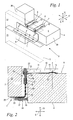
- Fig. 1 shows a perspective view of a portion of a building wall 2, which comprises a support wall 4 and arranged on the outside of the building at a distance from the support wall 4, indicated by dashed lines 3.
- the shown section of the building wall 2 is shown in the finished upright position, in which a vertical direction is indicated by a double arrow 19 in a coordinate system, a lateral direction by a double arrow 17 and a transverse direction to the plane of the building wall 2 distance direction by a double arrow 5.
- the supporting wall 4 may be a masonry, a cast concrete wall or the like.
- There is a surface design or - as here in the embodiment shown - a version as a framework with a horizontal beam 29 and a vertical support 30 into consideration.
- the bracket anchor 1 includes in addition to the console 6 and a number of fasteners 7, by means of which the bracket 6 is fixed to the support wall 4.
- the fastening elements 7 shown here are designed as in the distance direction 5 extending armature 8.
- the anchors 8 extend in the spacing direction 5 over a horizontal surface 9 of the horizontal support 29 of the support wall 4. It may be provided attachment of the armature 8, for example on a lower-side horizontal surface of the support wall 4 in particular in the region of a fall.
- the anchors 8 extend above the horizontal surfaces 9 of the support wall 4 in the direction of spacing 5 and lie with respect to the vertical direction 19 from above on the horizontal surface 9.
- a screw connection shown in detail in Fig. 2 is provided for fastening the armature 8 on the horizontal surface 9. It may also be expedient to fasten the anchor 10 by masonry bricked up from above or else to provide a clamping connection with the horizontal beam 29.
- the illustration of FIG. 1 can still be seen that the armature 8 than on the horizontal surface 9 in the distance direction 5 protruding Krag element is executed, which is formed in the embodiment shown as an angled profile in cross-section, here as upwardly open U-profile 10. It can also be a hollow profile or anchor with solid cross section appropriate.
- the bracket 6 has at least two attachment points 16 for each one anchor 8, which are related to the intended and shown here in Fig. 1 mounting position in the side direction 17 to each other at a distance.
- at least three, as in the embodiment shown here, or a plurality of mutually in the lateral direction 17 mutually spaced attachment points 16 are provided for each anchor 8.
- the respective connection between the bracket 6 and the armature 8 is in the region of the associated attachment point 16 solvable, with details of the releasable connection in connection with FIG. 2 are described in more detail.
- the detachable connection allows in the manner of a modular system, not to provide each of the attachment points 16, each with an anchor 8. According to the illustration according to FIG.
- an armature 8 is connected to the console 6 only at a middle and an outer attachment point 16, while no armature 8 is provided at the remaining outer attachment point 16. This allows an overhanging in the lateral direction 17 arrangement of the console 6 in the region of the vertical support 30, in which no suitable horizontal horizontal surface 9 is available for attachment.
- the console 6 may be walled in between the lower element 31 and the upper element 32.
- the veneer 3 in metal, plastic or the like.
- the attachment point 16 of the armature 8 on the console 6 is formed in the illustrated embodiment by an arrangement comprising a screw in the vertical direction 19 shown in the mounting position shown here screw 18 and a coaxially aligned threaded sleeve 21.
- the threaded sleeve 21st is, as is apparent from the synopsis with the perspective view of FIG. 1, inserted into a recess of a running in the vertical direction 19 leg 24 of the console 6 and welded to it firmly.
- the bolt 18 is screwed with a lower end 20 in the threaded sleeve 21 of the console 6 and can be unscrewed from her, if necessary.
- FIG. 2 The cross-sectional view of FIG. 2 can be seen in conjunction with the perspective view of FIG. 1 that the bracket 6 is formed by an angled plate with two flat legs 23, 24, wherein the first leg 23 in the direction of distance 5 and the Side direction 17 and the second leg 24 in the side direction 17 and the vertical direction 19 extends.
- the two elements 31, 32 of the veneer 3 can be moved relative to the lower leg 23 in the lateral direction 17 as desired.
- An exact alignment of the bracket anchor 1 in the side direction 17 is not required.
- the angled sheet metal of the console 6 is designed as a single bent bent part. It may also be appropriate to use a rolled L-profile or a welded construction.
- the distance of the support portion 25 to the support wall 4 is adjustable in the distance direction 5 in the embodiment shown by means of the spacer 26.
- a threaded sleeve 27 extending in the direction of spacing 5 is welded on the underside of the support section 25, into which a support screw 28 is screwed.
- the support screw 28 rests with its head on the outside of the vertical surface of the support wall 4 and prevents compression of the support portion 25 inwards / downwards.
- the distance of the support portion 25 to the support wall 4 is adjustable and, if necessary, also nachaufierbar with attached upper element 32.
- FIG. 3 shows a front view of the arrangement according to FIGS. 1 and 2, in which it can be seen that the two related to a respective attachment point 16 with the console 6 anchors 8 rest on the vertical direction 19 from above on the horizontal surface 9 of the horizontal beam 29.
- the two anchors 8 are connected by means of the screwed into the threaded sleeves 21 bolts 18 with the console 6. With the lying in the region of the vertical support 30 threaded sleeve 21 no anchor 8 is screwed.
- a threaded sleeve 27 for a respective spacer 26 is arranged in alignment beneath each threaded sleeve 21.
- the plan view of the arrangement according to the invention shown in FIG. 4 it can be seen that the threaded sleeves 21 are welded lying to secure the anchor 8 in the plane of the second leg 24.
- the elongated holes 12 extend parallel to the longitudinal direction 11 of the U-profiles 10 forming the armatures 8.
- the bottom region of the U-profiles 10 is provided with a latching surface structure 13 around the oblong holes 12, which in the exemplary embodiment shown as corrugations extending at right angles to the longitudinal direction 11 is executed.
- the detent plates 14 have on their side facing the surface structure 13 on a non-illustrated latching form which engages latching in the surface structure 13 and thus prevents slippage of the armature 8 in the longitudinal direction 11 and the spacing direction 5.
Landscapes
- Engineering & Computer Science (AREA)
- Architecture (AREA)
- Civil Engineering (AREA)
- Structural Engineering (AREA)
- Joining Of Building Structures In Genera (AREA)
- Supports Or Holders For Household Use (AREA)
- Ladders (AREA)
- Finishing Walls (AREA)
- Load-Bearing And Curtain Walls (AREA)
Abstract
Description
- Die Erfindung betrifft einen Konsolanker für eine Gebäudewand, vorgesehen zur Fixierung einer Verblendung an einer Tragwand, mit den Merkmalen nach dem Oberbegriff des Anspruchs 1.
- Wände von Gebäuden umfassen in bekannter Bauweise eine Tragwand, die auf ihrer Außenseite mit einer Verblendung versehen ist. Die beispielsweise gemauerte oder aus Beton gegossene Tragwand ist nach Gesichtspunkten der Statik ausgelegt, während die auf der Gebäudeaußenseite angeordnete Verblendung das optische Erscheinungsbild prägen soll. Die Verblendung kann ein einwandiges Sichtmauerwerk, eine Metallkonstruktion oder dgl. sein und weist eine nur eingeschränkte statische Belastbarkeit auf. Insbesondere bei höheren Bauwerken ist deshalb in vorgeschriebenen Höhenabständen eine mechanische Verbindung der Verblendung mit der Tragwand erforderlich, um eine in sich ausgesteifte, tragfähige Konstruktion zu gewährleisten.
- Zur Verbindung zwischen der Verblendung und der Tragwand sind sogenannte Konsolanker bekannt, die an der Tragwand befestigt werden. Eine etwa horizontal ausgerichtete Konsole des Konsolankers trägt einzelne Elemente der Verblendung, die auf der Konsole aufliegen. Durch eine entsprechende Befestigung zwischen dem Verblendungselement und der Konsole erzeugt der Konsolanker in der horizontalen Abstandsrichtung eine Abstützung der Verblendung gegen die Tragwand. Geeignete Befestigungspunkte für die Konsolanker sind durch die Geometrie der Tragwand und der Verblendungselemente vorgegeben, die nicht immer in Flucht zueinander liegen. Für eine exakte Ausrichtung der Verblendungselemente gegenüber der Tragwand sind entsprechend einstellbare Konsolanker vorgesehen.
- Aus der
DE 77 14 716 und derDE 37 43 701 A1 sind jeweils lageverstellbare Konsolanker bekannt, die mittels Einstellschrauben, gegebenenfalls in Verbindung mit einer vertikalen Führungsschiene in ihrer Höhe einstellbar sind. Als Befestigungselement für die Tragwand dient jeweils eine horizontal angeordnete, im Querschnitt etwa C-förmig ausgebildete Montageschiene, die horizontal eingemauert bzw. in Beton eingegossen wird. In eine solche horizontale Montageschiene lassen sich ein oder mehrere Konsolanker einsetzen und in der horizontalen Querrichtung ausrichten. Die entsprechend ausgeführten Konsolanker sind konstruktiv aufwendig und kostspielig. Der horizontal ausgerichtete Einbau der Montageschiene durch Einmauern oder Eingießen erfordert an der Baustelle erheblichen Aufwand, dem noch Justierarbeiten an den einzelnen Konsolankern folgen. - Der Erfindung liegt die Aufgabe zugrunde, einen Konsolanker der eingangs beschriebenen Gattung derart weiterzubilden, daß bei vereinfachtem Aufbau eine erleichterte Montage möglich ist.
- Die Aufgabe wird durch einen Konsolanker mit den Merkmalen des Anspruchs 1 gelöst.
- Es wird ein Konsolanker vorgeschlagen, bei dem das Befestigungselement zur Befestigung an der Tragwand als in der Abstandsrichtung verlaufender Anker ausgeführt ist, der zur Befestigung mit einer horizontalen Fläche der Tragwand vorgesehen ist. Im montierten Zustand verläuft der Anker mit seiner Längsachse quer zur Ebene der Gebäudewand in der Abstandsrichtung und übergreift dabei die horizontale Fläche. Als horizontale Fläche kann die Unterseite beispielsweise eines Sturzes vorgesehen sein. Insbesondere verläuft der Anker oberhalb einer horizontalen Fläche der Tragwand in der Abstandsrichtung und ist zur Befestigung von oben an der horizontalen Fläche vorgesehen. Nach Fertigstellung der Tragwand wird der Anker einfach auf eine obere, freiliegende horizontale Fläche aufgelegt, wobei schon in diesem Zustand eine Gewichtskraftabstützung als Sicherung gegen Herabfallen gegeben ist. Eine abschließende Fixierung erfolgt insbesondere durch eine vertikal in die horizontale Fläche eingedrehte Befestigungsschraube. Der Anker kann aber auch eingemauert oder in anderer Weise befestigt werden. Die Baueinheit aus Konsole und Anker, die den Konsolanker bildet, ist einfach im Aufbau. Eine Ausrichtung in Abstandsrichtung ist ebenso einfach möglich, wie in Seiten- und Vertikalrichtung. In Seiten- und Abstandsrichtung kann eine Grobausrichtung, gegebenenfalls auch eine Feinausrichtung allein durch manuelles Verschieben des Ankers auf der horizontalen Fläche der Tragwand erfolgen.
- In bevorzugter Weiterbildung ist der Anker als im Querschnitt abgewinkeltes Profil und insbesondere als offenes U-Profil ausgebildet. Bei geringem Gewicht- und Materialeinsatz ist eine hohe Tragfähigkeit insbesondere in Vertikalrichtung gegeben. Die Ausbildung als offenes U-Profil erlaubt außerdem eine flächige Anlage an der horizontalen Montagefläche der Tragwand und eine feste Verschraubung mit dieser, ohne daß Querschnittsverformungen des Ankers befürchtet werden müssen.
- Der Anker weist zweckmäßig ein in seiner Längsrichtung verlaufendes Langloch zur Verschraubung mit der horizontalen Fläche auf. Bei nicht ganz festgezogener Befestigungsschraube erlaubt das Langloch eine manuelle Feinjustierung der Lage des Konsolankers in Abstandsrichtung. Insbesondere ist hierzu im Bereich des Langloches eine rastende Oberflächenstruktur zur Anlage mit einer Rastplatte vorgesehen, wobei die Befestigungsschraube durch die Rastplatte und das Langloch hindurchgeführt und mit der horizontalen Fläche verschraubt ist. Die Rastplatte wirkt als Unterlegscheibe für den Kopf der Befestigungsschraube, wobei die rastende Oberflächenstruktur im festgezogenen Zustand der Befestigungsschraube ein Verrutschen in der Abstandsrichtung verhindert.
- In einer bevorzugten Ausführung weist die Konsole mindestens zwei Befestigungspunkte für je einen Anker auf, die bezogen auf die vorgesehene Einbaulage in der Seitenrichtung zueinander mit Abstand liegen. Die Konsole kann entsprechend breit ausgeführt sein, wobei die mindestens zwei Anker eine einfache horizontale Ausrichtung ermöglichen. Insbesondere sind mindestens drei in der Seitenrichtung zueinander mit Abstand liegende Befestigungspunkte für je einen Anker vorgesehen, wobei die jeweilige Verbindung zwischen der Konsole und dem Anker im Bereich des zugeordneten Befestigungspunktes lösbar ist. Am Beispiel eines gegossenen Formteiles der Gebäudewand mit Horizontal- und Vertikalträgern wird deutlich, daß eine horizontale Montagefläche am Horizontalträger für den Konsolanker dort nicht zur Verfügung steht, wo der Vertikalträger nach oben herausragt. Sofern der erfindungsgemäße Konsolanker im Bereich solcher oder anderer geometrisch komplexer Tragwandabschnitte montiert werden soll, können nach dem Baukastenprinzip einzelne Anker an der Konsole befestigt bzw. von ihr abgenommen werden. Dies erlaubt die Befestigung von breiteren Konsolen mit mehreren Ankern in Bereichen, bei denen eine entsprechend ausgerichtete, durchgehende horizontale Montagefläche nicht zur Verfügung steht.
- Bevorzugt ist der Befestigungspunkt durch einen Schraubbolzen gebildet, der bezogen auf die vorgesehene Einbaulage in einer Vertikalrichtung verläuft, mit einem Ende in eine Gewindehülse der Konsole eingeschraubt und mit einem gegenüberliegenden Ende mit dem Anker verschraubt ist. Der Schraubbolzen läßt sich mit geringem Aufwand in die Gewindehülse ein- oder aus ihr herausdrehen, wodurch einzelne Anker in geeigneter Anzahl in einfacher Weise an den entsprechenden Befestigungspunkten der Konsole angebracht werden können. Die Verschraubung am gegenüberliegenden Ende mit dem Anker ermöglicht eine einfache Höhenjustierung.
- In einer bevorzugten Ausführung ist die Konsole durch ein abgewinkeltes Blech mit zwei ebenen Schenkeln gebildet, wobei sich der erste Schenkel in der Abstandsrichtung und der Seitenrichtung und der zweite Schenkel in der Seitenrichtung und der Vertikalrichtung erstreckt. Das abgewinkelte Blech kann einstückig gebogen, als gewalztes Profil oder als verschweißte Blechkonstruktion ausgeführt sein und ermöglicht durch den Verzicht auf in Abstands- und Vertikalrichtung verlaufende Aussteifungen eine beliebige horizontale Verschiebbarkeit des aufzusetzenden Verblendungselementes. Das Genauigkeitserfordernis zur Ausrichtung des Konsolankers in der Seitenrichtung ist verringert.
- Die Konsole ist vorteilhaft im Bereich eines insbesondere durch den ersten Schenkel gebildeten Tragabschnittes mittels eines Abstandshalters gegen die Tragwand abgestützt. Dabei ist zweckmäßig der Abstand des Tragabschnittes zur Tragwand mittels des Abstandshalters einstellbar, wobei insbesondere eine in der Abstandsrichtung verlaufende Gewindehülse am Tragabschnitt vorgesehen ist, in die eine an der Tragwand anliegende Stützschraube eingedreht ist. Bei Belastung des Konsolankers durch das aufgesetzte Verblendungselement in Gewichtskraftrichtung vermeidet der Abstandshalter ein schwenkendes, nach unten und innen gerichtetes Durchfedern der Konsole. Die direkte und unmittelbare Abstützung gegen das Mauerwerk ist wirkungsvoll und konstruktiv einfach im Aufbau.
- Die Einstellbarkeit erlaubt auch im bereits montierten Zustand eine Nachjustierung.
- In bevorzugter Weiterbildung ist bezogen auf die Vertikalrichtung unterhalb der Befestigungspunkte je ein Abstandshalter angeordnet. Die in Vertikalrichtung fluchtende Anordnung von Befestigungspunkt und Abstandshalter erzeugt in diesem Bereich eine symmetrische Krafteinleitung, die ein lastbedingtes seitliches Ausweichen der Konsole verhindert. Nach dem oben beschriebenen Baukastensystem kann jedem der zur Montage erforderlichen und vorgesehenen Anker je ein Abstandshalter zugeordnet werden, während im Bereich unbesetzter Befestigungspunkte zur Beibehaltung der symmetrischen Krafteinleitung auch der entsprechende Abstandshalter nicht eingesetzt wird.
- Ein Ausführungsbeispiel der Erfindung ist im folgenden anhand der Zeichnung näher beschrieben. Es zeigen:
- Fig. 1
- in einer perspektivischen Übersichtsdarstellung einen Abschnitt einer Gebäudewand mit einer Tragwand, einer Verblendung und einem erfindungsgemäß ausgeführten Konsolanker zur Verbindung der beiden,
- Fig. 2
- eine Querschnittsdarstellung der Anordnung nach Fig. 1 mit konstruktiven Einzelheiten des Konsolankers und dessen von oben mit einer horizontalen Fläche der Tragwand verschraubten Ankers,
- Fig. 3
- eine Frontansicht der Anordnung nach den Fig. 1 und 2 mit Einzelheiten zu zwei exzentrisch angeordneten Ankern und je einem in Vertikalrichtung dazu fluchtenden Abstandshalter,
- Fig. 4
- eine Draufsicht der vorgenannten Anordnung mit Details einer Langlochverschraubung der Anker mit der Tragwand,
- Fig. 5
- eine perspektivische Darstellung des Konsolankers nach Fig. 1 in abgewandelter Konfiguration mit zwei symmetrisch in Seitenrichtung angeordneten Ankern.
- Fig. 1 zeigt in einer perspektivischen Ansicht einen Abschnitt einer Gebäudewand 2, die eine Tragwand 4 und eine auf der Gebäudeaußenseite mit Abstand zur Tragwand 4 angeordnete, gestrichelt angedeutete Verblendung 3 umfaßt. Der gezeigte Abschnitt der Gebäudewand 2 ist in fertig aufgerichteter Lage dargestellt, bei der in einem Achsenkreuz eine Vertikalrichtung durch einen Doppelpfeil 19, eine Seitenrichtung durch einen Doppelpfeil 17 und eine quer zur Ebene der Gebäudewand 2 liegende Abstandsrichtung durch einen Doppelpfeil 5 angegeben ist. Die Tragwand 4 kann ein Mauerwerk, eine gegossene Betonwand oder dgl. sein. Es kommt eine flächige Ausführung oder - wie hier im gezeigten Ausführungsbeispiel - eine Ausführung als Rahmenwerk mit einem Horizontalträger 29 und einem Vertikalträger 30 in Betracht. Die flächige, im Vergleich zur Tragwand 4 dünnwandige Verblendung 3 kann ein Sichtmauerwerk beispielsweise aus Ziegeln oder dgl. sein oder aus Metall- bzw. Glaselementen oder dgl. aufgebaut sein. Im gezeigten Ausführungsbeispiel umfaßt die Verblendung 3 ein unteres Element 31 und ein oberes Element 32, die in der Vertikalrichtung 19 einen geringen Abstand zueinander aufweisen. In diesem Abstand liegt ein Schenkel einer im Querschnitt L-förmigen Konsole 6, die Teil eines Konsolankers 1 ist. Die Verblendung 3 ist mittels des Konsolankers 1 in der Abstandsrichtung 5 gegen die Tragwand 4 abgestützt. Darüber hinaus ist der Konsolanker 1 in der Lage, zumindest einen Teil der Gewichtskräfte der Verblendung 3 gegen die Tragwand 4 abzustützen.
- Der Konsolanker 1 umfaßt neben der Konsole 6 auch eine Anzahl von Befestigungselementen 7, mittels derer die Konsole 6 an der Tragwand 4 befestigt ist. Nach der Erfindung ist vorgesehen, daß die hier gezeigten Befestigungselemente 7 als in der Abstandsrichtung 5 verlaufende Anker 8 ausgeführt sind. Die Anker 8 erstrecken sich in der Abstandsrichtung 5 über eine horizontale Fläche 9 des Horizontalträgers 29 der Tragwand 4. Es kann eine Befestigung der Anker 8 beispielsweise an einer unterseitigen Horizontalfläche der Tragwand 4 insbesondere im Bereich eines Sturzes vorgesehen sein. Im gezeigten, bevorzugten Ausführungsbeispiel verlaufen die Anker 8 oberhalb der horizontalen Flächen 9 der Tragwand 4 in der Abstandsrichtung 5 und liegen bezogen auf die Vertikalrichtung 19 von oben auf der horizontalen Fläche 9 auf. Zur Befestigung der Anker 8 an der horizontalen Fläche 9 ist eine in Fig. 2 näher gezeigte Verschraubung vorgesehen. Es kann auch zweckmäßig sein, die Anker 10 durch ein von oben aufgemauertes Mauerwerk zu befestigen oder auch eine Klemmverbindung mit dem Horizontalträger 29 vorzusehen. Der Darstellung nach Fig. 1 ist noch zu entnehmen, daß der Anker 8 als über die horizontale Fläche 9 in der Abstandsrichtung 5 überstehender Kragelement ausgeführt ist, das im gezeigten Ausführungsbeispiel als im Querschnitt abgewinkeltes Profil, hier als nach oben offenes U-Profil 10 ausgebildet ist. Es kann auch ein Hohlprofil oder ein Anker mit massivem Querschnitt zweckmäßig sein.
- Nach einer bevorzugten Ausführung ist vorgesehen, daß die Konsole 6 mindestens zwei Befestigungspunkte 16 für je einen Anker 8 aufweist, die bezogen auf die vorgesehene und hier in Fig. 1 gezeigte Einbaulage in der Seitenrichtung 17 zueinander mit Abstand liegen. Zweckmäßig sind mindestens drei, wie im hier gezeigten Ausführungsbeispiel, oder mehrere in der Seitenrichtung 17 zueinander mit Abstand liegende Befestigungspunkte 16 für je einen Anker 8 vorgesehen. Die jeweilige Verbindung zwischen der Konsole 6 und dem Anker 8 ist im Bereich des zugeordneten Befestigungspunktes 16 lösbar, wobei Einzelheiten der lösbaren Verbindung im Zusammenhang mit Fig. 2 näher beschrieben sind. Die lösbare Verbindung erlaubt nach Art eines Baukastens, nicht jeden der Befestigungspunkte 16 mit je einem Anker 8 zu versehen. Entsprechend der Darstellung nach Fig. 1 sind nur an einem mittleren und einem äußeren Befestigungspunkt 16 je ein Anker 8 mit der Konsole 6 verbunden, während an dem verbleibenden äußeren Befestigungspunkt 16 kein Anker 8 vorgesehen ist. Dies erlaubt eine in der Seitenrichtung 17 überkragende Anordnung der Konsole 6 in den Bereich des Vertikalträgers 30, in dem keine zur Befestigung geeignete horizontale Fläche 9 verfügbar ist.
- Bei einer Ausführung der Verblendung 3 als Sichtmauerwerk kann die Konsole 6 zwischen dem unteren Element 31 und dem oberen Element 32 eingemauert sein. Insbesondere bei Ausführungen der Verblendung 3 in Metall, Kunststoff oder dgl. kann auch eine Verschraubung oder ein andere Verbindung der Konsole 6 mit der Verblendung 3 zweckmäßig sein.
- Fig. 2 zeigt eine Querschnittsdarstellung der Anordnung nach Fig. 1, bei der eine untere Wand des den Anker 8 bildenden U-Profils 10 flächig auf der oberen horizontalen Fläche 9 aufliegt. Der Anker kragt mit geringem Überstand über die horizontale Fläche 9 in der Abstandsrichtung 5 in den Zwischenraum zwischen der Tragwand 4 und der Verblendung 3 über. Im Bereich eines gegenüberliegenden Endes ist ein der horizontalen Fläche 9 zugewandter Boden des U-Profils mit einem in einer Längsrichtung 11 des Ankers 8 verlaufenden Langloch 12 versehen, welches durch eine Rastplatte 14 abgedeckt ist. Eine angedeutete, in der Vertikalrichtung 19 verlaufende Befestigungsschraube 15 ist durch ein nicht dargestelltes zylindrisches Loch der Rastplatte 14 und das Langloch 12 hindurchgeführt und in der Vertikalrichtung 19 in die Tragwand 4 eingeschraubt. Unter Zwischenlage der Rastplatte 14 ist damit der Anker 8 mit der Tragwand 4 auf deren oberseitiger horizontaler Fläche 9 verschraubt.
- Der Befestigungspunkt 16 des Ankers 8 an der Konsole 6 ist im gezeigten Ausführungsbeispiel durch eine Anordnung gebildet, die einen in der hier gezeigten Einbaulage in der Vertikalrichtung 19 verlaufenden Schraubbolzen 18 und eine koaxial dazu ausgerichtete Gewindehülse 21 umfaßt. Die Gewindehülse 21 ist, wie sich aus der Zusammenschau mit der perspektivischen Darstellung nach Fig. 1 ergibt, in eine Ausnehmung eines in der Vertikalrichtung 19 verlaufenden Schenkels 24 der Konsole 6 eingesetzt und mit diesem fest verschweißt. Der Schraubbolzen 18 ist mit einem unteren Ende 20 in die Gewindehülse 21 der Konsole 6 eingeschraubt und kann bedarfsweise aus ihr herausgeschraubt werden. Am gegenüberliegenden Ende 22 ist der Schraubbolzen 18 durch eine Bohrung des Ankers 8 hindurchgeführt, wobei der Boden des U-Profils 10 zwischen zwei auf das Ende 22 aufgeschraubte Muttern 33 gehalten ist. Durch Drehung der Muttern 33 ist die Konsole 6 des Konsolankers 1 in ihrer Höhe relativ zum Anker und damit zur horizontalen Fläche 9 einstellbar. Durch gegenseitiges Festziehen der beiden Muttern 33 wird diese eingestellte Höhenlage bezogen auf die Vertikalrichtung 19 festgelegt.
- Der Querschnittsdarstellung nach Fig. 2 ist in Verbindung mit der perspektivischen Darstellung nach Fig. 1 zu entnehmen, daß die Konsole 6 durch ein abgewinkeltes Blech mit zwei ebenen Schenkeln 23, 24 gebildet ist, wobei sich der erste Schenkel 23 in der Abstandsrichtung 5 und der Seitenrichtung 17 und der zweite Schenkel 24 in der Seitenrichtung 17 und der Vertikalrichtung 19 erstreckt. Die beiden Elemente 31, 32 der Verblendung 3 können relativ zum unteren Schenkel 23 in der Seitenrichtung 17 beliebig verschoben werden. Eine exakte Ausrichtung des Konsolankers 1 in der Seitenrichtung 17 ist nicht erforderlich. Im gezeigten Ausführungsbeispiel ist das abgewinkelte Blech der Konsole 6 als einteilig gebogenes Biegeteil ausgeführt. Es kann auch ein gewalztes L-Profil oder eine Schweißkonstruktion zweckmäßig sein.
- Entsprechend der Darstellung nach Fig. 2 ist nur das auf dem ersten Schenkel 23 aufliegende obere Element 32 der Verblendung 3 gezeigt. Der erste Schenkel 23 bildet einen Tragabschnitt 25 für das obere Element 32, welches den ersten Schenkel 23 bzw. den Tragabschnitt 25 durch sein Eigengewicht in der Vertikalrichtung 19 belastet. Dabei wirkt der Befestigungspunkt 16 als elastischer Drehpunkt, um den der erste Schenkel 23 dazu neigt, eine nach unten und in Richtung der Tragwand 4 gerichtete Ausweichverformung auszuführen. Zur Abstützung gegen diese Verformung ist die Konsole 6 im Bereich des ersten Schenkels 23 mittels eines Abstandshalters 26 in der Abstandsrichtung 5 gegen die Tragwand 4 abgestützt.
- Der Abstand des Tragabschnittes 25 zur Tragwand 4 ist in der Abstandsrichtung 5 beim gezeigten Ausführungsbeispiel mittels des Abstandshalters 26 einstellbar. Hierzu ist unterseitig des Tragabschnittes 25 eine in der Abstandsrichtung 5 verlaufende Gewindehülse 27 angeschweißt, in die eine Stützschraube 28 eingedreht ist. Die Stützschraube 28 liegt mit ihrem Kopf außenseitig an der Vertikalfläche der Tragwand 4 an und verhindert ein Einfedern des Tragabschnittes 25 nach innen/unten. Durch Drehung der Stützschraube 28 in der Gewindehülse 27 ist der Abstand des Tragabschnittes 25 zur Tragwand 4 einstellbar und gegebenenfalls auch bei aufgesetztem oberen Element 32 nachjustierbar.
- Fig. 3 zeigt eine Frontansicht der Anordnung nach den Fig. 1 und 2, in der zu erkennen ist, daß die beiden an je einem Befestigungspunkt 16 mit der Konsole 6 verbundenen Anker 8 bezogen auf die Vertikalrichtung 19 von oben auf der horizontalen Fläche 9 des Horizontalträgers 29 aufliegen. An den beiden zugeordneten Befestigungspunkten 16 sind die beiden Anker 8 mittels der in die Gewindehülsen 21 eingedrehten Schraubbolzen 18 mit der Konsole 6 verbunden. Mit der im Bereich des Vertikalträgers 30 liegenden Gewindehülse 21 ist kein Anker 8 verschraubt. Bezogen auf die vertikalrichtung 19 ist fluchtend unterhalb jeder Gewindehülse 21 je eine Gewindehülse 27 für je einen Abstandshalter 26 angeordnet. Nur in diejenigen Gewindehülsen 27, die direkt unterhalb eines Ankers 8 liegen, ist je ein Abstandshalter 26 eingeschraubt. Die Gewindehülse 27 im Bereich des Vertikalträgers 30 bleibt ebenso frei wie die Gewindehülse 21 für einen optional anzubringenden, hier jedoch nicht befestigten Anker 8.
- Der Draufsicht der erfindungsgemäßen Anordnung nach Fig. 4 ist zu entnehmen, daß die Gewindehülsen 21 zur Befestigung der Anker 8 in der Ebene des zweiten Schenkels 24 liegend eingeschweißt sind. Parallel zur Längsrichtung 11 der die Anker 8 bildenden U-Profile 10 verlaufen die Langlöcher 12. Der Bodenbereich der U-Profile 10 ist rings um die Langlöcher 12 mit einer rastenden Oberflächenstruktur 13 versehen, die im gezeigten Ausführungsbeispiel als rechtwinklig quer zur Längsrichtung 11 verlaufende Riffelung ausgeführt ist. Die Rastplatten 14 weisen auf ihrer der Oberflächenstruktur 13 zugewandten Seite eine nicht näher dargestellte Rastform auf, die rastend in die Oberflächenstruktur 13 eingreift und damit ein Verrutschen der Anker 8 in der Längsrichtung 11 bzw. der Abstandsrichtung 5 verhindert.
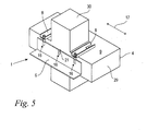
- Zur Demonstration des nach der Erfindung vorgesehenen Baukastensystems ist der im Zusammenhang mit den Fig. 1 bis 4 beschriebene Konsolanker 1 entsprechend der perspektivischen Darstellung nach Fig. 5 mit einer alternativen Ausführung der Tragwand 4 verschraubt, demnach sich der Horizontalträger 29 beidseitig zum Vertikalträger 30 erstreckt. Der Konsolanker 1 ist derart angebracht, daß die Konsole 6 in der Seitenrichtung 17 beidseitig den Vertikalträger 30 überspannt. In dieser Konfiguration ist die Gewindehülse 21 des mittleren Befestigungspunktes 16 leer, während an den beiden äußeren Befestigungspunkten 16 je ein Anker 8 angebracht ist. Die beiden Anker 8 liegen beidseitig des Vertikalträgers 30 auf der horizontalen Fläche 9 des Horizontalträgers 29 auf. Es kann auch zweckmäßig sein, Konsolen 6 in erfindungsgemäßer Weise mit einer größeren Anzahl von Befestigungspunkten 16 zu versehen, die eine variable Anpassung an unterschiedliche Ausgestaltungen von verfügbaren horizontalen Flächen 9 ermöglichen. Ebenso kann es zweckmäßig sein, eine kleinere Konsole 6 mit nur einem Befestigungspunkt 16 vorzusehen.
Claims (12)
- Konsolanker (1) für eine Gebäudewand (2), vorgesehen zur Fixierung einer Verblendung (3) an einer Tragwand (4), wobei die Verblendung (3) in einer Abstandsrichtung (5) vor der Tragwand (4) angeordnet ist, und wobei der Konsolanker (1) eine Konsole (6) zur Verbindung mit der Verblendung (3) und ein Befestigungselement (7) zur Befestigung an der Tragwand (4) aufweist,
dadurch gekennzeichnet, daß das Befestigungselement (7) als in der Abstandsrichtung (5) verlaufender Anker (8) ausgeführt ist, der zu Befestigung mit einer horizontalen Fläche (9) der Tragwand (4) vorgesehen ist. - Konsolanker nach Anspruch 1,
dadurch gekennzeichnet, daß der Anker (8) oberhalb der horizontalen Fläche (9) der Tragwand (4) in der Abstandsrichtung (5) verläuft und zur Befestigung von oben an der horizontalen Fläche (9) vorgesehen ist. - Konsolanker nach Anspruch 1 oder 2,
dadurch gekennzeichnet, daß der Anker (8) als im Querschnitt abgewinkeltes Profil und insbesondere als offenes U-Profil (10) ausgebildet ist. - Konsolanker nach einem der Ansprüche 1 bis 3,
dadurch gekennzeichnet, daß der Anker (8) ein in seiner Längsrichtung (11) verlaufendes Langloch (12) zur Verschraubung mit der horizontalen Fläche (9) aufweist. - Konsolanker nach Anspruch 4,
dadurch gekennzeichnet, daß im Bereich des Langloches (12) eine rastende Oberflächenstruktur (13) zur Anlage mit einer Rastplatte (14) vorgesehen ist, wobei eine Befestigungsschraube (15) durch die Rastplatte (14) und das Langloch (12) hindurchgeführt und mit der horizontalen Fläche (9) verschraubt ist. - Konsolanker nach einem der Ansprüche 1 bis 5,
dadurch gekennzeichnet, daß die Konsole (6) mindestens zwei Befestigungspunkte (16) für je einen Anker (8) aufweist, die bezogen auf die vorgesehene Einbaulage in einer Seitenrichtung (17) zueinander mit Abstand liegen. - Konsolanker nach Anspruch 6,
dadurch gekennzeichnet, daß mindestens drei in der Seitenrichtung (17) zueinander mit Abstand liegende Befestigungspunkte (16) für je einen Anker (8) vorgesehen sind, wobei die jeweilige Verbindung zwischen der Konsole (6) und dem Anker (8) im Bereich des zugeordneten Befestigungspunktes (16) lösbar ist. - Konsolanker nach Anspruch 7,
dadurch gekennzeichnet, daß der Befestigungspunkt (16) durch einen Schraubbolzen (18) gebildet ist, der bezogen auf die vorgesehene Einbaulage in einer Vertikalrichtung (19) verläuft, mit einem Ende (20) in eine Gewindehülse (21) der Konsole (6) eingeschraubt und mit einem gegenüberliegenden Ende (22) mit dem Anker (8) verschraubt ist. - Konsolanker nach einem der Ansprüche 1 bis 8,
dadurch gekennzeichnet, daß die Konsole (6) durch ein abgewinkeltes Blech mit zwei ebenen Schenkeln (23, 24) gebildet ist, wobei sich der erste Schenkel (23) in der Abstandsrichtung (5) und der Seitenrichtung (17) und der zweite Schenkel (24) in der Seitenrichtung (17) und der Vertikalrichtung (19) erstreckt. - Konsolanker nach einem der Ansprüche 1 bis 9,
dadurch gekennzeichnet, daß die Konsole (6) im Bereich eines insbesondere durch den ersten Schenkel (23) gebildeten Tragabschnittes (25) mittels eines Abstandshalters (26) gegen die Tragwand (4) abgestützt ist. - Konsolanker nach Anspruch 10,
dadurch gekennzeichnet, daß der Abstand des Tragabschnittes (25) zur Tragwand (4) mittels des Abstandshalters (26) einstellbar ist, wobei insbesondere eine in der Abstandsrichtung (5) verlaufende Gewindehülse (27) am Tragabschnitt (25) vorgesehen ist, in die eine an der Tragwand (4) anliegende Stützschraube (28) eingedreht ist. - Konsolanker nach Anspruch 10 oder 11,
dadurch gekennzeichnet, daß bezogen auf die Vertikalrichtung (19) unterhalb der Befestigungspunkte (16) je ein Abstandshalter (26) angeordnet ist.
Priority Applications (5)
| Application Number | Priority Date | Filing Date | Title |
|---|---|---|---|
| DE502005008682T DE502005008682D1 (de) | 2005-10-15 | 2005-10-15 | Konsolanker zur Fixierung einer Verblendung an einer Gebäudewand |
| PT05022546T PT1785546E (pt) | 2005-10-15 | 2005-10-15 | Âncora de consola para fixação de um revestimento a uma parede de edifício |
| EP05022546A EP1785546B1 (de) | 2005-10-15 | 2005-10-15 | Konsolanker zur Fixierung einer Verblendung an einer Gebäudewand |
| AT05022546T ATE451512T1 (de) | 2005-10-15 | 2005-10-15 | Konsolanker zur fixierung einer verblendung an einer gebäudewand |
| ES05022546T ES2338013T3 (es) | 2005-10-15 | 2005-10-15 | Anclaje de mensula para una pared de edificio. |
Applications Claiming Priority (1)
| Application Number | Priority Date | Filing Date | Title |
|---|---|---|---|
| EP05022546A EP1785546B1 (de) | 2005-10-15 | 2005-10-15 | Konsolanker zur Fixierung einer Verblendung an einer Gebäudewand |
Publications (2)
| Publication Number | Publication Date |
|---|---|
| EP1785546A1 true EP1785546A1 (de) | 2007-05-16 |
| EP1785546B1 EP1785546B1 (de) | 2009-12-09 |
Family
ID=35229853
Family Applications (1)
| Application Number | Title | Priority Date | Filing Date |
|---|---|---|---|
| EP05022546A Expired - Lifetime EP1785546B1 (de) | 2005-10-15 | 2005-10-15 | Konsolanker zur Fixierung einer Verblendung an einer Gebäudewand |
Country Status (5)
| Country | Link |
|---|---|
| EP (1) | EP1785546B1 (de) |
| AT (1) | ATE451512T1 (de) |
| DE (1) | DE502005008682D1 (de) |
| ES (1) | ES2338013T3 (de) |
| PT (1) | PT1785546E (de) |
Cited By (8)
| Publication number | Priority date | Publication date | Assignee | Title |
|---|---|---|---|---|
| WO2009141093A1 (en) * | 2008-05-23 | 2009-11-26 | Coughlan Engineering (Tullamore) Ltd. | Masonry support system and method |
| CN100590274C (zh) * | 2007-10-11 | 2010-02-17 | 沈阳远大铝业工程有限公司 | 幕墙连接装置 |
| DE102010022733A1 (de) * | 2010-02-24 | 2011-08-25 | HK Balkonbau GMBH, 47119 | Thermisch getrenntes Anschlussteil für Außenbauteile an Gebäuden |
| EP3085851A1 (de) * | 2015-04-21 | 2016-10-26 | Plakabeton S.A. | Konsole und verfahren zum erstellen einer mauer mit dieser konsole |
| NL2015407B1 (en) * | 2015-09-07 | 2017-03-22 | Kuijpers Uitvoering En Advies B V | Support for a façade element. |
| CZ308318B6 (cs) * | 2018-10-29 | 2020-05-06 | ÄŚeskĂ© vysokĂ© uÄŤenĂ technickĂ© v Praze | Obvodový plášť budov obsahující obvodové dílce s upevňovacími prvky na nosnou konstrukci na budově |
| EA037213B1 (ru) * | 2019-11-05 | 2021-02-19 | Совместное Общество С Ограниченной Ответственностью "Алюминтехно" | Кронштейн и узел крепления вертикальной стойки системы навесного фасада |
| BE1029713B1 (nl) * | 2021-08-25 | 2023-03-27 | Vandenbempt Patent | Geveldrager |
Citations (9)
| Publication number | Priority date | Publication date | Assignee | Title |
|---|---|---|---|---|
| DE1784453A1 (de) * | 1968-08-09 | 1972-01-27 | Lutz Ing Buero | Vorrichtung zur Befestigung von Fassadenplatten |
| DE7714716U1 (de) | 1977-05-10 | 1977-09-15 | Beine, Karlheinz, Dipl.-Ing., 4030 Ratingen | Anker fuer das abfangen von abstand zur tragenden wandung belassenden bauelementen |
| DE3743701A1 (de) | 1987-12-19 | 1989-07-06 | Deutsche Kahneisen Gmbh West | Konsolanker |
| EP0342991A1 (de) * | 1988-05-19 | 1989-11-23 | Andrew Michael Finean | Konsolensystem |
| GB2255576A (en) * | 1991-05-10 | 1992-11-11 | Metsec Plc | Masonry support. |
| GB2288831A (en) * | 1994-04-26 | 1995-11-01 | Ancon Clark Ltd | Support assembly for brick cladding |
| EP1156170A1 (de) * | 2000-05-19 | 2001-11-21 | Sergio Zambelli | Stützvorrichtung für vorgefertigte Teile, insbesondere für Konstruktionen mit einer Metallstruktur |
| WO2004015220A1 (de) * | 2002-07-31 | 2004-02-19 | Fischerwerke Artur Fischer Gmbh & Co. Kg | Tragwerk zur befestigung von fassadenplatten an einer zwischendecke oder dgl. |
| WO2004053255A1 (es) * | 2002-12-11 | 2004-06-24 | Adell Argiles Josep Maria | Sistema de apoyo para muros de albañilería |
-
2005
- 2005-10-15 PT PT05022546T patent/PT1785546E/pt unknown
- 2005-10-15 ES ES05022546T patent/ES2338013T3/es not_active Expired - Lifetime
- 2005-10-15 EP EP05022546A patent/EP1785546B1/de not_active Expired - Lifetime
- 2005-10-15 AT AT05022546T patent/ATE451512T1/de not_active IP Right Cessation
- 2005-10-15 DE DE502005008682T patent/DE502005008682D1/de not_active Expired - Lifetime
Patent Citations (9)
| Publication number | Priority date | Publication date | Assignee | Title |
|---|---|---|---|---|
| DE1784453A1 (de) * | 1968-08-09 | 1972-01-27 | Lutz Ing Buero | Vorrichtung zur Befestigung von Fassadenplatten |
| DE7714716U1 (de) | 1977-05-10 | 1977-09-15 | Beine, Karlheinz, Dipl.-Ing., 4030 Ratingen | Anker fuer das abfangen von abstand zur tragenden wandung belassenden bauelementen |
| DE3743701A1 (de) | 1987-12-19 | 1989-07-06 | Deutsche Kahneisen Gmbh West | Konsolanker |
| EP0342991A1 (de) * | 1988-05-19 | 1989-11-23 | Andrew Michael Finean | Konsolensystem |
| GB2255576A (en) * | 1991-05-10 | 1992-11-11 | Metsec Plc | Masonry support. |
| GB2288831A (en) * | 1994-04-26 | 1995-11-01 | Ancon Clark Ltd | Support assembly for brick cladding |
| EP1156170A1 (de) * | 2000-05-19 | 2001-11-21 | Sergio Zambelli | Stützvorrichtung für vorgefertigte Teile, insbesondere für Konstruktionen mit einer Metallstruktur |
| WO2004015220A1 (de) * | 2002-07-31 | 2004-02-19 | Fischerwerke Artur Fischer Gmbh & Co. Kg | Tragwerk zur befestigung von fassadenplatten an einer zwischendecke oder dgl. |
| WO2004053255A1 (es) * | 2002-12-11 | 2004-06-24 | Adell Argiles Josep Maria | Sistema de apoyo para muros de albañilería |
Cited By (9)
| Publication number | Priority date | Publication date | Assignee | Title |
|---|---|---|---|---|
| CN100590274C (zh) * | 2007-10-11 | 2010-02-17 | 沈阳远大铝业工程有限公司 | 幕墙连接装置 |
| WO2009141093A1 (en) * | 2008-05-23 | 2009-11-26 | Coughlan Engineering (Tullamore) Ltd. | Masonry support system and method |
| US8281537B2 (en) | 2008-05-23 | 2012-10-09 | Coughlan Engineering (Tullamore) Ltd. | Masonry support system and method |
| DE102010022733A1 (de) * | 2010-02-24 | 2011-08-25 | HK Balkonbau GMBH, 47119 | Thermisch getrenntes Anschlussteil für Außenbauteile an Gebäuden |
| EP3085851A1 (de) * | 2015-04-21 | 2016-10-26 | Plakabeton S.A. | Konsole und verfahren zum erstellen einer mauer mit dieser konsole |
| NL2015407B1 (en) * | 2015-09-07 | 2017-03-22 | Kuijpers Uitvoering En Advies B V | Support for a façade element. |
| CZ308318B6 (cs) * | 2018-10-29 | 2020-05-06 | ÄŚeskĂ© vysokĂ© uÄŤenĂ technickĂ© v Praze | Obvodový plášť budov obsahující obvodové dílce s upevňovacími prvky na nosnou konstrukci na budově |
| EA037213B1 (ru) * | 2019-11-05 | 2021-02-19 | Совместное Общество С Ограниченной Ответственностью "Алюминтехно" | Кронштейн и узел крепления вертикальной стойки системы навесного фасада |
| BE1029713B1 (nl) * | 2021-08-25 | 2023-03-27 | Vandenbempt Patent | Geveldrager |
Also Published As
| Publication number | Publication date |
|---|---|
| ES2338013T3 (es) | 2010-05-03 |
| PT1785546E (pt) | 2010-01-07 |
| EP1785546B1 (de) | 2009-12-09 |
| ATE451512T1 (de) | 2009-12-15 |
| DE502005008682D1 (de) | 2010-01-21 |
Similar Documents
| Publication | Publication Date | Title |
|---|---|---|
| DE102007036368A1 (de) | Deckenschalung mit Unterstützungsmitteln für Schaltafeln | |
| EP0658666B1 (de) | Befestigungssystem für Fassadenplatten | |
| EP1785546B1 (de) | Konsolanker zur Fixierung einer Verblendung an einer Gebäudewand | |
| EP0108222A2 (de) | Traggestell | |
| DE102010006560A1 (de) | Tragvorrichtung und Schalungssystem | |
| DE102011050340B4 (de) | Randschalungselement | |
| EP3643868B1 (de) | Glasträgerkonstruktion und rahmenkonstruktion | |
| AT523944B1 (de) | Geländermodul | |
| DE3405682A1 (de) | Verlorene schalung | |
| EP2253779A2 (de) | Schalungssystem | |
| EP2378030B1 (de) | Schalungssystem | |
| EP3216942A1 (de) | Bodenaufbausystem | |
| DE9409626U1 (de) | Balkonkonstruktion | |
| DE102017206316B3 (de) | Schalungselement | |
| EP2876224A1 (de) | Als Beton-Stahl-Verbundkonstruktion ausgebildete Dach- oder Deckenplatte | |
| DE1683167C3 (de) | Wandverkleidung für Außenwände | |
| AT401788B (de) | Fassade | |
| EP1033454A2 (de) | Bauelement zur Schubbewehrung | |
| EP1887156A1 (de) | Auflagevorrichtung für einen Fertigbauteil | |
| EP1739250B1 (de) | Aufhängevorrichtung für eine Fassadenverkleidung mit Drahtgitterkörben | |
| DE202011050122U1 (de) | Randschalungselement | |
| EP4283068B1 (de) | Wandanordnung und verfahren zur herstellung einer wandanordnung | |
| EP1001112B1 (de) | Gerüst für eine Schalung zur Herstellung einer Voute | |
| DE10212978B4 (de) | Befestigungseinheit zur höhenjustierbaren Befestigung eines Ausschlussprofils für ein Befestigungs- und/oder Laufschienenprofil an einer Rohdecke und/oder Unterkonstuktion | |
| WO2000005461A1 (de) | Stahlbetonplatte und schubbewehrungselement zur schubbewehrung von stahlbetonplatten |
Legal Events
| Date | Code | Title | Description |
|---|---|---|---|
| PUAI | Public reference made under article 153(3) epc to a published international application that has entered the european phase |
Free format text: ORIGINAL CODE: 0009012 |
|
| 17P | Request for examination filed |
Effective date: 20060718 |
|
| AK | Designated contracting states |
Kind code of ref document: A1 Designated state(s): AT BE BG CH CY CZ DE DK EE ES FI FR GB GR HU IE IS IT LI LT LU LV MC NL PL PT RO SE SI SK TR |
|
| AX | Request for extension of the european patent |
Extension state: AL BA HR MK YU |
|
| RAP1 | Party data changed (applicant data changed or rights of an application transferred) |
Owner name: HALFEN GMBH |
|
| 17Q | First examination report despatched |
Effective date: 20071029 |
|
| AKX | Designation fees paid |
Designated state(s): AT BE BG CH CY CZ DE DK EE ES FI FR GB GR HU IE IS IT LI LT LU LV MC NL PL PT RO SE SI SK TR |
|
| GRAP | Despatch of communication of intention to grant a patent |
Free format text: ORIGINAL CODE: EPIDOSNIGR1 |
|
| GRAS | Grant fee paid |
Free format text: ORIGINAL CODE: EPIDOSNIGR3 |
|
| GRAA | (expected) grant |
Free format text: ORIGINAL CODE: 0009210 |
|
| AK | Designated contracting states |
Kind code of ref document: B1 Designated state(s): AT BE BG CH CY CZ DE DK EE ES FI FR GB GR HU IE IS IT LI LT LU LV MC NL PL PT RO SE SI SK TR |
|
| REG | Reference to a national code |
Ref country code: GB Ref legal event code: FG4D Free format text: NOT ENGLISH |
|
| REG | Reference to a national code |
Ref country code: CH Ref legal event code: EP |
|
| REG | Reference to a national code |
Ref country code: IE Ref legal event code: FG4D |
|
| REG | Reference to a national code |
Ref country code: PT Ref legal event code: SC4A Free format text: AVAILABILITY OF NATIONAL TRANSLATION Effective date: 20091230 |
|
| REF | Corresponds to: |
Ref document number: 502005008682 Country of ref document: DE Date of ref document: 20100121 Kind code of ref document: P |
|
| PG25 | Lapsed in a contracting state [announced via postgrant information from national office to epo] |
Ref country code: FI Free format text: LAPSE BECAUSE OF FAILURE TO SUBMIT A TRANSLATION OF THE DESCRIPTION OR TO PAY THE FEE WITHIN THE PRESCRIBED TIME-LIMIT Effective date: 20091209 Ref country code: LT Free format text: LAPSE BECAUSE OF FAILURE TO SUBMIT A TRANSLATION OF THE DESCRIPTION OR TO PAY THE FEE WITHIN THE PRESCRIBED TIME-LIMIT Effective date: 20091209 Ref country code: SE Free format text: LAPSE BECAUSE OF FAILURE TO SUBMIT A TRANSLATION OF THE DESCRIPTION OR TO PAY THE FEE WITHIN THE PRESCRIBED TIME-LIMIT Effective date: 20091209 |
|
| REG | Reference to a national code |
Ref country code: ES Ref legal event code: FG2A Ref document number: 2338013 Country of ref document: ES Kind code of ref document: T3 |
|
| LTIE | Lt: invalidation of european patent or patent extension |
Effective date: 20091209 |
|
| PG25 | Lapsed in a contracting state [announced via postgrant information from national office to epo] |
Ref country code: SI Free format text: LAPSE BECAUSE OF FAILURE TO SUBMIT A TRANSLATION OF THE DESCRIPTION OR TO PAY THE FEE WITHIN THE PRESCRIBED TIME-LIMIT Effective date: 20091209 Ref country code: PL Free format text: LAPSE BECAUSE OF FAILURE TO SUBMIT A TRANSLATION OF THE DESCRIPTION OR TO PAY THE FEE WITHIN THE PRESCRIBED TIME-LIMIT Effective date: 20091209 Ref country code: LV Free format text: LAPSE BECAUSE OF FAILURE TO SUBMIT A TRANSLATION OF THE DESCRIPTION OR TO PAY THE FEE WITHIN THE PRESCRIBED TIME-LIMIT Effective date: 20091209 |
|
| REG | Reference to a national code |
Ref country code: IE Ref legal event code: FD4D |
|
| PG25 | Lapsed in a contracting state [announced via postgrant information from national office to epo] |
Ref country code: EE Free format text: LAPSE BECAUSE OF FAILURE TO SUBMIT A TRANSLATION OF THE DESCRIPTION OR TO PAY THE FEE WITHIN THE PRESCRIBED TIME-LIMIT Effective date: 20091209 Ref country code: IE Free format text: LAPSE BECAUSE OF FAILURE TO SUBMIT A TRANSLATION OF THE DESCRIPTION OR TO PAY THE FEE WITHIN THE PRESCRIBED TIME-LIMIT Effective date: 20091209 Ref country code: RO Free format text: LAPSE BECAUSE OF FAILURE TO SUBMIT A TRANSLATION OF THE DESCRIPTION OR TO PAY THE FEE WITHIN THE PRESCRIBED TIME-LIMIT Effective date: 20091209 Ref country code: BG Free format text: LAPSE BECAUSE OF FAILURE TO SUBMIT A TRANSLATION OF THE DESCRIPTION OR TO PAY THE FEE WITHIN THE PRESCRIBED TIME-LIMIT Effective date: 20100309 Ref country code: IS Free format text: LAPSE BECAUSE OF FAILURE TO SUBMIT A TRANSLATION OF THE DESCRIPTION OR TO PAY THE FEE WITHIN THE PRESCRIBED TIME-LIMIT Effective date: 20100409 |
|
| PG25 | Lapsed in a contracting state [announced via postgrant information from national office to epo] |
Ref country code: SK Free format text: LAPSE BECAUSE OF FAILURE TO SUBMIT A TRANSLATION OF THE DESCRIPTION OR TO PAY THE FEE WITHIN THE PRESCRIBED TIME-LIMIT Effective date: 20091209 Ref country code: CZ Free format text: LAPSE BECAUSE OF FAILURE TO SUBMIT A TRANSLATION OF THE DESCRIPTION OR TO PAY THE FEE WITHIN THE PRESCRIBED TIME-LIMIT Effective date: 20091209 |
|
| PLBE | No opposition filed within time limit |
Free format text: ORIGINAL CODE: 0009261 |
|
| STAA | Information on the status of an ep patent application or granted ep patent |
Free format text: STATUS: NO OPPOSITION FILED WITHIN TIME LIMIT |
|
| PG25 | Lapsed in a contracting state [announced via postgrant information from national office to epo] |
Ref country code: GR Free format text: LAPSE BECAUSE OF FAILURE TO SUBMIT A TRANSLATION OF THE DESCRIPTION OR TO PAY THE FEE WITHIN THE PRESCRIBED TIME-LIMIT Effective date: 20100310 Ref country code: CY Free format text: LAPSE BECAUSE OF FAILURE TO SUBMIT A TRANSLATION OF THE DESCRIPTION OR TO PAY THE FEE WITHIN THE PRESCRIBED TIME-LIMIT Effective date: 20091209 |
|
| 26N | No opposition filed |
Effective date: 20100910 |
|
| PG25 | Lapsed in a contracting state [announced via postgrant information from national office to epo] |
Ref country code: DK Free format text: LAPSE BECAUSE OF FAILURE TO SUBMIT A TRANSLATION OF THE DESCRIPTION OR TO PAY THE FEE WITHIN THE PRESCRIBED TIME-LIMIT Effective date: 20091209 |
|
| PG25 | Lapsed in a contracting state [announced via postgrant information from national office to epo] |
Ref country code: MC Free format text: LAPSE BECAUSE OF NON-PAYMENT OF DUE FEES Effective date: 20101031 |
|
| REG | Reference to a national code |
Ref country code: CH Ref legal event code: PL |
|
| PG25 | Lapsed in a contracting state [announced via postgrant information from national office to epo] |
Ref country code: CH Free format text: LAPSE BECAUSE OF NON-PAYMENT OF DUE FEES Effective date: 20101031 Ref country code: LI Free format text: LAPSE BECAUSE OF NON-PAYMENT OF DUE FEES Effective date: 20101031 |
|
| REG | Reference to a national code |
Ref country code: AT Ref legal event code: MM01 Ref document number: 451512 Country of ref document: AT Kind code of ref document: T Effective date: 20101015 |
|
| PG25 | Lapsed in a contracting state [announced via postgrant information from national office to epo] |
Ref country code: AT Free format text: LAPSE BECAUSE OF NON-PAYMENT OF DUE FEES Effective date: 20101015 |
|
| PG25 | Lapsed in a contracting state [announced via postgrant information from national office to epo] |
Ref country code: HU Free format text: LAPSE BECAUSE OF FAILURE TO SUBMIT A TRANSLATION OF THE DESCRIPTION OR TO PAY THE FEE WITHIN THE PRESCRIBED TIME-LIMIT Effective date: 20100610 Ref country code: LU Free format text: LAPSE BECAUSE OF NON-PAYMENT OF DUE FEES Effective date: 20101015 |
|
| PG25 | Lapsed in a contracting state [announced via postgrant information from national office to epo] |
Ref country code: TR Free format text: LAPSE BECAUSE OF FAILURE TO SUBMIT A TRANSLATION OF THE DESCRIPTION OR TO PAY THE FEE WITHIN THE PRESCRIBED TIME-LIMIT Effective date: 20091209 |
|
| PGFP | Annual fee paid to national office [announced via postgrant information from national office to epo] |
Ref country code: ES Payment date: 20141020 Year of fee payment: 10 Ref country code: FR Payment date: 20141022 Year of fee payment: 10 Ref country code: DE Payment date: 20141022 Year of fee payment: 10 Ref country code: GB Payment date: 20141021 Year of fee payment: 10 |
|
| PGFP | Annual fee paid to national office [announced via postgrant information from national office to epo] |
Ref country code: NL Payment date: 20141021 Year of fee payment: 10 Ref country code: PT Payment date: 20141014 Year of fee payment: 10 |
|
| PGFP | Annual fee paid to national office [announced via postgrant information from national office to epo] |
Ref country code: IT Payment date: 20141028 Year of fee payment: 10 |
|
| PGFP | Annual fee paid to national office [announced via postgrant information from national office to epo] |
Ref country code: BE Payment date: 20141021 Year of fee payment: 10 |
|
| REG | Reference to a national code |
Ref country code: PT Ref legal event code: MM4A Free format text: LAPSE DUE TO NON-PAYMENT OF FEES Effective date: 20160415 |
|
| REG | Reference to a national code |
Ref country code: DE Ref legal event code: R119 Ref document number: 502005008682 Country of ref document: DE |
|
| GBPC | Gb: european patent ceased through non-payment of renewal fee |
Effective date: 20151015 |
|
| REG | Reference to a national code |
Ref country code: NL Ref legal event code: MM Effective date: 20151101 |
|
| PG25 | Lapsed in a contracting state [announced via postgrant information from national office to epo] |
Ref country code: IT Free format text: LAPSE BECAUSE OF NON-PAYMENT OF DUE FEES Effective date: 20151015 Ref country code: DE Free format text: LAPSE BECAUSE OF NON-PAYMENT OF DUE FEES Effective date: 20160503 Ref country code: GB Free format text: LAPSE BECAUSE OF NON-PAYMENT OF DUE FEES Effective date: 20151015 |
|
| REG | Reference to a national code |
Ref country code: FR Ref legal event code: ST Effective date: 20160630 |
|
| PG25 | Lapsed in a contracting state [announced via postgrant information from national office to epo] |
Ref country code: FR Free format text: LAPSE BECAUSE OF NON-PAYMENT OF DUE FEES Effective date: 20151102 Ref country code: PT Free format text: LAPSE BECAUSE OF NON-PAYMENT OF DUE FEES Effective date: 20160415 Ref country code: NL Free format text: LAPSE BECAUSE OF NON-PAYMENT OF DUE FEES Effective date: 20151101 |
|
| REG | Reference to a national code |
Ref country code: ES Ref legal event code: FD2A Effective date: 20161125 |
|
| PG25 | Lapsed in a contracting state [announced via postgrant information from national office to epo] |
Ref country code: ES Free format text: LAPSE BECAUSE OF NON-PAYMENT OF DUE FEES Effective date: 20151016 |
|
| PG25 | Lapsed in a contracting state [announced via postgrant information from national office to epo] |
Ref country code: BE Free format text: LAPSE BECAUSE OF NON-PAYMENT OF DUE FEES Effective date: 20151031 |