EP1785568A2 - Rahmen für Drehkipptür oder -fenster - Google Patents
Rahmen für Drehkipptür oder -fenster Download PDFInfo
- Publication number
- EP1785568A2 EP1785568A2 EP06123996A EP06123996A EP1785568A2 EP 1785568 A2 EP1785568 A2 EP 1785568A2 EP 06123996 A EP06123996 A EP 06123996A EP 06123996 A EP06123996 A EP 06123996A EP 1785568 A2 EP1785568 A2 EP 1785568A2
- Authority
- EP
- European Patent Office
- Prior art keywords
- door
- window frame
- cup
- slide
- shaped body
- Prior art date
- Legal status (The legal status is an assumption and is not a legal conclusion. Google has not performed a legal analysis and makes no representation as to the accuracy of the status listed.)
- Withdrawn
Links
Images




Classifications
-
- E—FIXED CONSTRUCTIONS
- E05—LOCKS; KEYS; WINDOW OR DOOR FITTINGS; SAFES
- E05D—HINGES OR SUSPENSION DEVICES FOR DOORS, WINDOWS OR WINGS
- E05D15/00—Suspension arrangements for wings
- E05D15/48—Suspension arrangements for wings allowing alternative movements
- E05D15/52—Suspension arrangements for wings allowing alternative movements for opening about a vertical as well as a horizontal axis
-
- E—FIXED CONSTRUCTIONS
- E05—LOCKS; KEYS; WINDOW OR DOOR FITTINGS; SAFES
- E05D—HINGES OR SUSPENSION DEVICES FOR DOORS, WINDOWS OR WINGS
- E05D15/00—Suspension arrangements for wings
- E05D15/48—Suspension arrangements for wings allowing alternative movements
- E05D15/52—Suspension arrangements for wings allowing alternative movements for opening about a vertical as well as a horizontal axis
- E05D15/5208—Suspension arrangements for wings allowing alternative movements for opening about a vertical as well as a horizontal axis with means for transmitting movements between vertical and horizontal sliding bars, rods or cables
-
- E—FIXED CONSTRUCTIONS
- E05—LOCKS; KEYS; WINDOW OR DOOR FITTINGS; SAFES
- E05Y—INDEXING SCHEME ASSOCIATED WITH SUBCLASSES E05D AND E05F, RELATING TO CONSTRUCTION ELEMENTS, ELECTRIC CONTROL, POWER SUPPLY, POWER SIGNAL OR TRANSMISSION, USER INTERFACES, MOUNTING OR COUPLING, DETAILS, ACCESSORIES, AUXILIARY OPERATIONS NOT OTHERWISE PROVIDED FOR, APPLICATION THEREOF
- E05Y2900/00—Application of doors, windows, wings or fittings thereof
- E05Y2900/10—Application of doors, windows, wings or fittings thereof for buildings or parts thereof
- E05Y2900/13—Type of wing
- E05Y2900/132—Doors
-
- E—FIXED CONSTRUCTIONS
- E05—LOCKS; KEYS; WINDOW OR DOOR FITTINGS; SAFES
- E05Y—INDEXING SCHEME ASSOCIATED WITH SUBCLASSES E05D AND E05F, RELATING TO CONSTRUCTION ELEMENTS, ELECTRIC CONTROL, POWER SUPPLY, POWER SIGNAL OR TRANSMISSION, USER INTERFACES, MOUNTING OR COUPLING, DETAILS, ACCESSORIES, AUXILIARY OPERATIONS NOT OTHERWISE PROVIDED FOR, APPLICATION THEREOF
- E05Y2900/00—Application of doors, windows, wings or fittings thereof
- E05Y2900/10—Application of doors, windows, wings or fittings thereof for buildings or parts thereof
- E05Y2900/13—Type of wing
- E05Y2900/148—Windows
Definitions
- the present invention relates to a frame for tilt and turn doors and windows, in particular a frame made of metal, PVC or the like, aluminium and wood, and so on.
- door and window frames of this type which can be turned open in the conventional way, or tilted open, basically comprise:
- control and operating means may comprise, in the sash, transmission means slidably mounted in the groove (one or more rods connected to one another) and designed to move closing elements (for example bolts and/or contact pins) associated with the sliding transmission element.
- corner drive and control elements of the known type, inserted between the rails of the fixed frame and the sash, designed to allow the sash to be opened by tilting, that is to say by angling the sash rail away from the fixed frame rail.
- the closing elements are combined with contact means (plugs or cup-shaped elements) made or associated on / in the fixed frame groove, which engage with the closing element present in the sash groove.
- These contact means are usually positioned close to the lower and upper end zones of the fixed frame and in intermediate zones of the fixed stile (forming a so-called “third closing point") coupled with the movable stile opposite the hinged one.
- a handle is used to operate these control means (in most cases a Cremone bolt handle) as the element for opening and closing the door or window unit.
- the handle moves by rotating to three stable positions, for opening the door or window by turning, opening it by tilting and closing it.
- Ventilation is achieved by opening the door or window frame by turning or, in most cases, by tilting, and this may create unwanted effects, such as: excessive temperature changes in the room (particularly in winter), lack of security for the room as regards the possibility of breaking and entering through the open door or window frame, since it is more likely that it can be forced when in the tilted open position, thus requiring opening times for ventilation to be minimised if no one is present in the room.
- the Applicant has designed and produced a frame for doors and windows of the tilt and turn type with another configuration, alternative to the tilted configuration, designed to allow "micro-ventilation" of the room without affecting the construction architecture or the structure of the door or window frame as a whole and also maintaining a high level of door and window security.
- the present invention achieves this aim with a frame for tilt and turn doors and windows, in particular a door or window frame comprising the technical features described in one or more of the claims herein.
- the door or window frame 1 may be made with profiles made of metal, PVC or the like, aluminium and wood, and so on, without limiting the scope of the invention.
- This door or window frame 1 basically comprises:
- the transmission means 5, of the known type may be rods 5a, drive elements 5b connected to the handle 10, corner drives 5c.
- the contact elements 7 may consist of bolts 7b and end contact pins 7c associated with the rods 5a. These elements operate in conjunction with the connecting elements 8 (for example cups 8b for housing the contact pins 7c) to determine the above-mentioned door or window frame 1 configurations.
- the door or window frame 1 comprises:
- the auxiliary connecting element 13 is associated on the second groove 9 of the fixed stile 4a opposite the hinged stiles 4.
- the closing element 7a is positioned on the corresponding movable stile 3a so that, in the door or window frame 1 closed configuration, it forms an additional closing point in conjunction with a relative fixed connecting element 8.
- the sealing means 12 comprise first seals 12a positioned on the sash 3 and second seals 12b positioned on the fixed frame 2 and, therefore in the door or window frame 1 alternative or ventilation configuration, the path for interception of the closing element 7a in the auxiliary connecting element 13 results in a distancing of the first seals 12a from the fixed frame 2 and a distancing of the sash 3 from the second seals 12b at least along an upper rail 4b and a partial section of the relative two movable stiles 4 and 4a adjacent to the upper rail 4a.
- the auxiliary connecting element 13 stably houses the closing element 7a when the handgrip 11 passes to the door or window frame 1 tilted open configuration, so as to define an alternative door or window frame 1 configuration to said tilt opening, when the means 14 are moved into an activation configuration.
- the closing element consists of a bolt 7a associated with the transmission means 5 designed to allow it to move along the first groove 6 according to the possible door or window frame 1 configurations.
- This bolt 7a operates in conjunction with a relative fixed connecting element 8a associated with the fixed stile 4a in the door or window frame 1 closed configuration to form the above-mentioned additional closing point.
- the auxiliary connecting element 13 comprises an open cup-shaped body 15 slidably associated with a first fixing base 16 integral with the second groove 9.
- the cup-shaped body 15 has shaped walls 15a and 15b forming a connecting path for the bolt 7a, with the handgrip 1 in the alternative position and the cup-shaped body 15 in the activation position, allowing the sash 3 to move into the configuration with limited distancing from the fixed frame 2.
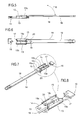
- the cup-shaped body 15 is positioned close to the fixed connecting element 8a and is connected to the activation/deactivation means 14 designed to allow it to slide between a stable non-operating position (see continuous line in Figures 9 and 15), in which the cup-shaped body 15 is distanced from the connecting element 8a, and a stable operating position (see dashed line and arrow F15 in Figures 9 and 15), in which the cup-shaped body 15 is moved close to the connecting element 8a, so that the bolt 7a can be housed in it with the passage to the alternative position.
- a stable non-operating position see continuous line in Figures 9 and 15
- a stable operating position see dashed line and arrow F15 in Figures 9 and 15
- the cup-shaped body 15 has a first section 17 of one wall 15a extending at an angle and converging towards the inside of the cup-shaped body 15 to form a guided infeed path for the bolt 7a in the cup-shaped body 15 (see arrow F7a in Figures 9 and 15) with relative limited opening stroke for the sash 3.
- a first embodiment of the activation/deactivation means 14 comprises a rod 18, pivoting at one end at the cup-shaped body 15 to allow the cup-shaped body 15 to slide, by manual pushing or pulling, between the two stable, non-operating and operating positions.
- the rod 18 also has at least one through-hole 19, on its body and which can engage with a pin 20 on the lower end of the first fixing base 16 so as to lock the rod 18 at the cup-shaped body 15 operating position.
- the rod 18 preferably has, on its body, two through holes 19 and 19a, distanced from one another, and when engaged alternatively with the pin 20, defining the cup-shaped body 15 stable, operating and non-operating positions, respectively.
- the rod 18 is housed in the second groove 9 of the fixed stile 4a, to avoid interference with the movement of the sash 3.
- the user can lift the rod 18 manually (see arrow F18 in Figure 5), detaching it from the pin 20, so as to be able to push or pull the cup-shaped body 15 (see arrow F15) in order to move it into the operating or non-operating position and, subsequently lower the rod 18 again to return it to its position along the second groove 9 and simultaneously couple it to the pin 20 in the relative hole 19 or 19a.
- the activation/deactivation means 14 comprise a slide 21 slidably associated with the second groove 9 of the fixed stile 4a.
- the slide 21 is associated at its first end with the end of the cup-shaped body 15 and, at the opposite end, it is connected to a projection 22 of a lever 23 pivoting, at 24, on both sides of a second base 25 fixed on the second groove 9.
- the lever 23 can rotate about the pivoting point 24, through an angle ⁇ , defining two stable limit positions defining a pull and, respectively, a push on the slide 21 and so defining the corresponding non-operating position ( Figures 10 and 11) and operating position of the cup-shaped body 15 (see Figures 12 and 13).
- the slide 21 has an end portion connected to the lever 23 designed to be slidably housed in the second fixing base 25 (see Figures 10 and 11).
- the lever 23 is parallel with the slide 21 and with the second fixing base 25 in its stable limit positions corresponding to the cup-shaped body 15 non-operating and operating positions, to avoid interference with the movement of the sash 3.
- the cup-shaped body 15 is slidably connected on the first guiding base 16 fixed to the second groove 9 of the fixed stile 4a as described in the previous embodiment.
- the cup-shaped body 15 has a portion of its lower part which can be partly coupled to the second groove 9 and connected there by sliding coupling means 26 (a screw), positioned centrally to the body 15, and acting between the body 15 and a lower toothed plug 27 forming a sort of auxiliary base 16 for the cup-shaped body 15.
- sliding coupling means 26 a screw
- the cup-shaped body 15 is divided into two specular portions, joined without interruptions to form two open seats 28, opposite one another, for housing the closing bolt 7a: in this way, thanks to the fixing system and this specularity, the cup-shaped body 15 can be positioned on the second groove 9 according to the type of opening (right- or left-hand) of the door or window frame 1.
- the user can move the cup-shaped body 15 from a non-operating position to the operating position (or vice versa) by rotating the lever 23.
- the user could move the handle 11 to the position originally used for opening by tilting so as to obtain, in this configuration, said limited opening of the movable stile 3 with distancing of only the seals 12 in order to achieve reduced ventilation of the room.
- the auxiliary connecting element 13 comprises a slide 113 slidably associated with a base 114 which can be fixed to the second groove 9 of the fixed stile 4a (for example with screws 114v).
- the slide 113 has two opposite ends 113a, 113b shaped so that each forms a connecting path for the bolt 7a, with the handgrip 11 in the alternative position and the slide 113 in the activation position (see Figure 18) using the activation/deactivation means 14, allowing the sash 3 configuration with limited distancing from the fixed frame 2.
- the ends 113a, 113b are opposite and specular to allow rapid and simple slide 113 mounting on the second groove 9 according to the type of opening (right- or left-hand) of the door or window frame 1.
- the activation/deactivation means 14 comprise:
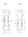
- the elastic element consists of an open spring 115 with two free ends 115a and 115b having the shape of a hook and each able to stably connect in a relative lower seat 116a, 116b in the slide 113 (clearly visible in Figures 17, 20 and 21).
- the spring 115 is also shaped to form two curved lateral portions 117 engaged in a groove 118 formed by a pair of inverted "L"-shaped wings 119 on the base 114 and in which the slide 113 also runs.
- the base 114 also has two pairs of lateral openings 120, 121 (opposite pairs) in the groove 118, corresponding to the slide 113 activation/deactivation positions, designed for engagement, on each occasion, with the curved portions 117 of the spring 115, to render the positions assumed by the slide 113 stable.
- the distance D120 between the two pairs of lateral openings 120, 121 represents the slide 113 activation or deactivation stroke: when the slide 113 is moved from one position to another or vice versa, by the user manually pushing or pulling on the central portion 113c of the slide, the spring 115 is laterally compressed and comes out of the relative pair of openings 120 or 121 (pulled by the slide 113 and visible in Figure 21) until the point where it meets the other pair of openings 121 or 120 in which the curved portions 117 engage, thus giving the new slide 113 positioning (see Figure 20).
- the slide 113 has a lower outline 113s (visible in Figure 17) designed to retain at least another portion of the spring 115, to prevent the spring 115 from moving about a vertical axis or in any case its rotational axial movement, which could stop the movement of the slide 113 along the base 114.
- FIGS 22 and 23 show an alternative embodiment of the bolt 7a which can be used with the accessories described above: this bolt 7a may have its projecting portion 122, for intercepting for example one of the above-mentioned shaped ends 113a and 113b, eccentric relative to its base 123 for fixing to the transmission element 5.
- the eccentricity of the bolt 7a allows more precise adjustment of the sash 3 micro-ventilation position without affecting its primary closing or contact functions in the other door or window frame 1 configurations.
- the door or window frame structured in this way achieves the aims thanks to a substantial fourth door or window frame operating configuration which is an alternative to the tilting configuration.
- this "micro"-ventilation accessory is such that it can even be retrofitted to existing door or window frames without having to modify any of their other accessories.
- the accessory structured in this way may advantageously be applied to the door or window frame even after the frame has been installed and without special machining and without any substitution of parts already fitted.
Landscapes
- Engineering & Computer Science (AREA)
- Mechanical Engineering (AREA)
- Specific Sealing Or Ventilating Devices For Doors And Windows (AREA)
- Wing Frames And Configurations (AREA)
Applications Claiming Priority (1)
| Application Number | Priority Date | Filing Date | Title |
|---|---|---|---|
| ITBO20050694 ITBO20050694A1 (it) | 2005-11-15 | 2005-11-15 | Serramento con apertura ad anta ed a ribalta |
Publications (2)
| Publication Number | Publication Date |
|---|---|
| EP1785568A2 true EP1785568A2 (de) | 2007-05-16 |
| EP1785568A3 EP1785568A3 (de) | 2008-10-01 |
Family
ID=37770315
Family Applications (1)
| Application Number | Title | Priority Date | Filing Date |
|---|---|---|---|
| EP06123996A Withdrawn EP1785568A3 (de) | 2005-11-15 | 2006-11-14 | Rahmen für Drehkipptür oder -fenster |
Country Status (2)
| Country | Link |
|---|---|
| EP (1) | EP1785568A3 (de) |
| IT (1) | ITBO20050694A1 (de) |
Cited By (1)
| Publication number | Priority date | Publication date | Assignee | Title |
|---|---|---|---|---|
| WO2025081796A1 (zh) * | 2023-10-17 | 2025-04-24 | 深圳好博窗控技术股份有限公司 | 传动装置及窗体 |
Citations (1)
| Publication number | Priority date | Publication date | Assignee | Title |
|---|---|---|---|---|
| WO2002014638A1 (de) | 2000-08-14 | 2002-02-21 | Siegenia-Frank Kg | Dreh-kipp-beschlag für fenster, türen od. dgl. |
Family Cites Families (2)
| Publication number | Priority date | Publication date | Assignee | Title |
|---|---|---|---|---|
| DE8123266U1 (de) * | 1981-08-07 | 1981-11-26 | Siegenia-Frank Kg, 5900 Siegen | Eckumlenkung fuer treibstangenbeschlaege von fenstern, tueren o.dgl. |
| EP1359274A1 (de) * | 2002-04-25 | 2003-11-05 | Ajs Ingenierie S.A. | Verstellbarer Lüftungsanschlag für Öffnungen |
-
2005
- 2005-11-15 IT ITBO20050694 patent/ITBO20050694A1/it unknown
-
2006
- 2006-11-14 EP EP06123996A patent/EP1785568A3/de not_active Withdrawn
Patent Citations (1)
| Publication number | Priority date | Publication date | Assignee | Title |
|---|---|---|---|---|
| WO2002014638A1 (de) | 2000-08-14 | 2002-02-21 | Siegenia-Frank Kg | Dreh-kipp-beschlag für fenster, türen od. dgl. |
Cited By (1)
| Publication number | Priority date | Publication date | Assignee | Title |
|---|---|---|---|---|
| WO2025081796A1 (zh) * | 2023-10-17 | 2025-04-24 | 深圳好博窗控技术股份有限公司 | 传动装置及窗体 |
Also Published As
| Publication number | Publication date |
|---|---|
| EP1785568A3 (de) | 2008-10-01 |
| ITBO20050694A1 (it) | 2007-05-16 |
Similar Documents
| Publication | Publication Date | Title |
|---|---|---|
| US4420905A (en) | Closure hardware | |
| JP5425198B2 (ja) | 窓の施錠装置 | |
| KR100970687B1 (ko) | 문짝과 고정 보더 사이에 제어 가능한 밀봉 요소를 구비한 슬라이딩 창호 | |
| EP4006277B1 (de) | Vorrichtung zur begrenzung der öffnung von türen oder fenstern | |
| US4339892A (en) | Safety window of the tilt and turn type | |
| US4942694A (en) | Fittings for doors, windows or the like | |
| CN1836084B (zh) | 带有至少一个辅助开启装置和阻滞装置的改进的枢转窗户 | |
| EP2617919B1 (de) | Betriebsgriff | |
| RU2225491C2 (ru) | Окно или дверь | |
| US4541200A (en) | Swing-tilt fitting for window or doors | |
| KR102147697B1 (ko) | 적어도 리프팅 되며, 바람직하게는 슬라이딩 될 수 있는 윈도우 또는 도어의 윙을 위한 피팅장치. | |
| KR20240146659A (ko) | 창문 또는 문의 윙, 특히 슬라이딩 윙의 강제 이동을 위한 이동 장치 | |
| HU223791B1 (hu) | Kétszárnyas ajtó, különösen tűzvédelmi ajtó | |
| EP1619326B1 (de) | Fehlbedienungssperre für Tür- oder Fenstergriff-Steuereinheiten. | |
| EP1785562B1 (de) | Seitlich angelenkter Flügel einer Tür oder eines Fensters | |
| KR20090131872A (ko) | 개선된 힌지부를 가지는 프로젝트 및 케이스먼트 운동이가능한 창호 | |
| EP2113623A2 (de) | Kippflügelfenstereinheit | |
| KR102304996B1 (ko) | 미닫이창용 여밈장치 | |
| BE1030136B1 (nl) | Hoekoverbrenging voor raambeslag | |
| EP2267250B1 (de) | Schliessblech für Fenster und Türen | |
| EP4545739B1 (de) | Begrenzungsanordnung zur begrenzung der öffnung einer schiebetür oder eines schiebefensters | |
| WO2026013518A1 (en) | Adjustable concealed hinge for windows with a projecting sash | |
| KR200416483Y1 (ko) | 윗 열기와 여닫이 겸용 시스템창호의 세팅수단 | |
| EP2113622A2 (de) | Bedienteil für Kippflügelfenster | |
| JP2002227512A (ja) | 平行突き出し窓 |
Legal Events
| Date | Code | Title | Description |
|---|---|---|---|
| PUAI | Public reference made under article 153(3) epc to a published international application that has entered the european phase |
Free format text: ORIGINAL CODE: 0009012 |
|
| AK | Designated contracting states |
Kind code of ref document: A2 Designated state(s): AT BE BG CH CY CZ DE DK EE ES FI FR GB GR HU IE IS IT LI LT LU LV MC NL PL PT RO SE SI SK TR |
|
| AX | Request for extension of the european patent |
Extension state: AL BA HR MK YU |
|
| PUAL | Search report despatched |
Free format text: ORIGINAL CODE: 0009013 |
|
| AK | Designated contracting states |
Kind code of ref document: A3 Designated state(s): AT BE BG CH CY CZ DE DK EE ES FI FR GB GR HU IE IS IT LI LT LU LV MC NL PL PT RO SE SI SK TR |
|
| AX | Request for extension of the european patent |
Extension state: AL BA HR MK RS |
|
| 17P | Request for examination filed |
Effective date: 20090130 |
|
| AKX | Designation fees paid |
Designated state(s): AT BE BG CH CY CZ DE DK EE ES FI FR GB GR HU IE IS IT LI LT LU LV MC NL PL PT RO SE SI SK TR |
|
| 17Q | First examination report despatched |
Effective date: 20100913 |
|
| STAA | Information on the status of an ep patent application or granted ep patent |
Free format text: STATUS: THE APPLICATION IS DEEMED TO BE WITHDRAWN |
|
| 18D | Application deemed to be withdrawn |
Effective date: 20121228 |