EP1785588B1 - Dispositif de ventilation de disque de turbine dans un moteur à turbine à gaz - Google Patents
Dispositif de ventilation de disque de turbine dans un moteur à turbine à gaz Download PDFInfo
- Publication number
- EP1785588B1 EP1785588B1 EP06122697.3A EP06122697A EP1785588B1 EP 1785588 B1 EP1785588 B1 EP 1785588B1 EP 06122697 A EP06122697 A EP 06122697A EP 1785588 B1 EP1785588 B1 EP 1785588B1
- Authority
- EP
- European Patent Office
- Prior art keywords
- turbine
- engine
- air
- spinning wheel
- disc
- Prior art date
- Legal status (The legal status is an assumption and is not a legal conclusion. Google has not performed a legal analysis and makes no representation as to the accuracy of the status listed.)
- Active
Links
Images


Classifications
-
- F—MECHANICAL ENGINEERING; LIGHTING; HEATING; WEAPONS; BLASTING
- F02—COMBUSTION ENGINES; HOT-GAS OR COMBUSTION-PRODUCT ENGINE PLANTS
- F02C—GAS-TURBINE PLANTS; AIR INTAKES FOR JET-PROPULSION PLANTS; CONTROLLING FUEL SUPPLY IN AIR-BREATHING JET-PROPULSION PLANTS
- F02C7/00—Features, components parts, details or accessories, not provided for in, or of interest apart form groups F02C1/00 - F02C6/00; Air intakes for jet-propulsion plants
- F02C7/12—Cooling of plants
-
- F—MECHANICAL ENGINEERING; LIGHTING; HEATING; WEAPONS; BLASTING
- F01—MACHINES OR ENGINES IN GENERAL; ENGINE PLANTS IN GENERAL; STEAM ENGINES
- F01D—NON-POSITIVE DISPLACEMENT MACHINES OR ENGINES, e.g. STEAM TURBINES
- F01D5/00—Blades; Blade-carrying members; Heating, heat-insulating, cooling or antivibration means on the blades or the members
- F01D5/02—Blade-carrying members, e.g. rotors
- F01D5/08—Heating, heat-insulating or cooling means
- F01D5/081—Cooling fluid being directed on the side of the rotor disc or at the roots of the blades
- F01D5/082—Cooling fluid being directed on the side of the rotor disc or at the roots of the blades on the side of the rotor disc
-
- F—MECHANICAL ENGINEERING; LIGHTING; HEATING; WEAPONS; BLASTING
- F05—INDEXING SCHEMES RELATING TO ENGINES OR PUMPS IN VARIOUS SUBCLASSES OF CLASSES F01-F04
- F05D—INDEXING SCHEME FOR ASPECTS RELATING TO NON-POSITIVE-DISPLACEMENT MACHINES OR ENGINES, GAS-TURBINES OR JET-PROPULSION PLANTS
- F05D2220/00—Application
- F05D2220/30—Application in turbines
- F05D2220/32—Application in turbines in gas turbines
- F05D2220/321—Application in turbines in gas turbines for a special turbine stage
- F05D2220/3212—Application in turbines in gas turbines for a special turbine stage the first stage of a turbine
-
- F—MECHANICAL ENGINEERING; LIGHTING; HEATING; WEAPONS; BLASTING
- F05—INDEXING SCHEMES RELATING TO ENGINES OR PUMPS IN VARIOUS SUBCLASSES OF CLASSES F01-F04
- F05D—INDEXING SCHEME FOR ASPECTS RELATING TO NON-POSITIVE-DISPLACEMENT MACHINES OR ENGINES, GAS-TURBINES OR JET-PROPULSION PLANTS
- F05D2260/00—Function
- F05D2260/60—Fluid transfer
Definitions
- the present invention relates to the field of gas turbine engines and aims the circulation of air for ventilation and cooling of elements located downstream of the combustion chamber, including the turbine discs.
- the air circuit for the ventilation of the high pressure section is distinguished from that intended to ventilate the downstream low pressure section, because the materials and thermal stresses are different.
- the present invention relates to this second air circuit.
- the compressors for this type of engine are axial and have sufficient space for guiding the different ventilation air flows from the sampling zone to their application.
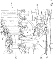
- the centrifugal wheel of the radial compressor has a relatively large exit diameter. This results in a reduced passage for the air supplied to the distributor of the first stage of the LP turbine. Moreover, as we see on the figure 2 , sampling in the middle of the HP compressor is often performed by means of centripetal sampling tubes which induce a significant loss of charge for the ventilation air.
- the object of the invention is to remedy the above problems by providing a means of correctly ventilating the LP turbine discs, more particularly in compact engines having a centrifugal compressor, and which takes into account the inherent space constraints. to this type of engine.
- the document JP 2005042669 discloses a low pressure turbine cooling air sampling means arranged between the high and medium pressure turbine sectors but it does not provide for attachment to one of the high pressure or low pressure turbine discs.
- the wheel When the compression wheel is secured to the HP turbine disk, advantageously the wheel then constitutes a structural element of the turbine disk forming the bearing support.
- the compression wheel comprises a disk provided with radial vanes cooperating with a stator partition to compress the air.
- the partition comprises air guide vanes.
- stator partition delimits with the HP turbine disk a HP turbine downstream cavity, and the air coming from the bore of the HP turbine disk feeds part of the wheel and part of the cavity.
- the motor comprises a second ventilation circuit, said circuit ventilating the hoods of the separate bearing oil chambers, in particular said second circuit comprises a guide duct portion coaxial with the guide portion of the first circuit.
- the invention also relates to a motor whose air compressor wheel comprises a radial web with a first annular portion provided with fixing holes and a second portion provided with radial fins.
- the first portion is radially internal with respect to the second portion.
- the first portion is radially external with respect to the second portion.
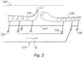
- a gas turbine engine said to be small, double body HP high pressure body comprises a turbine 110 connected to a compressor HP 115 by a shaft 117.
- the compressor 115 is of the centrifugal impeller type.
- the low pressure body comprises a low-pressure turbine 120 with several stages mounted on a shaft 127, coaxial with the shaft 117, being connected to a compressor 125 low pressure, axial type and itself having several stages.
- a combustion chamber 130 is disposed between the compressor and the HP body turbine.
- a distributor stage 140 separates the two turbines 110 and 120.
- a first ventilation air circuit E comprises an air intake upstream of the compressor HP and is directed axially between the two shafts 117 and 127 to through the bore of the turbine rotor 110 to ventilate the downstream turbine cavity.
- a second air circuit is guided between the outer casing 150 of the engine and the casing of the HP body via unrepresented tubes. It appears that such an arrangement is not satisfactory because the amount of air supplying the ventilation circuits is not sufficient.
- For the first circuit there is too little passage section between the shafts 117 and 127 for the ventilation air.
- For the second circuit there is little room for installing ventilation tubes on the housing.
- an air compressor wheel for ventilating the LP turbine there is arranged, downstream of the HP turbine disk, an air compressor wheel for ventilating the LP turbine.
- an air compressor wheel for ventilating the LP turbine On the figure 3 there is shown such a device.
- This figure only shows the disk 210D of the HP turbine 210 with a central bore 210A.
- the disk 210D is integral with the shaft 217. At its upstream end, the shaft 217 is integral with the compressor not visible in the figure.
- the disc supports HP 210T turbine blades receiving hot gases from the combustion chamber not visible in the figure.
- a distributor stator stage 220 is placed downstream of the HP turbine 210 immediately upstream of the blades of the LP 230 low-pressure turbine.
- This turbine is composed of several interconnected disks, of which one see only the first two 231 and 232.
- the turbine 230 is supported by a shaft 237.
- This shaft 237 is concentric with the shaft 217.
- a downstream shaft bearing 240 maintains the two concentric shafts and allows them to freely rotate one compared to each other.
- the upstream bearing is not visible in the figure, as the downstream bearing supporting the shaft 237 in the fixed structure.
- An annular space F is thus formed between the bore 210A of the turbine disc and the shaft 217.
- Another annular space G is also provided between the two shafts 217 and 237.
- the disk 210D comprises a flange 210B on which is bolted a compression wheel 300.
- the wheel comprises a generally disk-shaped portion perpendicular to the axis of the motor, with a first portion 301 axially pierced with a plurality of holes 303 for the passage of the bolts 303 'fixing the impeller to the flange 210B.
- Radially outside this portion the disk comprises an annular portion 305 provided with radial fins 307.
- This second portion cooperates with a fixed wall 222 to form a centrifugal air compressor means axial inlet and radial outlet.
- the wall 222 supports fins 222A for axial guidance at the inlet and fins 222S for radial guidance at the outlet of the compressor.
- An annular 222D deflector makes it possible to orient the flow of air leaving the compressor towards the base of the turbine disks 231 and 232.
- the wall 222 houses with the turbine disk 210D a space 211 forming said downstream cavity of an HP turbine.
- labyrinth seal 222L cooperates with a corresponding means 210L on the disc to contain the air in this cavity 211.
- the wheel comprises a cylindrical portion 309 forming a support of the outer ring 242 of the bearing 240.
- the rolling elements 244 are thus housed between the inner ring 246 integral with the shaft 237 and the outer ring 242 integral with the shaft 217 and form the inter-shaft bearing 240.
- the flange 210B is square with an axial cylindrical portion 210B1 and a perpendicular portion 210B2 comprising the bores, cooperating with the holes 303 for the passage of the bolts 303 '.
- the cylindrical portion 210B1 is pierced with radial holes 210B1r.
- An annular space is provided between the flange 210B, the wheel 300 and the wall 222.
- 222P radial holes are formed in the wall 222 between the fins 222A and 222L sealing.
- Holes 309P are formed in the cylindrical portion 309 of the impeller for communicating the gap G with the downstream portion of the low-pressure rotor 230.
- the device of the invention operates as follows.
- the two rotors HP and BP respectively are driven by the gases from the combustion chamber. They rotate each independently of each other.
- the ventilation air taken from the last stages of the upstream compressor in a first circuit is guided in the space F, and passes through the flange 210B through the holes 210B1r.
- One part is sucked by the wheel 300, the other part is guided through the holes 222P in the HP downstream cavity 211 that it ventilates.
- the compressed air in the compression channels of the impeller 300 is discharged towards the turbine disks 231 and 232, which it ventilates, and is discharged into the flue gas duct or through appropriate orifices through the support.
- the ventilation air taken at the level of the first stages of the HP compressor, which circulates in the annular space G, between the two shafts 217 and 237, is guided through the bores 309P downstream of the LP turbine, in particular to the enclosures of the bearing oil chambers.
- the HP turbine disc 210 ' is found with a downstream flange 210B' for attaching a labyrinth sealing element 210L '.
- the wheel 400 is here secured to the LP turbine disk 231 'by which it is driven.
- the wheel 400 as in the previous solution cooperates with the stator element 222 'to form air compression channels which is guided through the central bore of the disk 210D', the bores 210P 'made in the flange 210B and from the upstream compressor.
- the airflow is divided into a portion which purges the downstream cavity 211 'of the turbine disk 210' and a portion which is entrained in the compression channels of the wheel 400.
- the wheel 400 includes openings for ventilating the turbine disks. 231 'and 233'.
Landscapes
- Engineering & Computer Science (AREA)
- Chemical & Material Sciences (AREA)
- Combustion & Propulsion (AREA)
- Mechanical Engineering (AREA)
- General Engineering & Computer Science (AREA)
- Structures Of Non-Positive Displacement Pumps (AREA)
- Turbine Rotor Nozzle Sealing (AREA)
Description
- La présente invention concerne le domaine des moteurs à turbine à gaz et vise la circulation de l'air destiné à la ventilation et au refroidissement d'éléments situés en aval de la chambre de combustion, notamment les disques de turbine.
- Dans un moteur à turbine à gaz, il est nécessaire de faire circuler de l'air le long d'éléments soumis aux contraintes thermiques des gaz chauds en aval de la chambre de combustion pour en contrôler la température. Dans un moteur à double corps, on distingue le circuit d'air destiné à la ventilation de la section haute pression de celui destiné à ventiler la section basse pression située en aval, car les matériaux et les contraintes thermiques sont différents.
- La présente invention concerne ce deuxième circuit d'air.
- Dans un moteur à double corps actuel de type civil, tel que le moteur CFM, comprenant un corps haute pression HP avec un étage de turbine HP 1 et un corps basse pression BP avec une turbine BP 30 à trois étages 31, 32 et 33, les différents circuits assurant la ventilation en aval de la turbine haute pression sont représentés sur la
figure 1 ; on y distingue : - Un flux d'air A, prélevé au milieu du compresseur HP, acheminé au travers des pales du distributeur 20 du premier étage BP et assurant en A' la purge de la cavité aval 11 de la turbine HP 10.
- Une fraction A" de ce même flux assurant la ventilation des alésages des deux premiers disques des étages 31 et 32 de la turbine basse pression 30.
- Un flux d'air B prélevé en amont du compresseur HP, acheminé à travers l'alésage 13 de la turbine HP 10 et assurant la ventilation de l'alésage du troisième étage 33 de la turbine BP 30.
- Un flux d'air C prélevé au niveau du compresseur BP, acheminé à travers l'alésage 13 de la turbine HP 10, et assurant la pressurisation des capotages 36 des enceintes abritant les roulements.
- Les compresseurs pour ce type de moteur sont axiaux et présentent des espaces suffisants pour le guidage des différents flux d'air de ventilation depuis la zone de prélèvement jusqu'à leur application.
- Certains moteurs moins puissants et plus compacts ont un corps HP avec compresseur radial, plus court, et leur taux de compression est plus faible. Cette disposition présente des problèmes lorsqu'il s'agit d'assurer la fonction de ventilation rapportée ci-dessus.
- La pression ne suffit pas toujours à ventiler convenablement l'alésage des disques de turbine BP, et cette situation n'est pas favorisée par la faible section de passage entre l'alésage de la turbine HP et l'arbre BP.
- La roue centrifuge du compresseur radial a un diamètre de sortie relativement important. Il s'ensuit un passage réduit pour l'air acheminé vers le distributeur du premier étage de la turbine BP. Par ailleurs, comme on le voit sur la
figure 2 , le prélèvement au milieu du compresseur HP est souvent réalisé au moyen de tubes de prélèvement centripètes qui induisent une perte charge importante pour l'air de ventilation. - L'invention a pour objectif de remédier aux problèmes ci-dessus, en fournissant un moyen qui permet de ventiler correctement les disques de turbine BP, plus particulièrement dans les moteurs compacts présentant un compresseur centrifuge, et qui tient compte des contraintes d'encombrement propres à ce type de moteur.
- L'invention parvient à réaliser cet objectif avec un moteur présentant les caractéristiques énoncées dans la revendication 1.
- Grâce à l'invention, on utilise efficacement les circuits d'air à travers l'alésage de turbine, et il est aussi possible maintenant de simplifier la structure du distributeur de premier étage de la turbine basse pression car il n'est plus nécessaire d'en acheminer de l'air à travers les pales. Le document
JP 2005042669 - Lorsque le rouet de compression est solidaire du disque de turbine HP, avantageusement le rouet constitue alors un élément structurel du disque de turbine en formant le support de palier.
- Conformément à une autre caractéristique, le rouet de compression comprend un disque pourvu d'ailettes radiales coopérant avec une cloison de stator pour comprimer l'air. Avantageusement, la cloison comporte des ailettes de guidage d'air.
- Conformément à une autre caractéristique, la cloison de stator délimite avec le disque de turbine HP une cavité aval de turbine HP, et l'air provenant de l'alésage du disque de turbine HP alimente en partie le rouet et en partie la cavité.
- Conformément à une autre caractéristique le moteur comprend un deuxième circuit de ventilation, ledit circuit ventilant les capots des enceintes à huile de palier distinct, notamment ledit deuxième circuit comprend une partie formant conduit de guidage coaxial à la partie de guidage du premier circuit.
- L'invention porte également sur un moteur dont le rouet de compression d'air comprend un voile radial avec une première portion annulaire pourvue de perçages de fixation et une deuxième portion pourvue d'ailettes radiales. Selon un premier mode de réalisation, la première portion est radialement intérieure par rapport à la deuxième portion. Selon un deuxième mode de réalisation la première portion est radialement extérieure par rapport à la deuxième portion.
- La description qui suit porte sur deux modes de réalisation non limitatifs de l'invention, en référence aux dessins annexés sur lesquels,
- La
figure 1 montre en demi coupe axiale la partie d'un moteur à turbine à gaz à double corps de l'état de la technique, comprenant une turbine HP et une turbine BP, - La
figure 2 montre en demi coupe axiale un moteur avec un compresseur radial, de l'état de la technique, - La
figure 3 montre en demi coupe axiale un disque de turbine équipé d'un rouet conformément à l'invention, - La
figure 4 montre vu en perspective un rouet seul conforme à l'invention, - La
figure 5 montre un deuxième mode de réalisation - En se reportant à la
figure 2 , on voit un moteur à turbine à gaz, dit de petite taille, à double corps le corps haute pression HP comprend une turbine 110 reliée à un compresseur HP 115 par un arbre 117. Le compresseur 115 est du type à rouet centrifuge. Le corps basse pression comprend une turbine basse pression 120 à plusieurs étages montée sur un arbre 127, coaxial avec l'arbre 117, en étant relié à un compresseur 125 basse pression, de type axial et comportant lui-même plusieurs étages. Une chambre de combustion 130 est disposée entre le compresseur et la turbine du corps HP. Un étage distributeur 140 sépare les deux turbines 110 et 120. - Comme on le voit, sur cette figure sans la mise en oeuvre de l'invention, un premier circuit d'air de ventilation E comprend une prise d'air en amont du compresseur HP et est dirigé axialement entre les deux arbres 117 et 127 à travers l'alésage du rotor de turbine 110 pour ventiler la cavité aval de turbine. Un deuxième circuit d'air est guidé entre l'enveloppe extérieure 150 du moteur et le carter du corps HP via des tubes non représentés. Il apparaît qu'un tel agencement n'est pas satisfaisant car la quantité d'air alimentant les circuits de ventilation n'est pas suffisante.
Pour le premier circuit, il y a trop peu de section de passage entre les arbres 117 et 127 pour l'air de ventilation.
Pour le second circuit, il y a peu de place pour installer des tubes de ventilation sur le carter. - Conformément à l'invention, on a aménagé, en aval du disque de turbine HP, un rouet de compression de l'air destiné à la ventilation de la turbine BP. Sur la
figure 3 on a représenté un tel dispositif. - On ne voit sur cette figure que le disque 210D de la turbine HP 210 avec un alésage central 210A. Le disque 210D est solidaire de l'arbre 217. A son extrémité amont, l'arbre 217 est solidaire du compresseur non visible sur la figure. Le disque supporte des ailettes de turbine HP 210T recevant les gaz chauds de la chambre de combustion non visible sur la figure.
- Un étage statorique de distributeur 220 est placé en aval de la turbine HP 210 immédiatement en amont des ailettes de la turbine basse pression BP 230. Cette turbine est composée de plusieurs disques liés entre eux, dont on ne voit que les deux premiers 231 et 232. La turbine 230 est supportée par un arbre 237. Cet arbre 237 est concentrique à l'arbre 217. Un palier interarbre 240 aval maintient les deux arbres concentriques et leur permet de tourner librement l'un par rapport à l'autre. Le palier amont n'est pas visible sur la figure, tout comme le palier aval supportant l'arbre 237 dans la structure fixe. Un espace annulaire F est ainsi ménagé entre l'alésage 210A du disque de turbine et l'arbre 217. Un autre espace annulaire G est ménagé aussi entre les deux arbres 217 et 237.
- Le disque 210D comporte une bride 210B sur laquelle est boulonné un rouet de compression 300. Le rouet comporte une partie globalement en forme de disque perpendiculaire à l'axe du moteur, avec une première portion 301 percée axialement d'une pluralité de trous 303 pour le passage des boulons 303' de fixation du rouet à la bride 210B. Radialement à l'extérieur de cette portion le disque comporte une portion annulaire 305 pourvue d'ailettes radiales 307. Cette deuxième portion coopère avec une paroi fixe 222 pour former un moyen compresseur d'air centrifuge à entrée axiale et sortie radiale. La paroi 222 supporte des ailettes 222A de guidage axial en entrée et des ailettes 222S de guidage radial en sortie du compresseur. Un déflecteur 222D annulaire permet d'orienter le flux d'air sortant du compresseur vers la base des disques de turbine 231 et 232. La paroi 222 ménage avec le disque de turbine 210D un espace 211 formant ladite cavité aval de turbine HP un moyen d'étanchéité à labyrinthe 222L coopère avec un moyen correspondant 210L sur le disque pour contenir l'air dans cette cavité 211. On note que le rouet comprend une portion cylindrique 309 formant support de la bague extérieure 242 du palier 240. Les éléments de roulement 244 sont ainsi logés entre la bague intérieure 246 solidaire de l'arbre 237 et la bague extérieure 242 solidaire de l'arbre 217 et forment le palier interarbre 240.
- La bride 210B est en équerre avec une partie cylindrique axiale 210B1 et une partie perpendiculaire 210B2 comprenant les perçages, coopérant avec les perçages 303 pour le passage des boulons 303'. La partie cylindrique 210B1 est percée de trous radiaux 210B1r. Un espace annulaire est ménagé entre la bride 210B, le rouet 300 et la paroi 222. Des perçages radiaux 222P sont pratiqués dans la paroi 222 entre les ailettes 222A et l'étanchéité 222L.
- Des perçages 309P sont pratiqués dans la portion cylindrique 309 du rouet pour mettre en communication l'espace G avec la partie aval du rotor basse pression 230.
- Le dispositif de l'invention fonctionne de la façon suivante.
Lorsque le moteur est en fonctionnement, les deux rotors HP et BP respectivement sont entraînés par les gaz issus de la chambre de combustion. Ils tournent chacun indépendamment l'un de l'autre. L'air de ventilation prélevé au niveau des derniers étages du compresseur amont selon un premier circuit est guidé dans l'espace F, et traverse la bride 210B par les perçages 210B1r. Une partie est aspirée par le rouet 300, l'autre partie est guidée à travers les perçages 222P dans la cavité 211 aval de turbine HP qu'elle ventile. L'air comprimé dans les canaux de compression du rouet 300 est évacué en direction des disques de turbine 231 et 232 dont elle assure la ventilation, et est évacuée dans la veine de gaz de combustion ou bien par des orifices appropriés à travers le support de turbine BP 230. - L'air de ventilation, prélevé au niveau des premiers étages du compresseur HP, qui circule dans l'espace annulaire G, entre les deux arbres 217 et 237, est guidé à travers les perçages 309P vers l'aval de la turbine BP, notamment vers les capotages des enceintes d'huile de palier.
- Conformément à un autre mode de réalisation, représenté sur la
figure 5 , on retrouve le disque de turbine HP 210' avec une bride 210B' aval, de fixation d'un élément d'étanchéité à labyrinthe 210L'. Le rouet 400 est ici solidaire du disque de turbine BP 231' par lequel il est entraîné. Le rouet 400 comme dans la solution précédente coopère avec l'élément de stator 222' pour former des canaux de compression de l'air qui est guidé à travers l'alésage central du disque 210D', les perçages 210P' pratiqués dans la bride 210B' et provenant du compresseur amont. Le flux d'air se divise en une partie qui purge la cavité aval 211' du disque de turbine 210' et une partie qui est entraînée dans les canaux de compression du rouet 400. Le rouet 400 comprend des ouvertures pour ventiler les disques de turbine 231' et 233'.
Claims (13)
- Moteur à turbine à gaz comprenant deux rotors de turbine indépendants mécaniquement l'un par rapport à l'autre, chacun avec au moins un disque de turbine, respectivement disque de turbine HP (210D, 210D') et disque de turbine BP (231, 232 ; 231'), et un dispositif de ventilation d'éléments de turbine avec un premier circuit (F) de ventilation de la turbine BP (230 ; 230'), caractérisé par le fait qu'il comprend un rouet de compression d'air (300 ; 400) disposé en aval du disque de turbine HP pour assister la circulation de l'air dans le dit premier circuit (F) le rouet de compression étant solidaire soit du disque de turbine HP (210D) soit du disque de turbine BP (210D').
- Moteur selon la revendication 1 dont le rouet de compression est disposé entre lesdits deux disques de turbine HP et BP (210, 231 ; 210',231')
- Moteur selon l'une des revendications 1 et 2, dont le rouet (300 ; 400) de compression communique en entrée d'air avec l'alésage (210A ; 210A') du disque de turbine HP (210D ; 210D').
- Moteur selon la revendication précédente, dont l'alésage (210A ; 210A') est alimenté en air provenant du compresseur HP.
- Moteur selon l'une des revendications précédentes, dont le rouet (300 ; 400) de compression comprend un disque (303 ; 303') pourvu d'ailettes radiales (307 ; 307') coopérant avec une cloison (22, 22') de stator pour comprimer l'air.
- Moteur selon la revendication 5, dont la cloison comporte des ailettes de guidage d'air (222A, 222S ; 222A', 222S').
- Moteur, selon la revendication 5 ou 6, dont la cloison (222 ; 222') de stator délimite avec le disque de turbine HP une cavité (211 ; 211') aval de turbine HP.
- Moteur , selon la revendication 3 ou 4 combinée avec la revendication 6, dont l'air provenant de l'alésage alimente en partie le rouet et en partie la cavité.
- Moteur, selon l'une des revendications 1 à 8 comprenant un deuxième circuit (G) de ventilation, des capots des enceintes à huile de palier distinct.
- Moteur, selon la revendication 9 dont ledit deuxième circuit (G), comprend une partie de guidage coaxial à la partie de guidage du premier circuit (F).
- Moteur selon l'une des revendications précédentes dont le rouet de compression d'air comprend un voile radial avec une première portion annulaire pourvue de perçages de fixation et une deuxième portion pourvue d'ailettes radiales.
- Moteur, selon la revendication 11, dont la première portion du rouet est radialement intérieure par rapport à la deuxième portion.
- Moteur, selon la revendication 11, dont la première portion du rouet est radialement extérieure par rapport à la deuxième portion.
Applications Claiming Priority (1)
| Application Number | Priority Date | Filing Date | Title |
|---|---|---|---|
| FR0553216A FR2892454B1 (fr) | 2005-10-21 | 2005-10-21 | Dispositif de ventilation de disques de turbine dans un moteur a turbine a gaz |
Publications (2)
| Publication Number | Publication Date |
|---|---|
| EP1785588A1 EP1785588A1 (fr) | 2007-05-16 |
| EP1785588B1 true EP1785588B1 (fr) | 2016-04-13 |
Family
ID=36659953
Family Applications (1)
| Application Number | Title | Priority Date | Filing Date |
|---|---|---|---|
| EP06122697.3A Active EP1785588B1 (fr) | 2005-10-21 | 2006-10-20 | Dispositif de ventilation de disque de turbine dans un moteur à turbine à gaz |
Country Status (6)
| Country | Link |
|---|---|
| US (1) | US7766607B2 (fr) |
| EP (1) | EP1785588B1 (fr) |
| JP (1) | JP4834511B2 (fr) |
| CA (1) | CA2564491C (fr) |
| FR (1) | FR2892454B1 (fr) |
| RU (1) | RU2417322C2 (fr) |
Families Citing this family (21)
| Publication number | Priority date | Publication date | Assignee | Title |
|---|---|---|---|---|
| DE102007023380A1 (de) * | 2007-05-18 | 2008-11-20 | Mtu Aero Engines Gmbh | Gasturbine |
| FR2918414B1 (fr) * | 2007-07-06 | 2013-04-12 | Snecma | Dispositif d'alimentation en air de ventilation des aubes de turbine basse pression d'un moteur a turbine a gaz ; segment pour l'arret axial et la ventilation des aubes de turbine basse pression |
| JP4929217B2 (ja) * | 2008-03-28 | 2012-05-09 | 三菱重工業株式会社 | ガスタービンおよびガスタービンの中間軸ならびにガスタービン圧縮機の冷却方法 |
| FR2960260B1 (fr) * | 2010-05-21 | 2014-05-09 | Snecma | Turbomachine comprenant un circuit de ventilation de turbine basse pression ameliore |
| FR2968062B1 (fr) * | 2010-11-26 | 2012-11-16 | Snecma | Dispositif d'evacuation d'huile et turbomachine comprenant un tel dispositif |
| FR2983908B1 (fr) * | 2011-12-08 | 2015-02-20 | Snecma | Systeme pour assurer l’etancheite entre une enceinte d’huile et un volume exterieur attenant et turbomachine equipee d’un tel systeme d’etancheite. |
| DE102012208263A1 (de) * | 2012-05-16 | 2013-11-21 | Rolls-Royce Deutschland Ltd & Co Kg | Verdichtervorrichtung für eine Turbomaschine |
| FR2995021B1 (fr) * | 2012-09-04 | 2017-08-25 | Snecma | Dispositif d'alimentation en air pour turbines de moteurs d'aeronefs |
| KR102194926B1 (ko) * | 2013-03-21 | 2020-12-24 | 엘지전자 주식회사 | 무선 통신 시스템에서 채널상태정보 전송 방법 및 장치 |
| US9951621B2 (en) * | 2013-06-05 | 2018-04-24 | Siemens Aktiengesellschaft | Rotor disc with fluid removal channels to enhance life of spindle bolt |
| RU2534684C1 (ru) * | 2013-11-25 | 2014-12-10 | Российская Федерация, от имени которой выступает Министерство промышленности и торговли Российской Федерации (Минпромторг России) | Турбина двухконтурного газотурбинного двигателя |
| JP6167037B2 (ja) * | 2013-12-24 | 2017-07-19 | 三鷹光器株式会社 | 断熱軸受構造 |
| FR3023588B1 (fr) * | 2014-07-08 | 2016-07-15 | Turbomeca | Ensemble pour turbine destine a proteger un disque de turbine contre des gradients thermiques |
| FR3030614B1 (fr) * | 2014-12-17 | 2019-09-20 | Safran Aircraft Engines | Ensemble de turbine haute pression de turbomachine |
| US10267328B2 (en) | 2015-07-21 | 2019-04-23 | Rolls-Royce Corporation | Rotor structure for rotating machinery and method of assembly thereof |
| ES2698504T3 (es) | 2015-07-28 | 2019-02-05 | MTU Aero Engines AG | Turbina de gas |
| KR101744411B1 (ko) | 2015-10-15 | 2017-06-20 | 두산중공업 주식회사 | 가스터빈의 냉각장치 |
| CN107448240A (zh) * | 2016-05-31 | 2017-12-08 | 中国航发商用航空发动机有限责任公司 | 核心机和涡轮发动机 |
| EP3450722B1 (fr) * | 2017-08-31 | 2024-02-14 | General Electric Company | Système de distribution d'air pour moteur à turbine à gaz |
| FR3087839B1 (fr) * | 2018-10-30 | 2020-10-23 | Safran Aircraft Engines | Turbine |
| DE102021004405A1 (de) | 2021-08-30 | 2023-03-02 | Erich Würzinger | Verfahren zur effektiven Mischungs-Methodologie, Gemischbildung, fortschrittlicher Kraftstoffaufbereitung in einer emissionsarmen Brennkammer und zur Erzeugung von variabler Geometrie in Brennkammer und in der Hochdruckturbinenkapazität durch die Anwendung von komprimierter Verdichterzapfluft zur Anwendung in Fluggasturbinen und stationären Gasturbinen |
Family Cites Families (13)
| Publication number | Priority date | Publication date | Assignee | Title |
|---|---|---|---|---|
| SU119404A1 (ru) * | 1947-12-29 | 1958-11-30 | В.С. 1 Богословский | Турбина внутреннего сгорани |
| US4309147A (en) * | 1979-05-21 | 1982-01-05 | General Electric Company | Foreign particle separator |
| FR2732405B1 (fr) * | 1982-03-23 | 1997-05-30 | Snecma | Dispositif pour refroidir le rotor d'une turbine a gaz |
| US5134844A (en) * | 1990-07-30 | 1992-08-04 | General Electric Company | Aft entry cooling system and method for an aircraft engine |
| US5226785A (en) * | 1991-10-30 | 1993-07-13 | General Electric Company | Impeller system for a gas turbine engine |
| FR2712029B1 (fr) * | 1993-11-03 | 1995-12-08 | Snecma | Turbomachine pourvue d'un moyen de réchauffage des disques de turbines aux montées en régime. |
| US6217280B1 (en) * | 1995-10-07 | 2001-04-17 | Siemens Westinghouse Power Corporation | Turbine inter-disk cavity cooling air compressor |
| RU2133358C1 (ru) * | 1997-09-02 | 1999-07-20 | Акционерное общество открытого типа Авиамоторный научно-технический комплекс "Союз" | Авиационная силовая установка с дополнительным газотурбинным двигателем для воздушной пусковой системы и системы вентиляции и кондиционирования |
| US5984636A (en) * | 1997-12-17 | 1999-11-16 | Pratt & Whitney Canada Inc. | Cooling arrangement for turbine rotor |
| JP2001050003A (ja) * | 1999-08-03 | 2001-02-23 | Ishikawajima Harima Heavy Ind Co Ltd | ガスタービンエンジン |
| DE10009655C1 (de) * | 2000-02-29 | 2001-05-23 | Mtu Aero Engines Gmbh | Kühlluftsystem |
| JP2005042669A (ja) * | 2003-07-25 | 2005-02-17 | Hitachi Ltd | 2軸式ガスタービン |
| US6910852B2 (en) * | 2003-09-05 | 2005-06-28 | General Electric Company | Methods and apparatus for cooling gas turbine engine rotor assemblies |
-
2005
- 2005-10-21 FR FR0553216A patent/FR2892454B1/fr not_active Expired - Lifetime
-
2006
- 2006-10-19 CA CA2564491A patent/CA2564491C/fr active Active
- 2006-10-20 JP JP2006286118A patent/JP4834511B2/ja active Active
- 2006-10-20 EP EP06122697.3A patent/EP1785588B1/fr active Active
- 2006-10-20 US US11/551,560 patent/US7766607B2/en active Active
- 2006-10-20 RU RU2006137218/06A patent/RU2417322C2/ru active
Also Published As
| Publication number | Publication date |
|---|---|
| JP4834511B2 (ja) | 2011-12-14 |
| FR2892454B1 (fr) | 2008-01-25 |
| CA2564491A1 (fr) | 2007-04-21 |
| FR2892454A1 (fr) | 2007-04-27 |
| EP1785588A1 (fr) | 2007-05-16 |
| RU2006137218A (ru) | 2008-04-27 |
| US20070137221A1 (en) | 2007-06-21 |
| JP2007113586A (ja) | 2007-05-10 |
| RU2417322C2 (ru) | 2011-04-27 |
| US7766607B2 (en) | 2010-08-03 |
| CA2564491C (fr) | 2014-01-14 |
Similar Documents
| Publication | Publication Date | Title |
|---|---|---|
| EP1785588B1 (fr) | Dispositif de ventilation de disque de turbine dans un moteur à turbine à gaz | |
| CA2758175C (fr) | Moteur a turbine a gaz a double corps pourvu d ' un palier inter-arbres | |
| EP2440746B1 (fr) | Turbomachine comprenant des moyens ameliores de reglage du debit d'un flux d'air de refroidissement preleve en sortie de compresseur haute pression | |
| EP1503061B1 (fr) | Procédé de refroidissement, par air refroidi en partie dans un échangeur externe, des parties chaudes d'un turboréacteur, et turboréacteur ainsi refroidi. | |
| EP1445421B1 (fr) | Dispositif de ventilation d'un rotor de turbine à haute pression d'une turbomachine | |
| EP2337929B1 (fr) | Ventilation d'une turbine haute-pression dans une turbomachine | |
| EP1367221B1 (fr) | Système à double injecteurs fond de chambre pour le refroidissement du flasque amont d'une turbine à haute pression | |
| EP1552111A1 (fr) | Circuits de ventilation de la turbine d une turbomachine | |
| WO2021191528A1 (fr) | Turbomachine à double flux comprenant un dispositif de régulation du débit de fluide de refroidissement | |
| FR2464363A1 (fr) | Rotor de turbine pour turbomachines avec systeme de transfert de l'agent de refroidissement | |
| EP1504178B1 (fr) | Turboreacteur avec un carenage stator dans une cavite interne | |
| EP4127405B1 (fr) | Turbomachine avec dispositif de refroidissement et de pressurisation d'une turbine | |
| FR3164252A1 (fr) | Système de trains épicycloïdaux pour turbomachine et turbomachine comprenant un tel système | |
| FR3162832A1 (fr) | Dispositif de tourbillonnement radial pour chambre de combustion de turbomachine. | |
| FR3166165A1 (fr) | Module pour une turbomachine d’aeronef | |
| WO2025068641A1 (fr) | Dispositif pour le centrage et le guidage en rotation d'un arbre de turbomachine à lubrification optimisée d'éléments de roulement par du lubrifiant évacué depuis un sfd | |
| FR3166163A1 (fr) | Module pour une turbomachine d’aeronef | |
| FR3117529A1 (fr) | Turbomachine avec canalisation d’air secondaire comportant un systeme de deshuilage |
Legal Events
| Date | Code | Title | Description |
|---|---|---|---|
| PUAI | Public reference made under article 153(3) epc to a published international application that has entered the european phase |
Free format text: ORIGINAL CODE: 0009012 |
|
| 17P | Request for examination filed |
Effective date: 20061020 |
|
| AK | Designated contracting states |
Kind code of ref document: A1 Designated state(s): AT BE BG CH CY CZ DE DK EE ES FI FR GB GR HU IE IS IT LI LT LU LV MC NL PL PT RO SE SI SK TR |
|
| AX | Request for extension of the european patent |
Extension state: AL BA HR MK YU |
|
| AKX | Designation fees paid |
Designated state(s): DE FR GB |
|
| 17Q | First examination report despatched |
Effective date: 20080117 |
|
| 17Q | First examination report despatched |
Effective date: 20120221 |
|
| GRAP | Despatch of communication of intention to grant a patent |
Free format text: ORIGINAL CODE: EPIDOSNIGR1 |
|
| RAP1 | Party data changed (applicant data changed or rights of an application transferred) |
Owner name: SNECMA |
|
| INTG | Intention to grant announced |
Effective date: 20151221 |
|
| GRAS | Grant fee paid |
Free format text: ORIGINAL CODE: EPIDOSNIGR3 |
|
| GRAA | (expected) grant |
Free format text: ORIGINAL CODE: 0009210 |
|
| AK | Designated contracting states |
Kind code of ref document: B1 Designated state(s): DE FR GB |
|
| REG | Reference to a national code |
Ref country code: GB Ref legal event code: FG4D Free format text: NOT ENGLISH |
|
| REG | Reference to a national code |
Ref country code: DE Ref legal event code: R096 Ref document number: 602006048618 Country of ref document: DE |
|
| RAP2 | Party data changed (patent owner data changed or rights of a patent transferred) |
Owner name: SAFRAN AIRCRAFT ENGINES |
|
| REG | Reference to a national code |
Ref country code: FR Ref legal event code: PLFP Year of fee payment: 11 |
|
| REG | Reference to a national code |
Ref country code: DE Ref legal event code: R097 Ref document number: 602006048618 Country of ref document: DE |
|
| PLBE | No opposition filed within time limit |
Free format text: ORIGINAL CODE: 0009261 |
|
| STAA | Information on the status of an ep patent application or granted ep patent |
Free format text: STATUS: NO OPPOSITION FILED WITHIN TIME LIMIT |
|
| 26N | No opposition filed |
Effective date: 20170116 |
|
| REG | Reference to a national code |
Ref country code: FR Ref legal event code: PLFP Year of fee payment: 12 |
|
| REG | Reference to a national code |
Ref country code: FR Ref legal event code: PLFP Year of fee payment: 13 |
|
| PGFP | Annual fee paid to national office [announced via postgrant information from national office to epo] |
Ref country code: DE Payment date: 20251020 Year of fee payment: 20 |
|
| PGFP | Annual fee paid to national office [announced via postgrant information from national office to epo] |
Ref country code: GB Payment date: 20251029 Year of fee payment: 20 |
|
| PGFP | Annual fee paid to national office [announced via postgrant information from national office to epo] |
Ref country code: FR Payment date: 20251023 Year of fee payment: 20 |