EP1785590A1 - Pièce et procédé de soudage pour la fabrication d'une pièce - Google Patents
Pièce et procédé de soudage pour la fabrication d'une pièce Download PDFInfo
- Publication number
- EP1785590A1 EP1785590A1 EP05405627A EP05405627A EP1785590A1 EP 1785590 A1 EP1785590 A1 EP 1785590A1 EP 05405627 A EP05405627 A EP 05405627A EP 05405627 A EP05405627 A EP 05405627A EP 1785590 A1 EP1785590 A1 EP 1785590A1
- Authority
- EP
- European Patent Office
- Prior art keywords
- cover part
- welding
- guide vane
- base body
- welded
- Prior art date
- Legal status (The legal status is an assumption and is not a legal conclusion. Google has not performed a legal analysis and makes no representation as to the accuracy of the status listed.)
- Withdrawn
Links
- 238000003466 welding Methods 0.000 title claims abstract description 67
- 238000000034 method Methods 0.000 title claims abstract description 36
- 238000004519 manufacturing process Methods 0.000 title abstract description 7
- 239000000463 material Substances 0.000 claims description 10
- 238000003754 machining Methods 0.000 claims description 7
- PXHVJJICTQNCMI-UHFFFAOYSA-N Nickel Chemical compound [Ni] PXHVJJICTQNCMI-UHFFFAOYSA-N 0.000 claims description 6
- 229910052751 metal Inorganic materials 0.000 claims description 6
- 239000002184 metal Substances 0.000 claims description 6
- 229910001092 metal group alloy Inorganic materials 0.000 claims description 6
- 229910000601 superalloy Inorganic materials 0.000 claims description 6
- 229910000831 Steel Inorganic materials 0.000 claims description 4
- 229910045601 alloy Inorganic materials 0.000 claims description 4
- 239000000956 alloy Substances 0.000 claims description 4
- 229910001026 inconel Inorganic materials 0.000 claims description 4
- 229910000816 inconels 718 Inorganic materials 0.000 claims description 4
- 239000010959 steel Substances 0.000 claims description 4
- UQZIWOQVLUASCR-UHFFFAOYSA-N alumane;titanium Chemical compound [AlH3].[Ti] UQZIWOQVLUASCR-UHFFFAOYSA-N 0.000 claims description 3
- 230000003628 erosive effect Effects 0.000 claims description 3
- 238000005242 forging Methods 0.000 claims description 3
- 229910052759 nickel Inorganic materials 0.000 claims description 3
- RTAQQCXQSZGOHL-UHFFFAOYSA-N Titanium Chemical compound [Ti] RTAQQCXQSZGOHL-UHFFFAOYSA-N 0.000 claims 1
- 229910052782 aluminium Inorganic materials 0.000 claims 1
- XAGFODPZIPBFFR-UHFFFAOYSA-N aluminium Chemical group [Al] XAGFODPZIPBFFR-UHFFFAOYSA-N 0.000 claims 1
- 239000010936 titanium Substances 0.000 claims 1
- 229910052719 titanium Inorganic materials 0.000 claims 1
- 230000000694 effects Effects 0.000 description 12
- 238000003801 milling Methods 0.000 description 7
- 239000011343 solid material Substances 0.000 description 7
- 230000008030 elimination Effects 0.000 description 3
- 238000003379 elimination reaction Methods 0.000 description 3
- 230000006378 damage Effects 0.000 description 2
- 230000001419 dependent effect Effects 0.000 description 2
- 230000004927 fusion Effects 0.000 description 2
- 150000002739 metals Chemical class 0.000 description 2
- 229910001220 stainless steel Inorganic materials 0.000 description 2
- 230000007704 transition Effects 0.000 description 2
- 230000005540 biological transmission Effects 0.000 description 1
- 238000005336 cracking Methods 0.000 description 1
- 210000003298 dental enamel Anatomy 0.000 description 1
- 238000010894 electron beam technology Methods 0.000 description 1
- 238000005552 hardfacing Methods 0.000 description 1
- 238000002844 melting Methods 0.000 description 1
- 230000008018 melting Effects 0.000 description 1
- 238000001338 self-assembly Methods 0.000 description 1
- 230000035939 shock Effects 0.000 description 1
- 239000010935 stainless steel Substances 0.000 description 1
- 230000003746 surface roughness Effects 0.000 description 1
Images

Classifications
-
- B—PERFORMING OPERATIONS; TRANSPORTING
- B23—MACHINE TOOLS; METAL-WORKING NOT OTHERWISE PROVIDED FOR
- B23K—SOLDERING OR UNSOLDERING; WELDING; CLADDING OR PLATING BY SOLDERING OR WELDING; CUTTING BY APPLYING HEAT LOCALLY, e.g. FLAME CUTTING; WORKING BY LASER BEAM
- B23K33/00—Specially-profiled edge portions of workpieces for making soldering or welding connections; Filling the seams formed thereby
- B23K33/004—Filling of continuous seams
-
- B—PERFORMING OPERATIONS; TRANSPORTING
- B23—MACHINE TOOLS; METAL-WORKING NOT OTHERWISE PROVIDED FOR
- B23K—SOLDERING OR UNSOLDERING; WELDING; CLADDING OR PLATING BY SOLDERING OR WELDING; CUTTING BY APPLYING HEAT LOCALLY, e.g. FLAME CUTTING; WORKING BY LASER BEAM
- B23K26/00—Working by laser beam, e.g. welding, cutting or boring
- B23K26/20—Bonding
- B23K26/21—Bonding by welding
- B23K26/24—Seam welding
-
- B—PERFORMING OPERATIONS; TRANSPORTING
- B23—MACHINE TOOLS; METAL-WORKING NOT OTHERWISE PROVIDED FOR
- B23K—SOLDERING OR UNSOLDERING; WELDING; CLADDING OR PLATING BY SOLDERING OR WELDING; CUTTING BY APPLYING HEAT LOCALLY, e.g. FLAME CUTTING; WORKING BY LASER BEAM
- B23K26/00—Working by laser beam, e.g. welding, cutting or boring
- B23K26/20—Bonding
- B23K26/21—Bonding by welding
- B23K26/24—Seam welding
- B23K26/28—Seam welding of curved planar seams
-
- F—MECHANICAL ENGINEERING; LIGHTING; HEATING; WEAPONS; BLASTING
- F01—MACHINES OR ENGINES IN GENERAL; ENGINE PLANTS IN GENERAL; STEAM ENGINES
- F01D—NON-POSITIVE DISPLACEMENT MACHINES OR ENGINES, e.g. STEAM TURBINES
- F01D5/00—Blades; Blade-carrying members; Heating, heat-insulating, cooling or antivibration means on the blades or the members
- F01D5/02—Blade-carrying members, e.g. rotors
- F01D5/04—Blade-carrying members, e.g. rotors for radial-flow machines or engines
- F01D5/043—Blade-carrying members, e.g. rotors for radial-flow machines or engines of the axial inlet- radial outlet, or vice versa, type
- F01D5/048—Form or construction
-
- F—MECHANICAL ENGINEERING; LIGHTING; HEATING; WEAPONS; BLASTING
- F01—MACHINES OR ENGINES IN GENERAL; ENGINE PLANTS IN GENERAL; STEAM ENGINES
- F01D—NON-POSITIVE DISPLACEMENT MACHINES OR ENGINES, e.g. STEAM TURBINES
- F01D5/00—Blades; Blade-carrying members; Heating, heat-insulating, cooling or antivibration means on the blades or the members
- F01D5/34—Rotor-blade aggregates of unitary construction, e.g. formed of sheet laminae
-
- F—MECHANICAL ENGINEERING; LIGHTING; HEATING; WEAPONS; BLASTING
- F04—POSITIVE - DISPLACEMENT MACHINES FOR LIQUIDS; PUMPS FOR LIQUIDS OR ELASTIC FLUIDS
- F04D—NON-POSITIVE-DISPLACEMENT PUMPS
- F04D29/00—Details, component parts, or accessories
- F04D29/18—Rotors
- F04D29/22—Rotors specially for centrifugal pumps
- F04D29/2205—Conventional flow pattern
- F04D29/2222—Construction and assembly
- F04D29/2227—Construction and assembly for special materials
-
- F—MECHANICAL ENGINEERING; LIGHTING; HEATING; WEAPONS; BLASTING
- F04—POSITIVE - DISPLACEMENT MACHINES FOR LIQUIDS; PUMPS FOR LIQUIDS OR ELASTIC FLUIDS
- F04D—NON-POSITIVE-DISPLACEMENT PUMPS
- F04D29/00—Details, component parts, or accessories
- F04D29/26—Rotors specially for elastic fluids
- F04D29/28—Rotors specially for elastic fluids for centrifugal or helico-centrifugal pumps for radial-flow or helico-centrifugal pumps
- F04D29/284—Rotors specially for elastic fluids for centrifugal or helico-centrifugal pumps for radial-flow or helico-centrifugal pumps for compressors
-
- B—PERFORMING OPERATIONS; TRANSPORTING
- B23—MACHINE TOOLS; METAL-WORKING NOT OTHERWISE PROVIDED FOR
- B23K—SOLDERING OR UNSOLDERING; WELDING; CLADDING OR PLATING BY SOLDERING OR WELDING; CUTTING BY APPLYING HEAT LOCALLY, e.g. FLAME CUTTING; WORKING BY LASER BEAM
- B23K2101/00—Articles made by soldering, welding or cutting
- B23K2101/001—Turbines
-
- F—MECHANICAL ENGINEERING; LIGHTING; HEATING; WEAPONS; BLASTING
- F05—INDEXING SCHEMES RELATING TO ENGINES OR PUMPS IN VARIOUS SUBCLASSES OF CLASSES F01-F04
- F05D—INDEXING SCHEME FOR ASPECTS RELATING TO NON-POSITIVE-DISPLACEMENT MACHINES OR ENGINES, GAS-TURBINES OR JET-PROPULSION PLANTS
- F05D2220/00—Application
- F05D2220/40—Application in turbochargers
-
- F—MECHANICAL ENGINEERING; LIGHTING; HEATING; WEAPONS; BLASTING
- F05—INDEXING SCHEMES RELATING TO ENGINES OR PUMPS IN VARIOUS SUBCLASSES OF CLASSES F01-F04
- F05D—INDEXING SCHEME FOR ASPECTS RELATING TO NON-POSITIVE-DISPLACEMENT MACHINES OR ENGINES, GAS-TURBINES OR JET-PROPULSION PLANTS
- F05D2230/00—Manufacture
- F05D2230/20—Manufacture essentially without removing material
- F05D2230/23—Manufacture essentially without removing material by permanently joining parts together
- F05D2230/232—Manufacture essentially without removing material by permanently joining parts together by welding
- F05D2230/234—Laser welding
-
- F—MECHANICAL ENGINEERING; LIGHTING; HEATING; WEAPONS; BLASTING
- F05—INDEXING SCHEMES RELATING TO ENGINES OR PUMPS IN VARIOUS SUBCLASSES OF CLASSES F01-F04
- F05D—INDEXING SCHEME FOR ASPECTS RELATING TO NON-POSITIVE-DISPLACEMENT MACHINES OR ENGINES, GAS-TURBINES OR JET-PROPULSION PLANTS
- F05D2300/00—Materials; Properties thereof
- F05D2300/10—Metals, alloys or intermetallic compounds
- F05D2300/17—Alloys
-
- F—MECHANICAL ENGINEERING; LIGHTING; HEATING; WEAPONS; BLASTING
- F05—INDEXING SCHEMES RELATING TO ENGINES OR PUMPS IN VARIOUS SUBCLASSES OF CLASSES F01-F04
- F05D—INDEXING SCHEME FOR ASPECTS RELATING TO NON-POSITIVE-DISPLACEMENT MACHINES OR ENGINES, GAS-TURBINES OR JET-PROPULSION PLANTS
- F05D2300/00—Materials; Properties thereof
- F05D2300/10—Metals, alloys or intermetallic compounds
- F05D2300/17—Alloys
- F05D2300/175—Superalloys
Definitions
- the invention relates to a workpiece, in particular impeller, impeller, or stator for a turbine, a pump or a compressor, and a welding method for producing a workpiece according to the preamble of the independent claim of the respective category.
- the centrifugal compressor like the centrifugal pump, essentially consists of a rotating impeller, also called impeller, which is mounted on an axle and may be open as well as provided with a cover, the impeller in particular being arranged in an enclosing stationary impeller may or may be enclosed by a spiral collecting space.
- the stator has the shape of a diffuser, in which part of the kinetic energy generated in the rotor is converted into pressure energy.
- the stator consists in this embodiment substantially of a top plate and a bottom plate, also referred to as a lid or floor, between which vanes may be located.
- the axial compressor comprising a rotor and a stator, consists in a known manner of a designed as an impeller rotor with drive shaft and vanes, wherein the wheels can be designed with or without outer ring, ie with or without cover part.
- the stator is formed as a comprehensive housing in which the fixed guide wheels are housed, and not in any case, such as certain fans, a stator must be provided.
- the impellers are highly loaded in the operating condition, as they are sometimes driven at enormous rotational speeds of, for example, up to 15,000 rpm with a diameter of the impeller of e.g. 400 mm considerable centrifugal forces are exposed. In this case, circumferential speeds at the outer diameter of up to 400 m / s and more are typically achievable.
- the wheels made of solid material, depending on the application, for example, from high-strength stainless steels, superalloys or other suitable metals or metal alloys to manufacture and work out the vanes by machining, eg by milling, from this material.
- the impellers additionally have to be equipped with a cover part in the form of a cover, it is often no longer possible, purely geometrically, to cut the impeller in one piece from solid material, but either becomes a one-piece one Main body, which sits on the drive axis of the compressor, worked out with guide vanes, so that a cover part must be subsequently placed on the vanes and connected reliably with them.
- a cover part with guide vanes is worked in one piece of solid material, and the main body, which is coupled to the drive axle, with the cover part with vanes later assembled and connected to a complete impeller ,
- the problematic part is thus the connection of the guide vanes with an associated cover part or with a base body.
- the DE 102 61 262 A1 specifies a method with which by means of laser welding or electron welding guide vanes with shields are connected by means of butt or weld through seams.
- the object of the invention is therefore to provide a workpiece, in particular an impeller, an impeller or a stator for a turbine, a pump or a compressor, in which a cover part and / or a base body is reliably welded to associated vanes, so that a safe operation even under extreme operating conditions, such as at very high rotational speed guaranteed.
- Another object of the invention is to provide a welding method for producing such workpieces.
- the invention thus relates to a workpiece, in particular impeller, impeller, or stator for a turbine, for a pump or for a compressor, comprising a main body with a guide vane, wherein the guide vane on the main body and / or on a cover part is not kerbok welded.
- the elimination of internal notch effects is preferably carried out by blanket fusion of the vane with the cover part and / or the main body by a plurality of overlapping welding paths.
- the elimination of external notch effects in the angle between a foot and / or a tip of the vane and the cover part and / or the base body is e.g. achieved by pre-milling a transition radius on the guide vane, which is also welded to the cover part and / or the base body.
- the elimination of notch effects by surface roughness is ensured by the planar laser welding process as such, since it leaves a smooth enamel surface on the side facing away from the beam feed when melting the outlet of the preformed radius of the guide vane.
- the milling of grooves in the cover part and / or in the base body can be provided at a depth leaving a weldable residual wall thickness at the groove bottom.
- the welding can also be done by combining different welding processes.
- the planar welding process is an electron beam welding, while the outer areas are welded with a laser beam, or vice versa.
- guide vane can be provided in specific embodiments either on the cover part or on the base body or at the same time on the base body and on the cover part.
- the invention relates in particular to fast rotating wheels and the welding method according to the invention is particularly advantageously used for welding rapidly rotating workpieces, such as fast rotating wheels.
- the invention also relates to fixed guide wheels which are, for example, particularly resistant to strong thermal loads or to other mechanical loads, e.g. Must be Strömungsbefastungen that in the operating state, e.g. A turbine, a pump or a compressor can occur, which therefore does not concern only the stresses caused by centrifugal forces.
- impeller made of solid material according to the invention, depending on the application e.g. made of high strength stainless steel, superalloy or other suitable metal or metal alloy, and the vanes are machined, e.g. by milling, worked out of this material.
- the blade channels on the base body and / or on the cover part can also be replaced by other suitable methods, e.g. by eroding, forging. Welding, etc. can be made.
- the impellers as in the case of an impeller, must be additionally equipped with a cover part in the form of a lid, it is no longer possible purely geometrical reasons to mill the impeller in one piece of solid material, but either becomes a one-piece body , which is mountable on the drive axis of the compressor, machined with guide vanes, so that a cover part is subsequently placed on the guide vanes and welded to them reliably according to an inventive welding method.
- the cover part is worked with guide vanes in one piece of solid material, and the main body which is coupled to the drive axle, with the cover part with guide vanes is subsequently welded to a complete impeller according to an inventive welding process.
- the invention also concerns impellers and guide wheels without cover part and the inventive method is also advantageously used for the production of such workpieces.
- the invention relates to a workpiece, wherein the guide vane on the base body and / or on the cover part with an energy beam, in particular with a laser beam, in particular by laser deep welding, well under the English term "key-hole welding" the expert well is known, is welded.
- the guide vane is preferably completely over a whole width of a contact surface between the base body and / or the cover part, i. welded flat. This avoids the dreaded notch effects that occur with the welded workpieces known in the prior art.
- the guide vane in the region of the contact surface is particularly advantageously designed so that it extends in the direction of the contact surface extending, in particular in the form of a milled circular arc.
- the base body and / or the cover part has a thickness which is so large that it can not be welded by the welding beam, in particular by the laser beam, may be in the base body and / or in the cover part on a side facing away from the contact surface the guide vane to be provided a welding trough, so that the thickness to be welded through is reduced.
- the welding trough is filled with a filling material, ie the welding trough, after welding, can be refilled again with a filling material, for example by means of application welding.
- the vane can be removed by means of a machining process, e.g. be worked out by milling, from the body and / or from the cover part.
- nickel-base alloys in particular Inconel, in particular Inconel 718, a superalloy. Steel, titanium aluminum or other suitable metals or metal alloys in question.
- the invention further relates to a welding method for producing a workpiece, in particular impeller, impeller, or stator for a turbine, a pump or a compressor, comprising a base body with a guide vane, wherein the guide vane is welded kerbok on the base body and / or on a cover part.
- the guide vane is preferably welded to the base body and / or the cover part with an energy beam, in particular with a laser beam, in particular by laser deep welding, the vane particularly advantageous over a full width of a contact surface between the body and / or the cover part completely, i. is welded flat.
- the guide vane in the area of the contact surface can extend widening in the direction of the contact surface and the guide vane is also welded without a notch in the region of a boundary line of the contact surface.
- a welding trough can be provided in the base body and / or in the cover part on a side facing away from the contact surface, wherein the welding trough filled with a filling material, in particular by means of hardfacing, after the actual welding process again can be.
- the guide vane is machined by means of a machining process, in particular by milling from the base body and / or from the cover part.
- the base body and / or the vane and / or the cover part is advantageously made of a nickel-based alloy, in particular Inconel, in particular Inconel 718, a superalloy of steel, titanium aluminum or another suitable metal or a metal alloy.
- Fig. 1 is a schematic representation of an impeller example of a centrifugal compressor, shown in section and in the corresponding plan view, the basic geometry is well known per se.
- the impeller according to the invention which will be referred to in its entirety by the reference numeral 1, comprises in a manner known per se a base body 2 which is rotatably arranged about an axis A on a drive axle, for example in a compressor. From the main body 2, a plurality of vanes 3 is machined by means of a machining process, for example by turning or milling.
- the impeller In a substantially radial outward direction, the impeller is covered by a cover part 4 which extends radially outwards along an axial direction and which is welded to the guide vanes 3 by means of a welding method according to the invention.
- the weld 41, at the cover part 4 with the Guide vanes 3 is welded securely and not kerbok, can be clearly seen in Fig. 1.
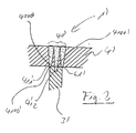
- FIG. 2 partially and in section shows an impeller 1 'with cover part 4' which corresponds geometrically essentially to the impeller 1 according to the invention according to FIG Impeller 1 ', however, was not welded by means of a erfindurgsdorfen welding process, but was welded by a known method, as for example in the DE 102 61 262 A1 was proposed.
- the cover part 4 'of the impeller 1 of FIG. 2 was welded to the guide blade 3' by means of a deep welding process, in the present case by means of laser deep welding.
- a deep welding process in the present case by means of laser deep welding.
- the thickness of the cover member 4 ' is dimensioned so that the energy beam, in the present case, the laser beam, the cover part 4' preferably into the anseschlweissenden body 3 ', so here can penetrate into the guide blade 3' during the welding process.
- the guide vane 3 ' has been welded to the cover part 4' by way of three more or less separately separated deep-welding points 411 ', 412'.
- the notches are formed not only by the fact that two or more, more or less separate deep-welding points 411 ', 412' were introduced.
- the geometric configuration of the guide vanes in the region of the weld itself already leads to a very damaging notch effect.
- the guide vanes known from the prior art more or less sharp-edged, in the extreme case, as shown in the example of FIG. 2 even at an angle of about 90 ° to the cover part 4 'abut, arise at the boundary line 61', which defines the radial boundary of the vane 3 'in the region in which the vane 3' adjoins the cover part 4 ', when welding automatically notches, which affect the strength and quality of the welded joint massively negative.
- both the welding over more or less separate deep-welding points 411 ', 412', as well as the geometry of the guide vane in the region of the welded connection can lead to undesirable notch effects that negatively affect the strength of the welded connection influence.
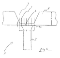
- an impeller according to FIG. 1 is shown schematically, which has been welded with a welding method according to the invention.
- this is an impeller 1
- the a cover part 4 has such a thickness D that the energy beam 5, in the present example, the laser beam 5, is not able to penetrate the entire thickness D of the cover part 4.
- a cover part 4 of such a large thickness D may be necessary, for example, when very large forces act on the cover part 4 in the operating state, so that a particularly high stability of the cover part 4 has to be ensured.
- the guide blade 3 can be welded to the cover part 4 by means of laser deep welding, which is known per se, a weld recess 7 is provided in the cover part 4 on a side of the guide blade 3 facing away from the contact surface 6.
- the laser beam 5 only has to penetrate the reduced thickness d on the cover part 4 during laser deep welding.
- the impeller according to the invention is uniformly and completely welded over an entire width B of the contact surface 6 between the base body 2 and the cover part 4. That is, it is not, as known in the art, more or less separate deep-welding points 411 '. 412 ', but it is welded over the entire width B of the contact surface 6 between the main body 2 and the cover part 4 evenly and completely flat, so that the dreaded notches, which arise inter alia by localized deep welding, by the surface welding according to the present invention be avoided.
- the guide blade 3 extends in the region of the contact surface 6 in the direction of the contact surface 6, preferably in the form of a circular arc, for example, ie under a predetermined constant or non-constant radius, and thus the guide blade 3 is not in one more or less sharp-edged shock to the cover part 4 abuts.
- the extension is not necessarily in the form of a radius, but e.g. can also be designed in the form of an oblique platform.
- the function of the expanding guide vane is also the enlargement of the connection surface, so that larger forces can be transmitted.
Landscapes
- Engineering & Computer Science (AREA)
- Mechanical Engineering (AREA)
- General Engineering & Computer Science (AREA)
- Physics & Mathematics (AREA)
- Optics & Photonics (AREA)
- Plasma & Fusion (AREA)
- Ceramic Engineering (AREA)
- Structures Of Non-Positive Displacement Pumps (AREA)
Priority Applications (4)
| Application Number | Priority Date | Filing Date | Title |
|---|---|---|---|
| EP05405627A EP1785590A1 (fr) | 2005-11-10 | 2005-11-10 | Pièce et procédé de soudage pour la fabrication d'une pièce |
| EP06793527.0A EP1948907B1 (fr) | 2005-11-10 | 2006-09-14 | Pièce et procédé de soudage pour la fabrication d'une pièce |
| PCT/EP2006/066376 WO2007054391A1 (fr) | 2005-11-10 | 2006-09-14 | Piece a usiner, ainsi que procede de soudage pour la fabrication d'une piece a usiner |
| US12/084,722 US8162614B2 (en) | 2005-11-10 | 2006-09-14 | Workpiece, and also a welding method for the manufacture of a workpiece |
Applications Claiming Priority (1)
| Application Number | Priority Date | Filing Date | Title |
|---|---|---|---|
| EP05405627A EP1785590A1 (fr) | 2005-11-10 | 2005-11-10 | Pièce et procédé de soudage pour la fabrication d'une pièce |
Publications (1)
| Publication Number | Publication Date |
|---|---|
| EP1785590A1 true EP1785590A1 (fr) | 2007-05-16 |
Family
ID=36129916
Family Applications (2)
| Application Number | Title | Priority Date | Filing Date |
|---|---|---|---|
| EP05405627A Withdrawn EP1785590A1 (fr) | 2005-11-10 | 2005-11-10 | Pièce et procédé de soudage pour la fabrication d'une pièce |
| EP06793527.0A Not-in-force EP1948907B1 (fr) | 2005-11-10 | 2006-09-14 | Pièce et procédé de soudage pour la fabrication d'une pièce |
Family Applications After (1)
| Application Number | Title | Priority Date | Filing Date |
|---|---|---|---|
| EP06793527.0A Not-in-force EP1948907B1 (fr) | 2005-11-10 | 2006-09-14 | Pièce et procédé de soudage pour la fabrication d'une pièce |
Country Status (3)
| Country | Link |
|---|---|
| US (1) | US8162614B2 (fr) |
| EP (2) | EP1785590A1 (fr) |
| WO (1) | WO2007054391A1 (fr) |
Cited By (5)
| Publication number | Priority date | Publication date | Assignee | Title |
|---|---|---|---|---|
| EP2047938A1 (fr) * | 2007-10-10 | 2009-04-15 | Hitachi Plant Technologies, Ltd. | Procédé et appareil de soudage de turbine |
| DE102014215089A1 (de) | 2014-07-31 | 2016-02-04 | Ksb Aktiengesellschaft | Strömungsführendes Bauteil |
| DE102016207495A1 (de) * | 2016-05-02 | 2017-09-21 | Voith Patent Gmbh | Verfahren zur Herstellung eines Laufrades vom Typ Francis |
| DE102016222312A1 (de) * | 2016-11-14 | 2018-05-17 | Man Diesel & Turbo Se | Strömungsmaschinenrotor und Verfahren zum Herstellen desselben |
| CN113927113A (zh) * | 2021-09-23 | 2022-01-14 | 贵州永红航空机械有限责任公司 | 用于闭式叶轮钎焊的钎料及钎焊装配方法 |
Families Citing this family (5)
| Publication number | Priority date | Publication date | Assignee | Title |
|---|---|---|---|---|
| WO2006059971A2 (fr) * | 2004-12-01 | 2006-06-08 | United Technologies Corporation | Logement de moteur a turbine integrant un ventilateur, un combustor, et une turbine |
| EP2012957B1 (fr) * | 2006-04-12 | 2010-01-06 | Sulzer Markets and Technology AG | Procede d'enlevement de copeaux |
| US9174426B1 (en) * | 2012-03-06 | 2015-11-03 | Florida Turbine Technologies, Inc. | Method of manufacturing a shrouded centrifugal impeller for high speed use |
| US10436211B2 (en) | 2016-08-15 | 2019-10-08 | Borgwarner Inc. | Compressor wheel, method of making the same, and turbocharger including the same |
| IT202200016164A1 (it) * | 2022-07-29 | 2022-10-29 | Nuovo Pignone Tecnologie Srl | Metodo per la produzione di una girante chiusa |
Citations (5)
| Publication number | Priority date | Publication date | Assignee | Title |
|---|---|---|---|---|
| DE2130127A1 (de) * | 1971-06-18 | 1972-12-28 | Kraftwerk Union Ag | Verfahren zum Verschweissen des Schaufelblattes einer Stroemungs- maschinen-,insbesondere Turbomaschinenschaufel mit einem Schaufelbfussstueck |
| DE2830037A1 (de) * | 1978-01-12 | 1979-07-19 | Nuovo Pignone Spa | Verfahren zum elektrischen schweissen |
| EP1239116A2 (fr) * | 2001-03-07 | 2002-09-11 | General Electric Company | Rotor intégral nervuré |
| DE10213914A1 (de) * | 2002-03-28 | 2003-10-09 | Gebhardt Ventilatoren | Verfahren zur Herstellung eines Ventilatorlaufrads |
| DE10343760A1 (de) * | 2003-09-22 | 2005-04-14 | Mtu Aero Engines Gmbh | Verfahren zur Herstellung oder Reparatur eines beschaufelten Rotors für eine Strömungsmaschine sowie dafür geeignete Schaufeln bzw. Ersatzschaufelabschnitte |
Family Cites Families (1)
| Publication number | Priority date | Publication date | Assignee | Title |
|---|---|---|---|---|
| US20050139581A1 (en) * | 2003-12-24 | 2005-06-30 | Yiping Hu | High-strength superalloy joining method for repairing turbine blades |
-
2005
- 2005-11-10 EP EP05405627A patent/EP1785590A1/fr not_active Withdrawn
-
2006
- 2006-09-14 EP EP06793527.0A patent/EP1948907B1/fr not_active Not-in-force
- 2006-09-14 WO PCT/EP2006/066376 patent/WO2007054391A1/fr not_active Ceased
- 2006-09-14 US US12/084,722 patent/US8162614B2/en not_active Expired - Fee Related
Patent Citations (5)
| Publication number | Priority date | Publication date | Assignee | Title |
|---|---|---|---|---|
| DE2130127A1 (de) * | 1971-06-18 | 1972-12-28 | Kraftwerk Union Ag | Verfahren zum Verschweissen des Schaufelblattes einer Stroemungs- maschinen-,insbesondere Turbomaschinenschaufel mit einem Schaufelbfussstueck |
| DE2830037A1 (de) * | 1978-01-12 | 1979-07-19 | Nuovo Pignone Spa | Verfahren zum elektrischen schweissen |
| EP1239116A2 (fr) * | 2001-03-07 | 2002-09-11 | General Electric Company | Rotor intégral nervuré |
| DE10213914A1 (de) * | 2002-03-28 | 2003-10-09 | Gebhardt Ventilatoren | Verfahren zur Herstellung eines Ventilatorlaufrads |
| DE10343760A1 (de) * | 2003-09-22 | 2005-04-14 | Mtu Aero Engines Gmbh | Verfahren zur Herstellung oder Reparatur eines beschaufelten Rotors für eine Strömungsmaschine sowie dafür geeignete Schaufeln bzw. Ersatzschaufelabschnitte |
Cited By (9)
| Publication number | Priority date | Publication date | Assignee | Title |
|---|---|---|---|---|
| EP2047938A1 (fr) * | 2007-10-10 | 2009-04-15 | Hitachi Plant Technologies, Ltd. | Procédé et appareil de soudage de turbine |
| US8426766B2 (en) | 2007-10-10 | 2013-04-23 | Hitachi Plant Technologies, Ltd. | Welding method and welding apparatus for an impeller |
| DE102014215089A1 (de) | 2014-07-31 | 2016-02-04 | Ksb Aktiengesellschaft | Strömungsführendes Bauteil |
| US10393133B2 (en) | 2014-07-31 | 2019-08-27 | Ksb Aktiengesellschaft | Flow-conducting component |
| DE102016207495A1 (de) * | 2016-05-02 | 2017-09-21 | Voith Patent Gmbh | Verfahren zur Herstellung eines Laufrades vom Typ Francis |
| DE102016222312A1 (de) * | 2016-11-14 | 2018-05-17 | Man Diesel & Turbo Se | Strömungsmaschinenrotor und Verfahren zum Herstellen desselben |
| US11078800B2 (en) | 2016-11-14 | 2021-08-03 | Man Energy Solutions Se | Turbomachine rotor and method for producing same |
| DE102016222312B4 (de) * | 2016-11-14 | 2025-12-31 | Everllence Se | Strömungsmaschinenrotor und Verfahren zum Herstellen desselben |
| CN113927113A (zh) * | 2021-09-23 | 2022-01-14 | 贵州永红航空机械有限责任公司 | 用于闭式叶轮钎焊的钎料及钎焊装配方法 |
Also Published As
| Publication number | Publication date |
|---|---|
| US20090252606A1 (en) | 2009-10-08 |
| EP1948907A1 (fr) | 2008-07-30 |
| WO2007054391A1 (fr) | 2007-05-18 |
| EP1948907B1 (fr) | 2016-11-09 |
| US8162614B2 (en) | 2012-04-24 |
Similar Documents
| Publication | Publication Date | Title |
|---|---|---|
| EP2012957B1 (fr) | Procede d'enlevement de copeaux | |
| EP3299117B1 (fr) | Procédé de fabrication ou de réparation d'un composant d'une machine tournante et composant produit ou réparé selon un tel procédé | |
| EP3251787A1 (fr) | Procédé de fabrication d'un composant de machine rotative et composant fabriqué selon un tel procédé | |
| WO2010046353A1 (fr) | Procédé de fabrication de roues fermées | |
| EP3421157A1 (fr) | Procédé de fabrication d'une roue d'une machine tournante et roue fabriquée selon un tel procédé | |
| EP2198128A1 (fr) | Procédé de production de blisk ou de bling, élément ainsi obtenu et aube de turbine | |
| EP1948907B1 (fr) | Pièce et procédé de soudage pour la fabrication d'une pièce | |
| EP2669042A1 (fr) | Procédé de fabrication d'une pièce usinée à l'aide d'un dispositif de découpe rapide | |
| DE102008049055B4 (de) | Verfahren zur Reparatur eines Gehäuseflanschs eines Flugzeugtriebwerks | |
| DE60317522T2 (de) | Maschinelle bearbeitung von turbinenrotoren unter verwendung von becherwerkzeugen | |
| EP1289702A1 (fr) | Procede pour le fraisage d'encoches en arete de poisson | |
| EP3081669B1 (fr) | Procede de fabrication de roues porteuses coiffees | |
| EP3299116B1 (fr) | Procédé de fabrication ou de réparation d'un composant d'une machine tournante et composant produit ou réparé selon un tel procédé | |
| DE102013012167B4 (de) | Vorrichtung zur spanenden Bearbeitung von Kanten | |
| DE10352542A1 (de) | Fräswerkzeug und Verfahren zum Fräsen von Vertiefungen | |
| EP3281728A1 (fr) | Procédé de fabrication d'un composant d'une machine rotative et composant fabriqué selon un tel procédé | |
| EP3708282B1 (fr) | Outil annulaire destiné à l'usinage d'une pièce à usiner | |
| EP1393836B1 (fr) | Méthode de fabrication d'ébauches pour éléments aubagés et matrice de forgeage | |
| EP1048389A2 (fr) | Protection pour la surface d'une pièce | |
| DE10343760B4 (de) | Verfahren zur Herstellung oder Reparatur eines beschaufelten Rotors für eine Strömungsmaschine sowie dafür geeignete Schaufeln bzw. Ersatzschaufelabschnitte | |
| WO2006087074A1 (fr) | Connexion d'un arbre a une roue de turbine d'un turbocompresseur de gaz d'echappement | |
| DE2719316A1 (de) | Verfahren und einrichtung zum herstellen von teilen einer stroemungsmaschine | |
| DE102006037906B4 (de) | Fräswerkzeug und Verfahren zu seiner Herstellung | |
| DE102022123029A1 (de) | Laufrad für eine Strömungsmaschine und Verfahren zur Herstellung eines Laufrades | |
| DE102014225330A1 (de) | Verfahren zur Herstellung einer Fan-Blisk einer Gasturbine |
Legal Events
| Date | Code | Title | Description |
|---|---|---|---|
| PUAI | Public reference made under article 153(3) epc to a published international application that has entered the european phase |
Free format text: ORIGINAL CODE: 0009012 |
|
| AK | Designated contracting states |
Kind code of ref document: A1 Designated state(s): AT BE BG CH CY CZ DE DK EE ES FI FR GB GR HU IE IS IT LI LT LU LV MC NL PL PT RO SE SI SK TR |
|
| AX | Request for extension of the european patent |
Extension state: AL BA HR MK YU |
|
| STAA | Information on the status of an ep patent application or granted ep patent |
Free format text: STATUS: THE APPLICATION HAS BEEN WITHDRAWN |
|
| 18W | Application withdrawn |
Effective date: 20070614 |