EP1785782A2 - Hologramme de sécurité et procédés associés d'utilisation et de fabrication de celui-ci - Google Patents
Hologramme de sécurité et procédés associés d'utilisation et de fabrication de celui-ci Download PDFInfo
- Publication number
- EP1785782A2 EP1785782A2 EP06023486A EP06023486A EP1785782A2 EP 1785782 A2 EP1785782 A2 EP 1785782A2 EP 06023486 A EP06023486 A EP 06023486A EP 06023486 A EP06023486 A EP 06023486A EP 1785782 A2 EP1785782 A2 EP 1785782A2
- Authority
- EP
- European Patent Office
- Prior art keywords
- image
- hologram
- holographic
- holographic image
- recording medium
- Prior art date
- Legal status (The legal status is an assumption and is not a legal conclusion. Google has not performed a legal analysis and makes no representation as to the accuracy of the status listed.)
- Withdrawn
Links
Images


Classifications
-
- G—PHYSICS
- G03—PHOTOGRAPHY; CINEMATOGRAPHY; ANALOGOUS TECHNIQUES USING WAVES OTHER THAN OPTICAL WAVES; ELECTROGRAPHY; HOLOGRAPHY
- G03H—HOLOGRAPHIC PROCESSES OR APPARATUS
- G03H1/00—Holographic processes or apparatus using light, infrared or ultraviolet waves for obtaining holograms or for obtaining an image from them; Details peculiar thereto
- G03H1/22—Processes or apparatus for obtaining an optical image from holograms
-
- G—PHYSICS
- G03—PHOTOGRAPHY; CINEMATOGRAPHY; ANALOGOUS TECHNIQUES USING WAVES OTHER THAN OPTICAL WAVES; ELECTROGRAPHY; HOLOGRAPHY
- G03H—HOLOGRAPHIC PROCESSES OR APPARATUS
- G03H1/00—Holographic processes or apparatus using light, infrared or ultraviolet waves for obtaining holograms or for obtaining an image from them; Details peculiar thereto
- G03H1/04—Processes or apparatus for producing holograms
-
- B—PERFORMING OPERATIONS; TRANSPORTING
- B44—DECORATIVE ARTS
- B44F—SPECIAL DESIGNS OR PICTURES
- B44F1/00—Designs or pictures characterised by special or unusual light effects
- B44F1/08—Designs or pictures characterised by special or unusual light effects characterised by colour effects
- B44F1/10—Changing, amusing, or secret pictures
-
- G—PHYSICS
- G03—PHOTOGRAPHY; CINEMATOGRAPHY; ANALOGOUS TECHNIQUES USING WAVES OTHER THAN OPTICAL WAVES; ELECTROGRAPHY; HOLOGRAPHY
- G03H—HOLOGRAPHIC PROCESSES OR APPARATUS
- G03H1/00—Holographic processes or apparatus using light, infrared or ultraviolet waves for obtaining holograms or for obtaining an image from them; Details peculiar thereto
- G03H1/0005—Adaptation of holography to specific applications
- G03H1/0011—Adaptation of holography to specific applications for security or authentication
-
- G—PHYSICS
- G03—PHOTOGRAPHY; CINEMATOGRAPHY; ANALOGOUS TECHNIQUES USING WAVES OTHER THAN OPTICAL WAVES; ELECTROGRAPHY; HOLOGRAPHY
- G03H—HOLOGRAPHIC PROCESSES OR APPARATUS
- G03H1/00—Holographic processes or apparatus using light, infrared or ultraviolet waves for obtaining holograms or for obtaining an image from them; Details peculiar thereto
- G03H1/04—Processes or apparatus for producing holograms
- G03H1/0402—Recording geometries or arrangements
- G03H1/041—Optical element in the object space affecting the object beam, not otherwise provided for
-
- G—PHYSICS
- G03—PHOTOGRAPHY; CINEMATOGRAPHY; ANALOGOUS TECHNIQUES USING WAVES OTHER THAN OPTICAL WAVES; ELECTROGRAPHY; HOLOGRAPHY
- G03H—HOLOGRAPHIC PROCESSES OR APPARATUS
- G03H1/00—Holographic processes or apparatus using light, infrared or ultraviolet waves for obtaining holograms or for obtaining an image from them; Details peculiar thereto
- G03H1/22—Processes or apparatus for obtaining an optical image from holograms
- G03H1/2249—Holobject properties
-
- G—PHYSICS
- G03—PHOTOGRAPHY; CINEMATOGRAPHY; ANALOGOUS TECHNIQUES USING WAVES OTHER THAN OPTICAL WAVES; ELECTROGRAPHY; HOLOGRAPHY
- G03H—HOLOGRAPHIC PROCESSES OR APPARATUS
- G03H1/00—Holographic processes or apparatus using light, infrared or ultraviolet waves for obtaining holograms or for obtaining an image from them; Details peculiar thereto
- G03H1/26—Processes or apparatus specially adapted to produce multiple sub- holograms or to obtain images from them, e.g. multicolour technique
- G03H1/2645—Multiplexing processes, e.g. aperture, shift, or wavefront multiplexing
-
- G—PHYSICS
- G03—PHOTOGRAPHY; CINEMATOGRAPHY; ANALOGOUS TECHNIQUES USING WAVES OTHER THAN OPTICAL WAVES; ELECTROGRAPHY; HOLOGRAPHY
- G03H—HOLOGRAPHIC PROCESSES OR APPARATUS
- G03H1/00—Holographic processes or apparatus using light, infrared or ultraviolet waves for obtaining holograms or for obtaining an image from them; Details peculiar thereto
- G03H1/26—Processes or apparatus specially adapted to produce multiple sub- holograms or to obtain images from them, e.g. multicolour technique
- G03H1/28—Processes or apparatus specially adapted to produce multiple sub- holograms or to obtain images from them, e.g. multicolour technique superimposed holograms only
-
- G—PHYSICS
- G07—CHECKING-DEVICES
- G07D—HANDLING OF COINS OR VALUABLE PAPERS, e.g. TESTING, SORTING BY DENOMINATIONS, COUNTING, DISPENSING, CHANGING OR DEPOSITING
- G07D7/00—Testing specially adapted to determine the identity or genuineness of valuable papers or for segregating those which are unacceptable, e.g. banknotes that are alien to a currency
- G07D7/003—Testing specially adapted to determine the identity or genuineness of valuable papers or for segregating those which are unacceptable, e.g. banknotes that are alien to a currency using security elements
- G07D7/0032—Testing specially adapted to determine the identity or genuineness of valuable papers or for segregating those which are unacceptable, e.g. banknotes that are alien to a currency using security elements using holograms
-
- G—PHYSICS
- G07—CHECKING-DEVICES
- G07D—HANDLING OF COINS OR VALUABLE PAPERS, e.g. TESTING, SORTING BY DENOMINATIONS, COUNTING, DISPENSING, CHANGING OR DEPOSITING
- G07D7/00—Testing specially adapted to determine the identity or genuineness of valuable papers or for segregating those which are unacceptable, e.g. banknotes that are alien to a currency
- G07D7/06—Testing specially adapted to determine the identity or genuineness of valuable papers or for segregating those which are unacceptable, e.g. banknotes that are alien to a currency using wave or particle radiation
- G07D7/12—Visible light, infrared or ultraviolet radiation
- G07D7/128—Viewing devices
-
- G—PHYSICS
- G03—PHOTOGRAPHY; CINEMATOGRAPHY; ANALOGOUS TECHNIQUES USING WAVES OTHER THAN OPTICAL WAVES; ELECTROGRAPHY; HOLOGRAPHY
- G03H—HOLOGRAPHIC PROCESSES OR APPARATUS
- G03H1/00—Holographic processes or apparatus using light, infrared or ultraviolet waves for obtaining holograms or for obtaining an image from them; Details peculiar thereto
- G03H1/04—Processes or apparatus for producing holograms
- G03H1/0402—Recording geometries or arrangements
- G03H1/0406—Image plane or focused image holograms, i.e. an image of the object or holobject is formed on, in or across the recording plane
-
- G—PHYSICS
- G03—PHOTOGRAPHY; CINEMATOGRAPHY; ANALOGOUS TECHNIQUES USING WAVES OTHER THAN OPTICAL WAVES; ELECTROGRAPHY; HOLOGRAPHY
- G03H—HOLOGRAPHIC PROCESSES OR APPARATUS
- G03H1/00—Holographic processes or apparatus using light, infrared or ultraviolet waves for obtaining holograms or for obtaining an image from them; Details peculiar thereto
- G03H1/04—Processes or apparatus for producing holograms
- G03H1/20—Copying holograms by holographic, i.e. optical means
- G03H1/202—Contact copy when the reconstruction beam for the master H1 also serves as reference beam for the copy H2
-
- G—PHYSICS
- G03—PHOTOGRAPHY; CINEMATOGRAPHY; ANALOGOUS TECHNIQUES USING WAVES OTHER THAN OPTICAL WAVES; ELECTROGRAPHY; HOLOGRAPHY
- G03H—HOLOGRAPHIC PROCESSES OR APPARATUS
- G03H1/00—Holographic processes or apparatus using light, infrared or ultraviolet waves for obtaining holograms or for obtaining an image from them; Details peculiar thereto
- G03H1/22—Processes or apparatus for obtaining an optical image from holograms
- G03H1/2286—Particular reconstruction light ; Beam properties
-
- G—PHYSICS
- G03—PHOTOGRAPHY; CINEMATOGRAPHY; ANALOGOUS TECHNIQUES USING WAVES OTHER THAN OPTICAL WAVES; ELECTROGRAPHY; HOLOGRAPHY
- G03H—HOLOGRAPHIC PROCESSES OR APPARATUS
- G03H1/00—Holographic processes or apparatus using light, infrared or ultraviolet waves for obtaining holograms or for obtaining an image from them; Details peculiar thereto
- G03H1/0005—Adaptation of holography to specific applications
- G03H1/0011—Adaptation of holography to specific applications for security or authentication
- G03H2001/0016—Covert holograms or holobjects requiring additional knowledge to be perceived, e.g. holobject reconstructed only under IR illumination
-
- G—PHYSICS
- G03—PHOTOGRAPHY; CINEMATOGRAPHY; ANALOGOUS TECHNIQUES USING WAVES OTHER THAN OPTICAL WAVES; ELECTROGRAPHY; HOLOGRAPHY
- G03H—HOLOGRAPHIC PROCESSES OR APPARATUS
- G03H1/00—Holographic processes or apparatus using light, infrared or ultraviolet waves for obtaining holograms or for obtaining an image from them; Details peculiar thereto
- G03H1/22—Processes or apparatus for obtaining an optical image from holograms
- G03H1/2249—Holobject properties
- G03H2001/2252—Location of the holobject
- G03H2001/2257—Straddling the hologram
-
- G—PHYSICS
- G03—PHOTOGRAPHY; CINEMATOGRAPHY; ANALOGOUS TECHNIQUES USING WAVES OTHER THAN OPTICAL WAVES; ELECTROGRAPHY; HOLOGRAPHY
- G03H—HOLOGRAPHIC PROCESSES OR APPARATUS
- G03H1/00—Holographic processes or apparatus using light, infrared or ultraviolet waves for obtaining holograms or for obtaining an image from them; Details peculiar thereto
- G03H1/22—Processes or apparatus for obtaining an optical image from holograms
- G03H1/2249—Holobject properties
- G03H2001/2281—Particular depth of field
-
- G—PHYSICS
- G03—PHOTOGRAPHY; CINEMATOGRAPHY; ANALOGOUS TECHNIQUES USING WAVES OTHER THAN OPTICAL WAVES; ELECTROGRAPHY; HOLOGRAPHY
- G03H—HOLOGRAPHIC PROCESSES OR APPARATUS
- G03H1/00—Holographic processes or apparatus using light, infrared or ultraviolet waves for obtaining holograms or for obtaining an image from them; Details peculiar thereto
- G03H1/26—Processes or apparatus specially adapted to produce multiple sub- holograms or to obtain images from them, e.g. multicolour technique
- G03H1/2645—Multiplexing processes, e.g. aperture, shift, or wavefront multiplexing
- G03H2001/2665—Coherence multiplexing wherein different holobjects are perceived under coherent or incoherent illumination
-
- G—PHYSICS
- G03—PHOTOGRAPHY; CINEMATOGRAPHY; ANALOGOUS TECHNIQUES USING WAVES OTHER THAN OPTICAL WAVES; ELECTROGRAPHY; HOLOGRAPHY
- G03H—HOLOGRAPHIC PROCESSES OR APPARATUS
- G03H2210/00—Object characteristics
- G03H2210/30—3D object
-
- G—PHYSICS
- G03—PHOTOGRAPHY; CINEMATOGRAPHY; ANALOGOUS TECHNIQUES USING WAVES OTHER THAN OPTICAL WAVES; ELECTROGRAPHY; HOLOGRAPHY
- G03H—HOLOGRAPHIC PROCESSES OR APPARATUS
- G03H2210/00—Object characteristics
- G03H2210/30—3D object
- G03H2210/33—3D/2D, i.e. the object is formed of stratified 2D planes, e.g. tomographic data
-
- G—PHYSICS
- G03—PHOTOGRAPHY; CINEMATOGRAPHY; ANALOGOUS TECHNIQUES USING WAVES OTHER THAN OPTICAL WAVES; ELECTROGRAPHY; HOLOGRAPHY
- G03H—HOLOGRAPHIC PROCESSES OR APPARATUS
- G03H2222/00—Light sources or light beam properties
- G03H2222/20—Coherence of the light source
- G03H2222/22—Spatial coherence
-
- G—PHYSICS
- G03—PHOTOGRAPHY; CINEMATOGRAPHY; ANALOGOUS TECHNIQUES USING WAVES OTHER THAN OPTICAL WAVES; ELECTROGRAPHY; HOLOGRAPHY
- G03H—HOLOGRAPHIC PROCESSES OR APPARATUS
- G03H2222/00—Light sources or light beam properties
- G03H2222/20—Coherence of the light source
- G03H2222/24—Low coherence light normally not allowing valuable record or reconstruction
Definitions
- This invention pertains to a hologram having a first holographic image located at or near a surface of a recording medium used to record the hologram and a second holographic image that is located in either a foreground position or a background position relative to the surface of the recording medium.
- This invention also pertains to an associated method of use of the hologram in security and/or authentication applications and to a method of making the hologram.
- Holography is a form of optical information storage.
- the general principles are described in a number of references, e.g., " Photography by Laser” by E. N. Leith and J. Upatnieks in SCIENTIFIC AMERICAN, 212, No. 6, 24-35 (June, 1965 ).
- the object to be photographed or imaged is illuminated with collimated light, e.g., from a laser, and a light sensitive recording medium, e.g., a photographic plate, is positioned so as to receive light reflected from the object.
- a light sensitive recording medium e.g., a photographic plate
- Each point on the object reflects light to the entire recording medium, and each point on the medium receives light from the entire object. This beam of reflected light is known as the object beam.
- a portion of the collimated light is beamed by a mirror directly to the medium, by passing the object.
- This beam is known as the reference beam.
- What is recorded on the recording medium is the interference pattern that results from the interaction of the reference beam and the object beam impinging on the medium.
- An image plane by definition is an area of focus and/or an area of attention of a 3-dimensional image.
- An image plane is also called a focal plane.
- Holograms that are formed by allowing the reference and object beams to enter the recording medium from the same side are known as transmission holograms and are also known as front beam holograms. Interaction of the object and reference beams in the recording medium forms fringes of material with varying refractive indices which are normal or near normal to the plane of the recording medium. When the hologram is played back by viewing with transmitted light, these fringes diffract the light to produce a viewable virtual image.
- Such transmission holograms may be produced by methods which are well known in the art, such as those disclosed in U.S. Patent No. 3,506,327 ; U.S. Patent No. 3,838,903 and U.S. Patent No. 3,894,787 .
- Holograms formed by allowing the reference and object beams to enter the recording medium from opposite sides, so that they are traveling in approximately opposite directions, are known as reflection holograms and are also known as back beam holograms.
- Interaction of the object and reference beams in the recording medium forms fringes of material with varying refractive indices which are, approximately, planes parallel to the plane of the recording medium.
- these fringes act as mirrors reflecting incident light back to the viewer.
- the hologram is viewed in reflection rather than in transmission. Since the wavelength sensitivity of this type of hologram is very high, white light may be used for reconstruction.
- Reflection holograms produced by an off-axis process are disclosed in U.S. Patent No. 3,532,406 .
- holograms as described above are being used as an enhanced security means attached to commercial products, such as digital optical disks, compact disks, batteries for electronic products, and any other product that may be susceptible to counterfeiting efforts.
- a simple hologram(s) for identification and authentication purposes on such products is known.
- a hologram is a surface-relief hologram formed by a stamping process. This process may be incorporated into the manufacturing process of the product.
- holograms volume-phase hologram
- the present invention provides a solution for this important need.
- the present invention is directed to a security hologram recorded in a recording medium having a surface and containing an integral image, the hologram comprising a first holographic image, which is located and plays back at or near the surface of the recording medium and which is characterized to possess a first image plane and to possess a first center wavelength, and a second holographic image, which is located and plays back at a position with respect to the surface of the recording medium that is selected from the group consisting of a foreground position and a background position and which is characterized to possess a second image plane and to possess a second center wavelength, wherein at least a portion of the first holographic image and at least a portion of the second holographic image together afford the integral image.
- the invention is further directed to a method for viewing a reconstructed image of a hologram recorded in a recording medium having a surface and containing an integral image, the hologram comprising a first holographic image, which is located and plays back at the surface of the recording medium and which is characterized to possess a first image plane and to possess a first center wavelength and a first spectral bandwidth, and a second holographic image, which is located and plays back at a position with respect to the surface of the recording medium that is selected from the group consisting of a foreground position and a background position and which is characterized to possess a second image plane and to possess a second center wavelength and a second spectral bandwidth; wherein at least a portion of the first holographic image and at least a portion of the second holographic image together afford the integral image; said method comprising:
- the invention is still further directed to a method for establishing the authenticity of an article containing a hologram recorded in a recording medium having a surface and containing an integral image, the hologram comprising a first holographic image, which is located and plays back at the surface of the recording medium and which is characterized to possess a first image plane and to possess a first center wavelength and a first spectral bandwidth, and a second holographic image, which is located and plays back at a position with respect to the surface of the recording medium that is selected from the group consisting of a foreground position and a background position and which is characterized to possess a second image plane and to possess a second center wavelength and a second spectral bandwidth; wherein at least a portion of the first holographic image and at least a portion of the second holographic image together afford the integral image; said method comprising the steps of:
- the invention is still further directed to a method for making a hologram, said hologram being recorded in a recording medium having a surface and containing an integral image, the hologram comprising a first holographic image, which is located and plays back at the surface of the recording medium and which is characterized to possess a first image plane and to possess a first center wavelength and a first spectral bandwidth, and a second holographic image, which is located and plays back at a position with respect to the surface of the recording medium that is selected from the group consisting of a foreground position and a background position and which is characterized to possess a second image plane and to possess a second center wavelength and a second spectral bandwidth; wherein at least a portion of the first holographic image and at least a portion of the second holographic image together afford the integral image; the method comprising the steps of:
- the present invention is a hologram recorded in a recording medium and containing an integral image.
- the hologram comprises a first holographic image, which possesses a first image plane, and a second holographic image, which possesses a second image plane.
- the first image plane can be located at or near a surface of the recording medium.
- the second image plane is located either in a background position or a foreground position.
- the first and second holographic images together afford the integral image.
- the integral image is formed of the first and second holographic images like fitting together pieces of a jigsaw puzzle. The pieces may be curved, rectangular or of any shape that accomplishes an integral image.
- the image is viewable in totality for imparting security and/or authenification information and checks, etc., only under appropriate illumination conditions (as indicated herein).
- at least a portion of the first holographic image and at least a portion of the second holographic image together afford the image.
- the invention is also directed to a method for viewing a reconstructed image of a hologram wherein the method comprises: providing the hologram comprising the first holographic image and the second holographic image, wherein the second holographic image appears unrecognizable to the human eye under diffuse lighting sources; and illuminating the hologram with at least a partially collimated light source having a spectral bandwidth that overlaps the spectral bandwidth of the first holographic image and the spectral bandwidth of the second holographic image, wherein the image is viewable and recognizable to a human eye and is seen by the human eye as the integral image.
- the invention is directed to a method for establishing the authenticity of an article bearing a hologram containing an integral image and recorded in a recording medium having a surface, the hologram comprising a first holographic image, which is located and plays back at or near the surface of the recording medium and which is characterized to possess a first image plane and to possess a first center wavelength and a first spectral bandwidth, and a second holographic image, which is located and plays back at a position with respect to the surface of the recording medium that is selected from a foreground position and a background position and which is characterized to possess a second image plane and to possess a second center wavelength and a second spectral bandwidth; wherein at least a portion of the first holographic image and at least a portion of the second holographic image together afford the integral image; said method comprises the steps of:
- the first and second wavelengths may independently be selected from, for example, the visible region of the electromagnetic spectrum, the infrared region of the electromagnetic spectrum, and the ultraviolet region of the electromagnetic spectrum.
- the invention is a method for making a hologram, said hologram being recorded in a recording medium having a surface and thereby containing an integral image, the hologram comprising a first holographic image, which is located and plays back at or near the surface of the recording medium and which is characterized to possess a first image plane and to possess a first center wavelength and a first spectral bandwidth, and a second holographic image, which is located and plays back at a position with respect to the surface of the recording medium that is selected from the group of consisting of a foreground position and a background position and which is characterized to possess a second image plane and to possess a second center wavelength and a second spectral bandwidth; wherein at least a portion of the first holographic image and at least a portion of the second holographic image together afford the integral image; the method comprises the steps of:
- One embodiment of the present invention utilizes holographic images manufactured by a volume reflection method used in the holographic industry for producing and reconstructing three-dimensional images from a hologram comprising forming a pattern of interference fringes on a photographic plate wherein the object-bearing beam and reference beam impinge on opposite sides of a photographic plate and reconstructing the image by illuminating the hologram with at least a partially collimated light source to view the reconstructed image.
- An at least partially collimated light source is a light source wherein at least some of the light is produced in a parallel beam of radiation.
- the at least partially collimated light source may be a non-coherent light source and has a spectral bandwidth that substantially overlaps the spectral bandwidth of the first holographic image and the spectral bandwidth of the second holographic image, wherein the reconstructed image is viewable and recognizable to a human eye as the integral image.
- Another embodiment utilizes holographic images manufactured by an embossed method. Embossing methods are well known in the art of holographics.
- the reconstructed image may be used as a security device for authenticity verification.
- the light source may be the light of a laser or other monochromatic collimated source.
- a reflection (back-beam) hologram behaves as a selective reflecting filter, reconstructing the image in a narrow band of wavelengths that appear as a single color.
- the particular spectral band that is visible in the reconstruction depends markedly on the geometry of construction.
- the reconstruction color tends to shift to a shorter wavelength because of distortion or shrinkage of the emulsion that changes the spacing of the interference fringe pattern.
- it is possible to control the amount of spectral shift by adjustment of the processing variables during development.
- multiple images and images using radiation of more than one wavelength can be stored in the hologram. It is possible to reconstruct multicolor images from reflection (back-beam) holograms viewed by reflection in white light, each color being selectively reflected from the hologram and combined in the image to yield a colored image that appears truly three-dimensional.
- the beam 11 from a source of collimated and coherent light 13 is divided by suitable means, such as a beam splitter 15, into a reference beam 17 and an incident beam 19.
- the incident beam 19 illuminates an object 21.
- the reflected light or object-bearing beam 23 from the object 21 passes to holographic recording medium (HRM, e.g., photographic or dichromated gelatin) plate 25.
- HRM holographic recording medium
- the reference beam 17 is directed onto the HRM plate 25 by suitable means such as a mirror 27, but strikes the plate 25 on the side opposite that is illuminated by the object-bearing beam 23.
- An interference pattern is produced and recorded in the HRM plate 25.
- the path lengths of the reference beam 17 and object-bearing beams (19 and 23) beginning at the beam splitter 15 are about equal, although if the light is reasonably coherent this is unnecessary.
- Coherent sources of light produce electromagnetic radiation in which two or more sets of waves have a constant phase relationship.
- coherent sources of light are coherent only over a certain distance.
- the arrangement for bringing the two beams (object-bearing and reference beams) onto opposite sides of the recording device may of course be varied considerably. Two separate sources of light may be even used as long as they are "locked in phase” (i.e., they are coherent with each other); and, of course, the optical devices used for directing the various beams may be selected for convenience.
- FIGS. 2a and 2b are a comparison of example fringe patterns (20A, 20B) produced in the emulsions of two photographic plates.
- FIG. 2a is an example of a transmission (front-beam) hologram and
- FIG. 2b is an example of a reflection (back-beam) hologram.
- These holograms were produced and then sectioned to determine the difference in the fringe patterns of the two methods. It is known that the interference pattern is produced by maxima and minima of the wave forms in the two light beams as they cross.
- the emulsion 31 is positioned on a transparent base 33 (such as glass). After exposure with the front beam technique, the developed plate was sectioned and examined under a microscope.
- the dark silver grains or fringes 35 in the emulsion 31 indicate points of interference maxima between the object bearing beam and reference beam, i.e., the antinodes of the standing waves. These fringes 35 are slanted about 30 to 40 degrees from a normal line to the surface of the photographic plate and depend largely on the angle between the two beams and the angle at which they strike the plane of the photographic plate. The angle is substantially parallel to a line that bisects the angle between the object-bearing beam and reference beam.
- the maximum angle permitted by the front-beam technique is limited by the refractive index of the emulsion 31 and consequently by the critical angle for total internal reflection, which for silver halide emulsions is about 40 degrees. In FIG.
- the fringes 36 are within a few degrees of being parallel to an outer surface of the photographic plate and being substantially parallel to a line that bisects the angle formed between the object-bearing beam 23 and reference beam 17.
- These two holograms of FIGS. 2a and 2b may both be called specialized diffraction gratings, but it is obvious that their diffraction characteristics will be quite different.
- the reflection (back-beam) hologram can be reconstructed in reflected incoherent light, a property not shared by the transmission (front-beam) hologram.
- FIG. 3 shows the reconstruction of an image from a reflection (back-beam) hologram 46.
- the hologram 46 is illuminated by reflection of incoherent light 41 (daylight or an incandescent light) and the viewer 43, although viewing a reflected image still sees the three-dimensional image 45 of the object 21 through the "hologram window", i.e., as if it were behind the hologram 46. If the emulsion did not shrink during processing of the plate, this image has the color of the light that was used to form the hologram. This method is further explained in U.S. Patent No. 3,532,406 .
- FIG. 4 illustrates an arrangement wherein a conventional surface relief hologram is made.
- Coherent and collimated light 12 from laser 10 is divided into two components 12A and 12B by beam-splitter 14.
- Component 12A is directed through a telescopic arrangement containing lenses 16 and 18 to increase the cross section of light beam 12a. It illuminates subject 20.
- Subject 20 reflects and scatters light from illuminating beam 12A.
- Wave front 22 is a portion of the light reflected and scattered by subject 20.
- the form of wave front 22 is functionally related to subject 20. It is incident on a light-sensitive material 24 such as photographic plate.
- Wave front 22 contains optical information about subject 20. All the information needed to see a three-dimensional stereoscopic view of subject 20 is present therein.
- Component 12B of coherent and collimated light 12 passes through a telescope comprising lenses 26 and 28 increasing its cross section and imparting a preselected shape to its waveform.
- Light beam 12B having a preselected waveform is used as a reference.
- the waveform of beam 12B should be reproducible. To this end it is made to converge on point P.
- Reference light beam 12B is also incident on light-sensitive surface 24. Interference between light in reference beam 12B and wave fronts 22 forms a complex diffraction pattern uniquely related to subject 20 on photosensitive surface 24.
- the pattern is a holographic image of subject 20. Holographic images or diffraction patterns are usually too complex to be viewed by normal direct observation in the way conventional photographs are viewed. A special illuminating technique is required to view an image of the subject.
- FIG. 5 shows one method suited for illuminating the previously made holographic image 54 and forming a real orthoscopic image 58.
- Laser 50 emits coherent light 52.
- Lens 53 directs light 52 through focal point P forming a point source thereat and gives it a pre-selected waveform 55.
- Direction and waveform 55 of illuminating light beam 52 are selected so it represents a time reverse of the reference beam 12B used to make the hologram according to FIG. 4.
- Time reverse beam is a light beam having a direction and waveform, relating to a holographic image, so it appears to emanate from the point to which the original reference beam having the same waveform converged toward.
- the time reverse of reference beam 12B is a light beam appearing, relative to holographic image 54, to emanate P having the same waveform as reference beam 12B.
- Hologram 54 is made by the method illustrated in FIG. 4.
- the holographic image pattern of hologram 54 diffracts a portion of light 55 into wave fronts 56.
- wave fronts 56 are shaped by the holographic image to the same form that wave fronts 22 had.
- Wave fronts 56 travel in the opposite direction though.
- a real image 58 is formed by wave fronts 56.
- the real image 58 is pseudoscopic, i.e., appearing with the relief reversed. It can be recorded by placing a photographic material in the space occupied by the image. All the optical information originally transmitted by subject 20 in wave fronts 22 and incident on photosensitive surface 24 is present in image 58.
- the present invention utilizes holographic imaging methods as described above, but the processes described are repeated to produce at least two holograms.
- the holograms are sandwiched together to form an integral image. Therefore, the positioning of the image elements should be considered.
- at least one image element is positioned at the surface of the recording medium.
- Other image element(s) are then positioned at a (substantial) distance typically greater than 3.175 mm (1/8 inch) and all values found therein away from the film's surface.
- the latter positioning choice effectively obscures or hides at least a portion of the other image elements by taking advantage of the nature of volume reflection holograms to blur images in diffuse lighting conditions.
- Image reconstruction of the integral image of the hologram uses an illuminating light source that resembles the light source that the hologram was made with.
- the light source is positioned at an angle ⁇ with respect to the normal line to the surface of the hologram in the range from about +35 degrees to about +75 degrees above normal when viewed at normal to the hologram. See Figure 9.
- the range includes all degrees and partial degrees contained therein. It is preferred that at least one angle ⁇ with respect to the normal line to the surface of the holographic optical element is in the range from about +55 degrees to about -55 degrees including all degrees and partial degrees contained therein.
- Suitable light sources for viewing the integral holograms of this invention are those that provide collimated or at least partially collimated light in the visible region of the electromagnetic spectrum.
- suitable light sources include, but are not limited to, lasers, including laser pointers, and various LED pocket lights that provide collimated or near collimated light output.
- a collimated source may be used; such example includes a laser.
- quasi-monochrome color or near collimated point sources of light may be used, such as, a LED pocket light, or a diffused or expanded laser pointer. These sources are relatively inexpensive and fairly common. Their use makes the reconstructed image appear recognizable to an observer. Both horizontal and vertical movement of the laser pointer will result in a corresponding movement of the hidden images.
- the suitable light sources for viewing integral images of the holograms of this invention have beam dimensions that are at least as large as the dimensions of the integral images being viewed. If a given light source, such as a laser, does not inherently produce a beam of suitable size, then expansion optics should be employed to obtain a sufficiently large size light beam for reconstruction of a given integral image.
- At least parts of the second hologram in diffuse light exhibit source size defocusing and chromatic blur.
- the hologram replays with the greatest fidelity to the original model when the exact same wave front and wavelength are used to reconstruct the image as were used make it.
- a spherical wave coming from a point yields greatest fidelity.
- the hologram in effect, sees that source as an array of many points at slightly different angles. Each of these points is diffracted, guided out of the hologram at a correspondingly different angle and forms an image for each of these source points.
- These images generally overlap separated by the distance from the surface and the sine of the diffraction angle.
- a smear is created rather than one distinct image.
- Chromatic blur causes a similar effect when white or broadband light is used to illuminate a holographic label.
- White light is made up of different colors. Each of the colors diffract at a slightly different angle when emerging from the hologram. For each color a separate image is formed. Also, the further the image is from the surface of the film, the greater the separation between focused images. Each image is also of a slightly different color. They overlap and appear as a blur or smear of color.
- a volume hologram has some color filtering characteristics, but it is far from mimicking a laser. These two phenomena combine to further increase the blur.
- the integral image is viewable in total (all component parts being viewable) when illumination of the hologram during playback is effected with a non-coherent light source having a center wavelength in the visible region of the electromagnetic spectrum and a spectral bandwidth, provided the spectral bandwidth of the non-coherent light source substantially overlaps the spectral bandwidth of the second holographic image.
- Parallax positions of the foreground surface image and the background change with viewing location or tip of the hologram.
- Angle of illumination by the special light source can also move the background image to a position where it joins with an unmoving surface image to form an integral recognizable image.
- an image is at or near a surface if the image is located within a distance of about 1 mm of the surface.
- Background position A position in which an image/image plane is located in back of an opposing side of the recording medium relative to the recited surface of the recording medium.
- Foreground position A position in which an image/image plane is located in front of a side of the recording medium that is defined by the recited surface of the recording medium.
- a vibration isolated optical table equipped with one of two stable metal mounts (depending upon whether an H1 or H2 was being produced) was used for holographic imaging in these examples.
- the mount in use held a fresh, unexposed dichromated gelatin (DCG) coated glass plate (future H1 or H2) prior to each holographic exposure.
- Dichromated gelatin (DCG) is a common holographic recording material that is described in numerous references. See, for example, "Control of DCG and non silver holographic materials" by Rallison at the following website: http://www.xmission.com/ ⁇ ralcon/dcgprocess/p1.html.
- This example illustrates a hologram of the invention in which the letters AS were holographically recorded near a surface of the recording medium as the first holographic image and the letter D was recorded as a second holographic image below the holographic recording medium; hence D was a background image.
- the integral image of this example is the following: DAS.
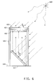
- H1 masters were made in the following manner. Two positive transparencies were first produced from FONT artwork spelling the letters AS in one case and the letter D in another case. These two digital graphic files were then optically transferred to film transparencies by a common phototypesetting process. An Agfa SelectSet 7000 Drum Imagesetter (Agfa, Regional Offices: Ridgefield park, Ridgefield Park, NJ 07660) was used. The first transparency of AS (601) was then placed ⁇ 1.27 cm (0.5 inches) above a 5x5 " ground glass diffuser (602) and ⁇ 1.27 cm (0.5 inches) below a fresh, unexposed DCG (dichromated gelatin) plate (603).
- a holographic exposure was then done by flood illuminating with a "Coherent Sabre Argon laser” (604) 3 watts at 488 nm from the ground glass side. More specifically, with the laser shuttered, the (15.24 cm x 15.24 cm) (6"x6") DCG plate was placed ⁇ 1.27 cm (0.5") above the transparency, and a portion of the 488nm laser beam was used as a reference beam to back illuminate the transparency and the diffuser for the holographic imaging (in addition to a portion being the object beam). See Figure 6.
- the ground glass diffuser used was a 3.175 mm (0.125 inch) thick window glass sand blasted on one side with Cyclone Manufacturing Brown Aluminum Oxide 150-180 grit.
- a ground glass diffuser can be made in several ways. In this case, sand blasting of one side of a 3.175 mm (1/8 inch) thick ordinary window glass was utilized. No directly transmitted light or specular reflections should remain after blasting.) Additional features shown in Figure 6 sre listed below:
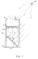
- the second transparency of the letter D (701) was holographically exposed in the same manner as given above for the letters AS, except that the second transparency was positioned further apart from a fresh, unexposed DCG plate (702).
- the second transparency was ⁇ 4 inches below the DCG plate and ⁇ 1.27 cm (.5 inches) above the ground glass diffuser. See Fig 7.
- Other features of the optical table are consistent with Figure 6.
- the D and the AS were positioned in the two transparencies such that when the two transparencies were overlayed in a certain way that the image seen in sequence is DAS.
- the exposed DCG (Dichromated Gelatin), a common holographic recording material, plate was placed in a Kodak fixer bath for 45-60 seconds. It was then placed immediately into 26.7 - 48.9°C (80-120 degree F) water for ⁇ 4 seconds and in another water bath at 26.7 - 48.9°C (80 to 120 degrees F) for 4 seconds. Next, it went into an 80% isopropyl alcohol 20% water bath at 54.4 - 60 °C (130-140 degrees F) for 4 seconds. It then went into 2 sequential 100% alcohol baths at 54.4 - 60 °C (130-140 F) for 2 seconds each. Then the exposed DCG plate was dipped into a final 100% alcohol bath for several seconds, which was sufficiently long enough to allow the plate to be slowly removed from the bath to promote even drainage and drying.
- the combined H1 (805) was then subjected to reverse conjugate illumination, holographically copied (as given supra) into a third DCG plate (801), and processed as above to afford a H2. More specifically, a third unexposed DCG plate (future H2) was placed in a position of being a virtual peudoscopic image of the letters AS (802) for this holographic copying, such that the AS image was recorded in the DCG essentially at the DCG-air interface surface of the DCG plate. This resulted in the D being recorded as a virtual image ⁇ 10.16 cm ( 4 inches) below the DCG plate (as a background image) upon holographic copying. See Figure 8.
- This example further illustrates another "puzzle” hologram according to the invention.
- This example involves the word “DuPont” and the DuPont logo - the word “DuPont” within an oval.
- This example is done in the same manner as for Example 1, except that the word “DuPont” is recorded as the first holographic image (which is a surface image) instead of the letters "AS" and the oval (alone, without the word DuPont) of the DuPont logo is recorded as the second holographic image - (either as a background image or a foreground image) instead of the letter "D”.
- An H2 master hologram is obtained using the methodology of Example 1.
- the word “DuPont” is visible and recognizable to the human eye in room light with the viewing angles and illumination being as in Example 1.
- Example 1 When the orange LED light as used in Example 1 is substituted for room-light, not only is the word "DuPont” visible and recognizable to a human eye but also the oval is visible and recognizable, and a viewer viewing the H2 master hologram along a normal line sees the famous DuPont oval as a complete integral image of this hologram.
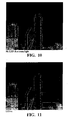
- Example 2 This example is similar to that of Example 2 with the difference being that a cityscape and parts of a letter E make-up the "puzzle” hologram instead of the word “DuPont” and an oval.
- This example is executed using the methodology of Example 1.
- the first holographic image is a cityscape made up of tall vertical box-like skyscrapers ( Figure10) and is recorded as a surface image. The last building on the right of the city is a narrow tall building. This cityscape image is viewable in room light (which is non-collimated).
- the second holographic image consists of 3 horizontal bars of thickness equal to that of the right hand building. The center horizontal bar is not as wide or as long as the top and bottom horizontal bars.
Landscapes
- Physics & Mathematics (AREA)
- General Physics & Mathematics (AREA)
- Engineering & Computer Science (AREA)
- Computer Security & Cryptography (AREA)
- Health & Medical Sciences (AREA)
- General Health & Medical Sciences (AREA)
- Toxicology (AREA)
- Holo Graphy (AREA)
Applications Claiming Priority (1)
| Application Number | Priority Date | Filing Date | Title |
|---|---|---|---|
| US73592305P | 2005-11-10 | 2005-11-10 |
Publications (2)
| Publication Number | Publication Date |
|---|---|
| EP1785782A2 true EP1785782A2 (fr) | 2007-05-16 |
| EP1785782A3 EP1785782A3 (fr) | 2008-09-17 |
Family
ID=37808362
Family Applications (1)
| Application Number | Title | Priority Date | Filing Date |
|---|---|---|---|
| EP06023486A Withdrawn EP1785782A3 (fr) | 2005-11-10 | 2006-11-10 | Hologramme de sécurité et procédés associés d'utilisation et de fabrication de celui-ci |
Country Status (4)
| Country | Link |
|---|---|
| US (1) | US20070103746A1 (fr) |
| EP (1) | EP1785782A3 (fr) |
| KR (1) | KR20070050389A (fr) |
| CN (1) | CN1983079A (fr) |
Families Citing this family (5)
| Publication number | Priority date | Publication date | Assignee | Title |
|---|---|---|---|---|
| US20110249307A1 (en) * | 2009-10-16 | 2011-10-13 | E. I. Du Pont De Nemours And Company | Hologram and associated methods of fabrication thereof and use in security/authentication applications |
| US8813184B2 (en) * | 2011-02-24 | 2014-08-19 | Empire Technology Development Llc | Authentication using mobile devices |
| TWI475253B (zh) * | 2012-05-04 | 2015-03-01 | Univ Nat Chiao Tung | 微型顯微鏡及其光學元件的製作方法 |
| WO2015065345A1 (fr) * | 2013-10-30 | 2015-05-07 | Empire Technology Development Llc | Génération et reconstruction d'une image holographique |
| US9779227B1 (en) * | 2014-10-24 | 2017-10-03 | Amazon Technologies, Inc. | Security system using keys encoded in holograms |
Citations (5)
| Publication number | Priority date | Publication date | Assignee | Title |
|---|---|---|---|---|
| US3506327A (en) | 1964-04-23 | 1970-04-14 | Battelle Development Corp | Wavefront reconstruction using a coherent reference beam |
| US3532406A (en) | 1966-03-30 | 1970-10-06 | Battelle Development Corp | Wavefront reconstruction with incoherent light |
| US3838903A (en) | 1965-10-29 | 1974-10-01 | Battelle Development Corp | Wavefront reconstruction |
| US3894787A (en) | 1969-05-19 | 1975-07-15 | Battelle Development Corp | Holograms |
| US6687031B1 (en) * | 1999-07-09 | 2004-02-03 | Dai Nippon Printing Co., Ltd. | Holographic display element and method of making the same |
Family Cites Families (11)
| Publication number | Priority date | Publication date | Assignee | Title |
|---|---|---|---|---|
| US4067638A (en) * | 1971-12-08 | 1978-01-10 | Canon Kabushiki Kaisha | Multi-color holographic stereograms |
| US5473447A (en) * | 1994-02-14 | 1995-12-05 | Polaroid Corporation | Heads-up and heads-down displays employing holographic stereograms |
| US5642884A (en) * | 1996-03-27 | 1997-07-01 | Polaroid Corporation | Holographic image reconstruction puzzle |
| CN1153100C (zh) * | 1997-03-18 | 2004-06-09 | 松下电器产业株式会社 | 光学式显示装置 |
| JP4270415B2 (ja) * | 1998-11-26 | 2009-06-03 | 大日本印刷株式会社 | カラーホログラム |
| PL354040A1 (en) * | 1999-06-01 | 2003-12-15 | De La Rue International Limitedde La Rue International Limited | Security device |
| GB0016358D0 (en) * | 2000-07-03 | 2000-08-23 | Optaglio Ltd | Optical device |
| JP4646097B2 (ja) * | 2001-07-18 | 2011-03-09 | 大日本印刷株式会社 | 付加情報の付いたホログラム記録フィルム及びその記録方法 |
| CA2438395A1 (fr) * | 2001-12-20 | 2003-07-03 | Seiko Epson Corporation | Matiere enregistree comprenant une mesure de prevention contre la contrefacon |
| US7576898B2 (en) * | 2004-02-17 | 2009-08-18 | E. I. Du Pont De Nemours And Company | Method for using a deep image hologram as a security device and a deep image hologram |
| US20060082850A1 (en) * | 2004-10-18 | 2006-04-20 | Weaver Samuel P | Covert surface relief hologram design, fabrication and optical reconstruction for security applications |
-
2006
- 2006-11-06 US US11/593,339 patent/US20070103746A1/en not_active Abandoned
- 2006-11-10 KR KR1020060110975A patent/KR20070050389A/ko not_active Withdrawn
- 2006-11-10 CN CNA2006101464757A patent/CN1983079A/zh active Pending
- 2006-11-10 EP EP06023486A patent/EP1785782A3/fr not_active Withdrawn
Patent Citations (5)
| Publication number | Priority date | Publication date | Assignee | Title |
|---|---|---|---|---|
| US3506327A (en) | 1964-04-23 | 1970-04-14 | Battelle Development Corp | Wavefront reconstruction using a coherent reference beam |
| US3838903A (en) | 1965-10-29 | 1974-10-01 | Battelle Development Corp | Wavefront reconstruction |
| US3532406A (en) | 1966-03-30 | 1970-10-06 | Battelle Development Corp | Wavefront reconstruction with incoherent light |
| US3894787A (en) | 1969-05-19 | 1975-07-15 | Battelle Development Corp | Holograms |
| US6687031B1 (en) * | 1999-07-09 | 2004-02-03 | Dai Nippon Printing Co., Ltd. | Holographic display element and method of making the same |
Non-Patent Citations (2)
| Title |
|---|
| DITTMANN J ET AL: "Hologram watermarks for document authentications", PROCEEDINGS INTERNATIONAL CONFERENCE ON INFORMATION TECHNOLOGY:CODING AND COMPUTING, XX, XX, 2 April 2001 (2001-04-02), pages 60 - 64, XP002973218 * |
| E. N. LEITH; J. UPATNIEKS: "Photography by Laser", SCIENTIFIC AMERICAN, vol. 212, no. 6, June 1965 (1965-06-01), pages 24 - 35 |
Also Published As
| Publication number | Publication date |
|---|---|
| KR20070050389A (ko) | 2007-05-15 |
| US20070103746A1 (en) | 2007-05-10 |
| EP1785782A3 (fr) | 2008-09-17 |
| CN1983079A (zh) | 2007-06-20 |
Similar Documents
| Publication | Publication Date | Title |
|---|---|---|
| US4094575A (en) | Holographic article and process for making same | |
| Ackermann et al. | Holography: a practical approach | |
| EP0064067B2 (fr) | Procedè de gèneration de composition graphique diffractive | |
| US4717221A (en) | Diffractive color and texture effects for the graphic arts | |
| US3515452A (en) | Forming a hologram of a subject recorded on an integral photograph with incoherent light | |
| EA017886B1 (ru) | Голографический защитный элемент | |
| US7576898B2 (en) | Method for using a deep image hologram as a security device and a deep image hologram | |
| GB2119950A (en) | Improvements in or relating to holograms | |
| CZ200355A3 (cs) | Optická aparatura | |
| US4629282A (en) | Diffractive color and texture effects for the graphic arts | |
| US5499116A (en) | Encoded hologram for producing a machine readable image and a human readable image | |
| US6844945B2 (en) | Hologram having authenticating information recorded therein | |
| US7710623B2 (en) | Security hologram, method of recording same, and method of using same wherein the holographic imaging includes a single coherent beam of electromagnetic radiation in combination with a Lloyd's mirror to provide both reference and object beams | |
| JPS6037475B2 (ja) | 秘密情報の処理方法 | |
| EP1785782A2 (fr) | Hologramme de sécurité et procédés associés d'utilisation et de fabrication de celui-ci | |
| US4918469A (en) | Diffractive color and texture effects for the graphic arts | |
| JP2002208053A (ja) | 有価証券等の光学パターン表示体、及び後で個性付与又は情報を記録することができる光学パターン表示体の製造方法 | |
| US3942861A (en) | Full view hologram | |
| GB2149532A (en) | Improvements in or relating to holograms | |
| US3658404A (en) | Complex wave modifying structure holographic system | |
| US20100290099A1 (en) | Method and Apparatus for Creating and Displaying a Radially Multiplexed Hologram | |
| JP2002341733A (ja) | 表示体およびそれからの情報再生方法 | |
| JP2000250389A (ja) | 偽造防止媒体 | |
| Rossing et al. | Holography | |
| WO2006077444A2 (fr) | Hologrammes de securite |
Legal Events
| Date | Code | Title | Description |
|---|---|---|---|
| PUAI | Public reference made under article 153(3) epc to a published international application that has entered the european phase |
Free format text: ORIGINAL CODE: 0009012 |
|
| AK | Designated contracting states |
Kind code of ref document: A2 Designated state(s): AT BE BG CH CY CZ DE DK EE ES FI FR GB GR HU IE IS IT LI LT LU LV MC NL PL PT RO SE SI SK TR |
|
| AX | Request for extension of the european patent |
Extension state: AL BA HR MK YU |
|
| PUAL | Search report despatched |
Free format text: ORIGINAL CODE: 0009013 |
|
| AK | Designated contracting states |
Kind code of ref document: A3 Designated state(s): AT BE BG CH CY CZ DE DK EE ES FI FR GB GR HU IE IS IT LI LT LU LV MC NL PL PT RO SE SI SK TR |
|
| AX | Request for extension of the european patent |
Extension state: AL BA HR MK RS |
|
| 17P | Request for examination filed |
Effective date: 20090317 |
|
| 17Q | First examination report despatched |
Effective date: 20090417 |
|
| AKX | Designation fees paid |
Designated state(s): DE FR GB |
|
| STAA | Information on the status of an ep patent application or granted ep patent |
Free format text: STATUS: THE APPLICATION IS DEEMED TO BE WITHDRAWN |
|
| 18D | Application deemed to be withdrawn |
Effective date: 20100916 |