EP1785952A1 - Dispositif d'alimentation de pièces de monnaie - Google Patents
Dispositif d'alimentation de pièces de monnaie Download PDFInfo
- Publication number
- EP1785952A1 EP1785952A1 EP06021857A EP06021857A EP1785952A1 EP 1785952 A1 EP1785952 A1 EP 1785952A1 EP 06021857 A EP06021857 A EP 06021857A EP 06021857 A EP06021857 A EP 06021857A EP 1785952 A1 EP1785952 A1 EP 1785952A1
- Authority
- EP
- European Patent Office
- Prior art keywords
- coin
- rotating disk
- concave portion
- coins
- disk
- Prior art date
- Legal status (The legal status is an assumption and is not a legal conclusion. Google has not performed a legal analysis and makes no representation as to the accuracy of the status listed.)
- Granted
Links
Images








Classifications
-
- G—PHYSICS
- G07—CHECKING-DEVICES
- G07D—HANDLING OF COINS OR VALUABLE PAPERS, e.g. TESTING, SORTING BY DENOMINATIONS, COUNTING, DISPENSING, CHANGING OR DEPOSITING
- G07D9/00—Counting coins; Handling of coins not provided for in the other groups of this subclass
- G07D9/008—Feeding coins from bulk
Definitions
- the present invention relates to a coin feeding device, which separates coins of multiple denominations different in diameter one by one and delivers them to the next process.
- coin used in the present specification includes a monetary coin, token and medal or the like, and its shape includes circular and polygonal forms.
- Patent Document 1 Japanese Patent Application Laid-Open No. 8-171666 (Page 2, FIG.1)
- Patent Document 2 Japanese Utility Model Laid-Open No. 57-50776 (Pages 2 to 7, FIG. 4)
- the separation of the coins for each piece is regulated just by the intervals of the pins.
- the maximum diameter coin and the minimum diameter coin are large, for example, in the case of Sterling Pound, the maximum diameter is 28.5 millimeter of a two pound coin and the minimum diameter is 18 millimeter of a five pence coin.
- the fan-shaped concave portion is a concave portion of the size corresponding to the coin of a predetermined diameter, that is, the coin of one type, when the coins of multiple types different in diameter are mixed and input, the fan-shaped concave portion is ill-suited for separating the coins of any types one by one and feeding them to the next process.
- An object of the present invention is to provide a coin feeding device capable of separating the coins one by one and feeding them to the next process even when the coins of multiple denominations different in diameter coexist, and at the same time, providing a preventive structure in which the rotating disc does not feed the coins by connection two or more pieces in a radial direction, so that highly reliable coin processing can be performed at the next process.
- a coin feeding device in which coins (110) are held on a separating concave portion (138) disposed on the upper face of the rotating disk (112), and after being separated one by one, they are fed to the next process, comprises: a pushing-out disk provided on the upper face of the rotating disk and formed among projection portions in which the separating concave portion extends in the multiple radial patterns; and a moving body provided at one side of the separating concave portion and operating so as to push out the coin from the separating concave portion when fed to the next process, wherein the protruded portion protruded upward from the upper face of the pushing-out disk is provided at the coin pushing-ahead portion formed at one side of the separating concave portion of the peripheral edge of the projection portion and a concave portion exit portion of the opposite side.
- a concave portion is a portion in which one coin only is seatable, and therefore, both two pieces of the coins having the minimum diameter are not held together in the separating concave portion.
- the moving body which forms the concave portion moves so as to push out the coin from the concave portion.
- the coins which are held in the separating concave portion only are certainly fed out one by one, and the coin processing at the next process, for example, the coin processing such as denomination discrimination and the like can be performed with high accuracy.
- the invention as claimed in claim 2 is a further limitation of the invention according to claim 1.
- the coin feeding device according to claim 2 is a coin feeding device provided with an elastic baffle plate having its top end contacting an outer peripheral portion upper face of the rotating disk.
- the invention according to claim 3 is a further limitation of the invention according to any one of claims 2 to 3.
- the coin feeding device according to claim 3 is a coin feeding device provided with the baffle plate having its top end contacting also the peripheral edge of the projection portion.
- the top end of the baffle plate slides not only with the upper face of the rotating disk, but also the peripheral edge of the projection portion of the pushing-out disk, and is installed so as to occupy the outer peripheral portion of the rotating disk in a sufficient scale, and therefore, almost all the coins trying to ride on the normal coil can be effectively excluded.
- the invention according to claim 4 is a further limitation of the invention according to any one of claims 2 to 3.
- the coin feeding device according to claim 4 is a coin feeding device, in which the baffle plate is an elastic plate formed by synthetic resin. In this configuration, the baffle plate can be easily obtained, which is formed by synthetic resin, and is low in price, and can obtain a sufficient rebound elastic force.
- the invention according to claim 5 is a further limitation of the invention according to any one of claims 2 to 4.
- the coin feeding device according to claim 5 is a coin feeding device, in which the baffle plate is disposed in the rotating route of the rotating disk at a position before the moving body starts a coin pushing-ahead operation.
- the invention according to claim 6 is a further limitation of the invention according to any one of claims 1 to 5.
- the coin pushing-out device according to claim 6 is a coin feeding device in which a R shaped chamfering portion is provided in the outer peripheral portion of the projection portion of the pushing-out disk in a predetermined range.
- the pushing-out disk is chamfered in the shape of R in its outer peripheral edge portion in a predetermined range, and therefore, the coin that sometimes ends up riding on the outer peripheral edge portion of the pushing-out disk by a centrifugal force and the like is easily slipped off by this R-shaped chamfering portion.
- a trouble such as a few pieces of the coins of a small diameter and the like being fed out while moving on the outer peripheral portion of the rotating disk is eliminated, thereby improving a processing accuracy of coin discrimination and the like performed at the next process.
- a coin feeding device in which coins (110) are held on a separating concave portion (138) disposed on the upper face of the rotating disk (112), and after being separated one by one, they are fed to the next process, comprises: a pushing-out disk provided on the upper face of the rotating disk and formed among projection portions in which the separating concave portions extend in multiple radial patterns; and a moving body provided at one side of the separating concave portion and operating so as to push out the coin from the separating concave portion when fed to the next process, wherein the protruded portion protruded upward from the upper face of the pushing-out disk is provided at the coin pushing-ahead portion formed at one side of the separating concave portion of the peripheral edge of the projection portion and a concave portion exit portion of the opposite side, and further, the elastic baffle plate where its top end contacts the outer peripheral portion top face of the rotating disk is disposed in the rotating route of the rotating disk, and moreover, the baffle plate also contacts the peripheral edge of the projection portion, and at
- the present embodiment is a coin feeding device of a coin processing device which accommodates eight types of coins such as 2 Euro, 1 Euro, 50 Cent, 20 Cent, 10 Cent, 5 Cent, 2 Cent, and 1 Cent which are the currency of the currencies of European community, and retains them for each denomination, and pays the predetermined number of coins of the predetermined denominations based on a delivery support.
- eight types of coins such as 2 Euro, 1 Euro, 50 Cent, 20 Cent, 10 Cent, 5 Cent, 2 Cent, and 1 Cent which are the currency of the currencies of European community, and retains them for each denomination, and pays the predetermined number of coins of the predetermined denominations based on a delivery support.
- a coin processing device 100 includes a coin delivery device 101, a denomination discriminating device 102, a coin transfer device 103, and an unillustrated coin selecting device provided inside the coin transfer device 103.
- the coin feeding device 100 is provided with a rotating disk 105 which separates and feeds the coins one by one, and by the rotating disk 105, the coins are fed one by one to a denomination discriminating device 102.
- a coin 110 is fed to the denomination discriminating device 102 through a coin delivery opening 106 provided on the upper part position of the coin feeding device 101.
- authenticity of the coins and discrimination of the denominations are performed by a magnetic sensor and the like though not illustrated, and after that, the coins are sent to the transfer device 103 of the next process, and in the midst of the transferring the coins in the predetermined route, they are separated according to denomination by the coin selecting device of the mechanism that opens and closes a predetermined gate.
- the coin feeding device 100 will be further described with reference to FIGS. 2 and 4.
- the coin feeding device 100 includes the rotating disk 105, a coin retaining ball 104 for retaining the coil, and a cylinder shaped retaining ring 107 positioned so as to surround the rotating disk 105 at the underneath of the retaining ball 104.
- the coins of plural denominations inputted from a coin inputting port are guided and dropped into the retaining portion at the underneath from an opening port of the retaining ball 104 and are retained in the shape of a pile.
- the rotating disk 105 comprises a separating concave portion 113 which accommodates the coins one by one, and is installed in an inclined manner at the bottom of the retaining ring 107 at a predetermined angle, and is rotated in a constant direction at a predetermined velocity, that is, counter-clockwise shown by an arrow mark G in the embodiment.
- the rotating disk 105 comprises a rotating circular plate 111 which becomes a base and a pushing out disk 112 coaxially fixed with the rotating circular plate 111 on the upper face 111S of this rotating circular plate 111 and made of a Y shaped plate having three concave portions divided at approximately equal intervals by the projection portion 115.
- An approximately semi-circular separating concave portion 113 is formed on the upper surface of the rotating circular plate 111 by a space between the projection portion 115 and the projection portion 115 of the pushing-out disk 112 and a moving body 117 to be described later.
- a depth of the separating concave portion 113 in other words, a thickness of the pushing-out disk 112 is formed slightly shallower than the thinnest coin thickness from among the eight types of denominations.
- the plate is not limited to the Y shaped plate, but may be a plate in the shape of multiple projection portions formed in a radial pattern. Further, the rotating circular plate 111 and the plate, that is, the pushing-out disk 112 can be integrally formed by resin having metal or abrasion resistance.
- the separating concave portion 113 between the projection portions 115 is disposed with the moving body 117 which performs a pivot motion with a pivot axis 120 as a support point.
- the separating concave portion 113 is formed as an approximately semi-circular separating concave portion on the rotating disk 111 by this moving body 117 and the concave portion between the projection portions 115.
- the other side of the concave portion is formed with a coin pushing-ahead portion 121 in which a slightly concaved concavity is formed, and which works such that the coin 110 is accommodated in this concavity and pressed and transferred.
- an arched receiving portion 118 for receiving the moving body 117 is provided in the separating concave portion 113.
- the separating concave portion 113 is set such that two pieces lined up of the smallest diameter coins are not accommodated, but only one piece of the largest diameter coin is accommodated.
- the separating concave portion 113 has a size as displayed by an assumed line circle 160, and is set to a size unable to accommodate two pieces of the minimum diameter coins 110s inside this assumed line circle 160, that is, a size below two times the diameter of the minimum diameter coin 110s.
- the separating concave portion 113 will never accommodate two pieces of the minimum diameter coins 110s lined up in the diameter direction of the rotating disk 105.
- the moving body 117 is usually located in a resting state shifted to one side of the concavity so as to form the separating concave portion 113, and when moved to a predetermined position by pivoting motion, feeds the held coin 110 to the peripheral direction of the rotating plate 111.
- the movement of the moving body 117 at this predetermined position is performed in the rotating route of the rotating disk 105 slightly in the downstream vicinity of the coin delivery opening 106 formed so that the coin can pass through to the denomination discriminating device 102 at the upper part of the retaining ring 107.
- the moving body 117 When passing though the opening 106, the moving body 117 performs a return back operation so as to be accommodated in the receiving portion 118 formed at one side of the concavity.
- Such movement of the moving body 117 is made possible by the groove cam and the like by utilizing the rotating movement of the circular plate 111. That is, the midpoint of the moving body 117 is fixed and provided with a pin 122, and this pin 112 is inserted into an arched pass-through hole 123, which is formed with the pivot axis 120 as a center, and which is formed in the rotating circular plate 111 of the rotating disk 105. Further, a drive mechanism may be used, in which this pin 122 is allowed to be slidably inserted into a groove cam provided at the underside of the rotating circular plate 111 through a driven body such as a roller and the like. The rotating disk 105 is rotated by an electric motor 124.
- the rotation of the electric motor 124 is transferred to a reduction gear 126 formed at the underneath peripheral surface of the circular plate 111 shown in FIG. 4 through a speed reducer, and the rotating disk 105 is rotated at the predetermined speed.
- a knife shaped coin receiving portion 127 for receiving the coil 110 pushed out by the moving body 117 operated at the predetermined position.
- a rotating wheel 128 for feeding the coin guided by the receiving portion 127.
- the rotating disk 105 configured as described above, the coins bulk-loaded and existing in the holding portion are agitated, and moreover, each piece of the coins is held one by one by the separating concave portion 113 and moved upward, and at a point of time when it comes to a predetermined position above the rotating center, it is pushed out in a peripheral direction from the separating concave portion 113 by the moving body 117.
- the pushed out coin passes through the opening portion 106, and fed into the denomination discriminating device 102 through the coin receiving portion 127, and after the coin is discriminated according to the denomination, it is further sent to the transfer device 104 by the rotating wheel 128.
- the projection portion 115 of the pushing out disk 112 is provided with a protruded portion 130 formed and bent upward.
- a rotating disk 105 provided with such a protruded portion 130 at the top end is the characteristic of the present invention.
- the protruded portion 130 exists in order to separate the held coin protruded from the separating concave portion 113 adapted approximately to the thinnest coin in depth from another coin so that another coin is not hooked and lifted. Further, this protruded portion is a peripheral edge of the projection portion 115, and is positioned by facing a concave portion exit of the opposite side of the coin pushing ahead portion 121 in the separating concave portion 113.
- the separating concave portion 113 in which the coin enters is actually a concave portion formed between the inner edge of this moving body 117 and the coin pushing ahead portion 121, and is a flat groove opened in the upper surface side and the peripheral surface side.
- the depth of the separating concave portion 113 in other words, the thickness of the pushing out disk 112 for pushing out the coin is, as described above, formed slightly thinner than the thinnest coin thickness among the eight denominations.
- the protruded portion 130 exists. Further, this protruded portion 130 is a peripheral edge of the projection portion 115, and is positioned by facing a concave portion exit of the opposite side of the coin pushing ahead portion 121 in the separating concave portion 113. As shown in FIG. 7, in the separating concave portion 113, when the coin 110a is entered, a gap is created between the coin and the concave portion exit edge portion, and there is the possibility that another coin partially enters there. Thus, another coin 110b is easily hooked by the edge of the held coin 110a.
- the coin 110b receives an action as if to float in a direction to the upper surface of the rotating disk 105 by the protruded portion 130.
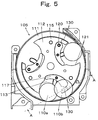
- the floated state of the coin 110b is shown in FIGS. 5 and 6.
- the top coin 110b is pushed up always by the protruded portion 130, that is, the bent portion, and between the upper surface of the rotating plate 111 and the underneath of the top coin 110b, there is a gap formed into which the coin 110a positioned in the separating concave portion 113 can advance.
- the coin 110a inside the separating concave portion 113 does not push the coin 110b by the edge 125 of the coin, but slips under the coin 110b.
- this protruded portion 130 has been taken as a bent portion provided by bending upward the top end of the projection portion 115, it may be a structure providing a protruded portion by making the thickness of a plate which is a material of the pushing out disk 112 solidly thick at the top end portion, or the structure providing a protruded portion of a separate body at the top end portion. As a protruded portion, it may function to float the coin on the rotating disk surface.
- the top end of the projection portion 130 is formed on the arched end surface portion in which the inner side inner surface of the moving body 117 and the coin push ahead portion 121 are matched so as to take charge of a part of the circle 160 of the assumed line defining the size of the separating concave portion.
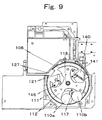
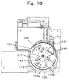
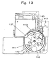
- FIGS. 9 to 16 another configuration may be suitable as shown in FIGS. 9 to 16, wherein a flexible coin separation baffle plate 140 is provided so as to slot into a rotating route of the rotating disk 105, and moreover, the baffle plate is put into a sliding state with the upper surface of the rotating disk.
- the baffle plate 140 having elasticity is extendingly disposed in the rotating route so that the plate 140 hangs from above on the upper surface of the rotating disk 105, and moreover, the top end of the baffle plate 140 is provided so as to contact the upper surface of the rotating disk 105, that is, the upper surface 111S of the rotating circular plate 111.
- the baffle plate 140 can also adapt a synthetic resin member, for example, an elastic plate integrally formed by polycarbonate and the like. Further, since the baffle plate 140 is in friction with the rotating disk, if the material is a resin material having abrasion resistance, a life span can be improved, and this is preferable.
- the baffle plate 140 is attached to a holding ball 104 by a support arm 141.
- the top end of the baffle plate 140 contacts not only the upper surface of the rotating circular plate 111, but also the peripheral edge of the projection portion 115 of the pushing out disk, and is disposed so as to approximately occupy the outer peripheral portion of the rotating disk 105.
- the coin 110b hits against the baffle plate 140, and is pushed and bent.
- the coin 110b conversely receives a rebound elastic force from the baffle plate 140, and is repelled and dropped off. In this way, the connected feeding of the coins is prevented.
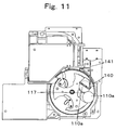
- FIGS. 9 to 14 sequentially show a series of these operations.
- the position at which the baffle plate 140 is located is set in advance at a position hitting against the coin 110b at a point of time earlier than the moving body 117 moves to such positions as shown in FIGS. 13 to 14 and starts moving so as to push out the held coin.
- the coin 110b hooked by the held coin 110a and arriving at this position is separated and dropped in advance by the elastic force of the baffle plate 140 as shown in FIG. 12 before the moving body 117 starts operating.
- the process of lifting up the held coin 110a by the moving body 117 is not affected. In this way, only one piece of the coin can be fed to the next process.
- the baffle plate 140 has been assumed to be an elastic plate having an elastic force by itself, another configuration can be adopted in which the plate member biased to a direction reverse to the rotating direction by biasing means such as a spring and the like is disposed, and opposing to the pushing force of the coin, a snapping force is applied to the coin from the plate member.
- biasing means such as a spring and the like
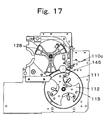
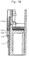
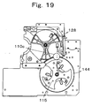
- a chamfering portion 145 in the shape of R in the predetermined range in the peripheral edge of the projection portion 115 of the pushing out disk 112 as shown in the rotating disk of FIG. 4 is also one of the important methods.
- This embodiment is shown in FIGS. 17 and 18.
- the chamfering portion 145 is formed in the predetermined range from the position where the projection portion 115 is located, and is not allowed to be extended to the portion close to the coin pushing ahead portion 121. This is because if the chamfering portion 145 exists close till the coin pushing ahead portion 121, the coin is prone to escape by the chamfering portion 145 when entering the separating concave portion 113, and the coin entrance is prevented from being affected.
- the coin 110c is allowed to easily slide off by the R shaped chamfering portion 145, and therefore, even if the coin 110c is rode on the outer peripheral portion, it is not dropped off nor is it transferred into the denomination discriminating device 103, and the entering of two pieces of the coins will not occur.
- the normal coin enters, and therefore, the accurate discrimination of the coins one by one is executed, so that the performance of the coin processing device can be highly maintained.
- the rotating disk 105 detects the input of the coin, and is automatically or rotated full-time. By the rotation of the rotating disk 105, the coin 110 is agitated by the projection portion 115, and advances into the separating concave portion 113. At the position other than the vicinity of the coin denomination discriminating device 103, the moving body 117 is positioned at the receiving portion 118, and hence it is at the receiving position.
- the coin 110 is held one piece only at the separating concave portion 113 which is defined by the pushing ahead portion 121 of the projection portion 115 and the arched surface of the moving body 117.
- the separating concave portion 113 formed slightly deeper in depth than the diameter of the maximum diameter coin holds one piece only of the maximum diameter coin.
- the minimum diameter coin is unable to advance two pieces into a diameter direction of the rotating disk 105.
- the concave portion 113 is unable to line up two pieces of the minimum diameter coins in the peripheral direction of the rotating disk 105. Consequently, the minimum diameter coin is held one piece only in the separating concave portion 113.
- the coin 110 held in the concave portion 113 is moved to the denomination discriminating device 104 side by the rotation of the rotating disk 105.
- the coin 110 is moved from downward to upward.
- the coin 110 is pushed and moved by the pushing ahead portion 121, and almost no force is applied to the moving body 117.
- the moving body 117 is pivotally moved clockwise with the axis 120 as a support point.
- the moving body 117 pushes the coin 110 positioned at the separating concave position 113 to the radial direction of the rotating disk 105 from the lateral side, and therefore, the coin 110 is pushed out from the separating concave portion 113.
- the coin 110 passes through the opening 106.
- the coinhaving passed through the opening is further fed into the denomination discriminating device 103 by the rotation of the wheel 128 inside the device, and is transferred to the process of denomination discrimination.
- a coin feeding operation is performed in a state in which the rotating disk definitely holds the coin one piece only in the separating concave portion, and therefore the transferring of multiple coins to the next coin processing portion such as denomination discriminating device and the like can be prevented, thereby realizing a coin processing device capable of performing highly accurate discrimination.
Landscapes
- Physics & Mathematics (AREA)
- General Physics & Mathematics (AREA)
- Testing Of Coins (AREA)
Applications Claiming Priority (1)
| Application Number | Priority Date | Filing Date | Title |
|---|---|---|---|
| JP2005304970A JP4844081B2 (ja) | 2005-10-19 | 2005-10-19 | コイン送り出し装置 |
Publications (2)
| Publication Number | Publication Date |
|---|---|
| EP1785952A1 true EP1785952A1 (fr) | 2007-05-16 |
| EP1785952B1 EP1785952B1 (fr) | 2008-05-14 |
Family
ID=37617146
Family Applications (1)
| Application Number | Title | Priority Date | Filing Date |
|---|---|---|---|
| EP06021857A Active EP1785952B1 (fr) | 2005-10-19 | 2006-10-18 | Dispositif d'alimentation de pièces de monnaie |
Country Status (4)
| Country | Link |
|---|---|
| US (1) | US7654891B2 (fr) |
| EP (1) | EP1785952B1 (fr) |
| JP (1) | JP4844081B2 (fr) |
| DE (1) | DE602006001191D1 (fr) |
Cited By (3)
| Publication number | Priority date | Publication date | Assignee | Title |
|---|---|---|---|---|
| EP2819105A1 (fr) * | 2013-06-26 | 2014-12-31 | Innovative Technology Limited | Mécanisme de transport de pièces de monnaie |
| CN106780939A (zh) * | 2016-12-15 | 2017-05-31 | 浙江海洋大学 | 一种硬币筛分装置 |
| EP3686851A1 (fr) * | 2019-01-28 | 2020-07-29 | Asahi Seiko Co., Ltd. | Dispositif de détection et de séparation de pièces de monnaie |
Families Citing this family (3)
| Publication number | Priority date | Publication date | Assignee | Title |
|---|---|---|---|---|
| JP5274549B2 (ja) * | 2008-04-24 | 2013-08-28 | グローリー株式会社 | 硬貨処理装置 |
| JP6650114B2 (ja) * | 2016-10-05 | 2020-02-19 | 住友電装株式会社 | 電線ガイド装置 |
| JP6934676B2 (ja) | 2019-01-28 | 2021-09-15 | 旭精工株式会社 | 硬貨処理装置の硬貨分離送出装置 |
Citations (3)
| Publication number | Priority date | Publication date | Assignee | Title |
|---|---|---|---|---|
| GB2308485A (en) * | 1995-12-19 | 1997-06-25 | Universal Sales Co Ltd | Coin dispenser |
| EP0959437A2 (fr) * | 1998-05-21 | 1999-11-24 | Asahi Seiko Co. Ltd. | Dispositif pour distribuer des pièces de monnaie |
| GB2353129A (en) * | 1999-06-25 | 2001-02-14 | Asahi Seiko Co Ltd | Coin dispensing apparatus with adjustable coin apertures |
Family Cites Families (7)
| Publication number | Priority date | Publication date | Assignee | Title |
|---|---|---|---|---|
| US1813296A (en) * | 1927-03-14 | 1931-07-07 | Arthur C Kidwell | Coin separator |
| US3233778A (en) * | 1964-01-16 | 1966-02-08 | Whirlpool Co | Pellet dispenser |
| JPS49102794A (fr) * | 1973-01-31 | 1974-09-27 | ||
| JPS5750776A (en) | 1980-09-11 | 1982-03-25 | Nippon Acchakutanshi Seizo Kk | Contact for pressure contact connector and method of producing same |
| US4316539A (en) * | 1980-12-10 | 1982-02-23 | Rca Corporation | Video disc caddy |
| JPH08171666A (ja) | 1994-12-16 | 1996-07-02 | Odawara Kiki:Kk | 硬貨選別収納装置 |
| US7255639B2 (en) * | 2004-07-15 | 2007-08-14 | Asahi Seiko Kabushiki Kaisha | Coin delivery device and separator device for a coin processing apparatus |
-
2005
- 2005-10-19 JP JP2005304970A patent/JP4844081B2/ja not_active Expired - Lifetime
-
2006
- 2006-10-18 EP EP06021857A patent/EP1785952B1/fr active Active
- 2006-10-18 US US11/582,935 patent/US7654891B2/en active Active
- 2006-10-18 DE DE602006001191T patent/DE602006001191D1/de active Active
Patent Citations (3)
| Publication number | Priority date | Publication date | Assignee | Title |
|---|---|---|---|---|
| GB2308485A (en) * | 1995-12-19 | 1997-06-25 | Universal Sales Co Ltd | Coin dispenser |
| EP0959437A2 (fr) * | 1998-05-21 | 1999-11-24 | Asahi Seiko Co. Ltd. | Dispositif pour distribuer des pièces de monnaie |
| GB2353129A (en) * | 1999-06-25 | 2001-02-14 | Asahi Seiko Co Ltd | Coin dispensing apparatus with adjustable coin apertures |
Cited By (6)
| Publication number | Priority date | Publication date | Assignee | Title |
|---|---|---|---|---|
| EP2819105A1 (fr) * | 2013-06-26 | 2014-12-31 | Innovative Technology Limited | Mécanisme de transport de pièces de monnaie |
| CN106780939A (zh) * | 2016-12-15 | 2017-05-31 | 浙江海洋大学 | 一种硬币筛分装置 |
| CN106780939B (zh) * | 2016-12-15 | 2019-04-05 | 浙江海洋大学 | 一种硬币筛分装置 |
| EP3686851A1 (fr) * | 2019-01-28 | 2020-07-29 | Asahi Seiko Co., Ltd. | Dispositif de détection et de séparation de pièces de monnaie |
| CN111489484A (zh) * | 2019-01-28 | 2020-08-04 | 旭精工株式会社 | 硬币分离检测装置 |
| CN111489484B (zh) * | 2019-01-28 | 2021-12-28 | 旭精工株式会社 | 硬币分离检测装置 |
Also Published As
| Publication number | Publication date |
|---|---|
| JP4844081B2 (ja) | 2011-12-21 |
| US20070087676A1 (en) | 2007-04-19 |
| US7654891B2 (en) | 2010-02-02 |
| JP2007114973A (ja) | 2007-05-10 |
| EP1785952B1 (fr) | 2008-05-14 |
| DE602006001191D1 (de) | 2008-06-26 |
Similar Documents
| Publication | Publication Date | Title |
|---|---|---|
| EP2500874B1 (fr) | Appareil de séparation et de transfert de pièces de monnaie | |
| CA2011274C (fr) | Mecanisme de triage de pieces de monnaie | |
| EP0557428B1 (fr) | Mecanisme de triage de pieces de monnaie | |
| KR100838193B1 (ko) | 경화의 금종별 분류 장치 | |
| EP2261866A2 (fr) | Appareil de tri de pièces et système de réception de pièces | |
| US7661521B2 (en) | Coin selector | |
| EP1657685B1 (fr) | Système de distinction de dénomination dans un appareil de traitement de pièces de monnaie | |
| EP1918888B1 (fr) | Appareil d'alimentation en pièces | |
| JP4780494B2 (ja) | 硬貨金種判別装置 | |
| EP1785952B1 (fr) | Dispositif d'alimentation de pièces de monnaie | |
| EP1791095B1 (fr) | Dispositif de distribution de pièces et dispositif de distribution de pièces d'appareil de traitement de pièces | |
| EP3686851A1 (fr) | Dispositif de détection et de séparation de pièces de monnaie | |
| JP5830749B2 (ja) | 硬貨処理装置 | |
| US6615969B2 (en) | Mechanical coin checker | |
| US8172654B2 (en) | Coin processing machine with pivoting alignment finger | |
| US7883401B1 (en) | Coin plate with diverter finger | |
| JP5309965B2 (ja) | 価値媒体処理装置 | |
| JP2012190334A5 (fr) | ||
| JP6182766B2 (ja) | コインセレクタ | |
| JP2011170903A (ja) | 硬貨の金種判別装置 | |
| EP1603084A1 (fr) | Dispositif de distribution d'objets en forme de disque | |
| KR101028445B1 (ko) | 코인 선별 장치 및 코인 선별 계수 장치 | |
| JP2012160087A5 (fr) |
Legal Events
| Date | Code | Title | Description |
|---|---|---|---|
| PUAI | Public reference made under article 153(3) epc to a published international application that has entered the european phase |
Free format text: ORIGINAL CODE: 0009012 |
|
| AK | Designated contracting states |
Kind code of ref document: A1 Designated state(s): AT BE BG CH CY CZ DE DK EE ES FI FR GB GR HU IE IS IT LI LT LU LV MC NL PL PT RO SE SI SK TR |
|
| AX | Request for extension of the european patent |
Extension state: AL BA HR MK YU |
|
| 17P | Request for examination filed |
Effective date: 20070509 |
|
| GRAP | Despatch of communication of intention to grant a patent |
Free format text: ORIGINAL CODE: EPIDOSNIGR1 |
|
| AKX | Designation fees paid |
Designated state(s): DE FR GB |
|
| GRAS | Grant fee paid |
Free format text: ORIGINAL CODE: EPIDOSNIGR3 |
|
| GRAA | (expected) grant |
Free format text: ORIGINAL CODE: 0009210 |
|
| AK | Designated contracting states |
Kind code of ref document: B1 Designated state(s): DE FR GB |
|
| REG | Reference to a national code |
Ref country code: GB Ref legal event code: FG4D |
|
| REF | Corresponds to: |
Ref document number: 602006001191 Country of ref document: DE Date of ref document: 20080626 Kind code of ref document: P |
|
| PLBE | No opposition filed within time limit |
Free format text: ORIGINAL CODE: 0009261 |
|
| STAA | Information on the status of an ep patent application or granted ep patent |
Free format text: STATUS: NO OPPOSITION FILED WITHIN TIME LIMIT |
|
| 26N | No opposition filed |
Effective date: 20090217 |
|
| GBPC | Gb: european patent ceased through non-payment of renewal fee |
Effective date: 20101018 |
|
| PG25 | Lapsed in a contracting state [announced via postgrant information from national office to epo] |
Ref country code: GB Free format text: LAPSE BECAUSE OF NON-PAYMENT OF DUE FEES Effective date: 20101018 |
|
| REG | Reference to a national code |
Ref country code: FR Ref legal event code: PLFP Year of fee payment: 10 |
|
| REG | Reference to a national code |
Ref country code: FR Ref legal event code: PLFP Year of fee payment: 11 |
|
| REG | Reference to a national code |
Ref country code: FR Ref legal event code: PLFP Year of fee payment: 12 |
|
| REG | Reference to a national code |
Ref country code: FR Ref legal event code: PLFP Year of fee payment: 13 |
|
| P01 | Opt-out of the competence of the unified patent court (upc) registered |
Effective date: 20230509 |
|
| PGFP | Annual fee paid to national office [announced via postgrant information from national office to epo] |
Ref country code: FR Payment date: 20250908 Year of fee payment: 20 |
|
| PGFP | Annual fee paid to national office [announced via postgrant information from national office to epo] |
Ref country code: DE Payment date: 20250902 Year of fee payment: 20 |