EP1786070A1 - Niederspannungs-Motorregelungseinheit hoher Dichte mit mehrfachen Höheneinstellungen - Google Patents
Niederspannungs-Motorregelungseinheit hoher Dichte mit mehrfachen Höheneinstellungen Download PDFInfo
- Publication number
- EP1786070A1 EP1786070A1 EP06023380A EP06023380A EP1786070A1 EP 1786070 A1 EP1786070 A1 EP 1786070A1 EP 06023380 A EP06023380 A EP 06023380A EP 06023380 A EP06023380 A EP 06023380A EP 1786070 A1 EP1786070 A1 EP 1786070A1
- Authority
- EP
- European Patent Office
- Prior art keywords
- motor control
- control center
- enclosure
- component
- stab
- Prior art date
- Legal status (The legal status is an assumption and is not a legal conclusion. Google has not performed a legal analysis and makes no representation as to the accuracy of the status listed.)
- Granted
Links
Images


Classifications
-
- H—ELECTRICITY
- H05—ELECTRIC TECHNIQUES NOT OTHERWISE PROVIDED FOR
- H05K—PRINTED CIRCUITS; CASINGS OR CONSTRUCTIONAL DETAILS OF ELECTRIC APPARATUS; MANUFACTURE OF ASSEMBLAGES OF ELECTRICAL COMPONENTS
- H05K7/00—Constructional details common to different types of electric apparatus
- H05K7/14—Mounting supporting structure in casing or on frame or rack
- H05K7/1422—Printed circuit boards receptacles, e.g. stacked structures, electronic circuit modules or box like frames
- H05K7/1427—Housings
- H05K7/1432—Housings specially adapted for power drive units or power converters
-
- H—ELECTRICITY
- H01—ELECTRIC ELEMENTS
- H01R—ELECTRICALLY-CONDUCTIVE CONNECTIONS; STRUCTURAL ASSOCIATIONS OF A PLURALITY OF MUTUALLY-INSULATED ELECTRICAL CONNECTING ELEMENTS; COUPLING DEVICES; CURRENT COLLECTORS
- H01R25/00—Coupling parts adapted for simultaneous co-operation with two or more identical counterparts, e.g. for distributing energy to two or more circuits
- H01R25/16—Rails or bus-bars provided with a plurality of discrete connecting locations for counterparts
-
- H—ELECTRICITY
- H02—GENERATION; CONVERSION OR DISTRIBUTION OF ELECTRIC POWER
- H02B—BOARDS, SUBSTATIONS OR SWITCHING ARRANGEMENTS FOR THE SUPPLY OR DISTRIBUTION OF ELECTRIC POWER
- H02B1/00—Frameworks, boards, panels, desks, casings; Details of substations or switching arrangements
- H02B1/20—Bus-bar or other wiring layouts, e.g. in cubicles, in switchyards
- H02B1/21—Bus-bar arrangements for rack-mounted devices with withdrawable units
-
- H—ELECTRICITY
- H05—ELECTRIC TECHNIQUES NOT OTHERWISE PROVIDED FOR
- H05K—PRINTED CIRCUITS; CASINGS OR CONSTRUCTIONAL DETAILS OF ELECTRIC APPARATUS; MANUFACTURE OF ASSEMBLAGES OF ELECTRICAL COMPONENTS
- H05K7/00—Constructional details common to different types of electric apparatus
- H05K7/14—Mounting supporting structure in casing or on frame or rack
- H05K7/1422—Printed circuit boards receptacles, e.g. stacked structures, electronic circuit modules or box like frames
- H05K7/1427—Housings
- H05K7/1432—Housings specially adapted for power drive units or power converters
- H05K7/14325—Housings specially adapted for power drive units or power converters for cabinets or racks
Definitions
- the present invention relates generally to the field of packaged electrical systems. More particularly, the invention relates to an arrangement for a motor control center (MCC) providing a reduced height form factor component support and a mechanism for interconnecting the component support with line and load conductors in an enclosure.
- MCC motor control center
- various switch gear, control devices, protective circuit devices, programmable logic controllers, motor drives, and so forth are housed in a large enclosure that may be subdivided into compartments.
- the enclosure is supplied with power by power buses that extend generally in a plane toward the rear of the enclosure.
- the individual compartments typically house associated circuitry that may be withdrawn from the enclosure for servicing and replacement. Compartmentalizing such systems greatly enhances the ability to service the system components, and also serves to isolate the system components from one another. Thus, where access or service is required for components within one compartment of the enclosure, that compartment alone may be opened and the component support withdrawn for the necessary service.
- Typical MCCs include access to power bus structures at certain locations in the rear section of the enclosure. For example, there may be multiple locations in the rear of the enclosure where component supports (sometimes referred to as "buckets") may be slid into place and plugged into the power buses.
- component supports sometimes referred to as "buckets”
- Conventional enclosures may include a dozen rows of slots through which stab contacts extend when the component supports are placed in the enclosure.
- access to the power buses is limited, only component supports at locations corresponding to the slot locationnos are provided, with no access to the power buses at intermediate locations. Consequently, all component supports must be configured to interface with the power buses at one or the other of the access points provided by the slots.
- the present invention provides a novel approach to configuration of component supports for MCCs and similar systems designed to respond to such needs.
- the invention provides an electrical system that includes an electrical enclosure having buses for routing electrical power to component units.
- a bus cover has stab openings therein for receiving stabs for electrically coupling component units to the buses.
- Component units in the system may be disposed in the electrical enclosure and support electrical power components.
- the component units or supports have an invertible stab housing secured to a rear wall thereof.
- the stab housing can be mounted to the component unit with stabs extending from an upper position or from a lower position depending upon the location of the available stab openings in the bus cover.
- reduced form factor component supports can be provided that share stab openings by appropriately positioning the stab housing of each unit in lower and upper positions such that the stabs extend through the bus cover in a shared arrangement.
- the invention provides a system that includes a similar electrical enclosure, but with an interface fixedly secured in the enclosure.
- the interface serves to couple the conventional bus bar structure on a rear side thereof and provides pluggable connections on a front side thereof for routing power to two component units when mounted in the enclosure.
- the component units may then include mating electrical plugs that interface with the pluggable connections within the enclosure.
- the interface may be formed as a subplate affixed within a rear portion of the enclosure and supporting the pluggable connection.
- the invention provides a reduced, 3.25 inch form factor component form unit for MCCs.
- the reduced form factor unit may be configured to support power electronic components, and is fitted within a correspondingly dimensioned compartment of an MCC enclosure.
- FIG. 1 is a perspective view of an exemplary MCC illustrating a first arrangement for a reduced form factor component support and a technique for interfacing the component support with standard bus bars routed toward the rear of the MCC enclosure;
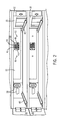
- FIG. 2 is a detailed perspective view of two compartments in the MCC enclosure of FIG. 1 designed to receive the reduced form factor component support;
- FIG. 3 is a diagrammatical representation of electrical connections made by a subplate and connector arrangement in the embodiment of FIGS. 1 and 2;
- FIG. 4 is a partial detailed view of certain connector configurations that may be used for interfacing the reduced form factor component support of the preceding figures with connectors provided on a subplate as illustrated in FIG. 3;
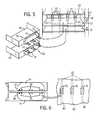
- FIG. 5 is a perspective view of an alternative arrangement for interfacing reduced form factor component supports with standard slots in an MCC enclosure.
- FIG. 6 is a somewhat detailed view of the arrangement of FIG. 5, illustrating a manner in which an invertible stab housing may be interfaced with standard slots in a bus support for an MCC in accordance with the embodiment of FIG. 5.
- a packaged electrical system 10 is illustrated generally as including an enclosure 12 in which a range of electrical and electronic components, switchgear, and so forth are housed.
- the system 10 may be configured as an MCC, such as for industrial control of motors and other loads.
- MCC motor control center
- the terms "motor control center” and "MCC” should include any suitable type of industrial, marine, commercial and other enclosure in which supports are provided for components in a compartmentalized fashion and interface with bus structures provided in the enclosure.
- the enclosure defines a shell 14 that encloses an internal volume 16 in which compartments 18 are subdivided. Each compartment typically has standard dimensions, particularly various standard heights.
- each compartment may be separated by shelves (shown partially broken away in FIG. 1 to show connections along the rear wall).
- a wireway may be provided in the enclosure, such as the vertical wireway shown to the right of the enclosure in FIG. 1.
- the enclosure 12 includes a series of power buses 22 (shown in dashed lines in FIG. 1) that route three phases of electrical power to the various compartments.
- the buses 22 are provided behind a bus cover 24 that limits access to the buses when energized.
- Slots 26 are provided in pairs, with a number of such rows of such slots being provided for plugging component supports into electrical contact with the buses.
- conventional component supports will include stabs that extend through the slots 26 to make contact with the buses 22.
- FIG. 1 The arrangement shown in FIG. 1 is particularly adapted for plug-in receipt of component supports by means of receptacles 28 for data and control power, and connectors 30 for line and load connections.
- power and data are provided to each component support at various levels. These levels may include low level power and data connections for the exchange of input and output data, monitoring and control instructions, and so forth via a known data exchange protocol, such as DeviceNet.
- power may be provided at a control power level, such as 24 vdc or 110 vac for operation of certain of the devices, such as relays and contactors.
- Such data and control power is provided in the enclosure of FIG. 1 via receptacles 28.
- the compartments illustrated in FIG. 1 are of a reduced form factor, as described in greater detail below, interfacing with the standard slot locations in the bus cover 24 is generally not feasible. That is, the reduced height form factor of the compartments results in locations for the connectors that are between conventional locations of the slots 26 in the bus cover.
- connectors 30 are provided on subplates 32 that are secured within the enclosure over the bus cover 24. Electrical connections are made on a rear side of the subplates 32 directly to the buses, and wiring then routes power to connectors 30.
- the connectors may be provided for both line connections (incoming power) and load connections (outgoing power) for each component support.
- the connectors may be configured for accommodating both three-wire three phase power and four-wire three phase power, with one receptacle being unwired when the connectors are used with three-wire three phase power.
- the compartments thus configured receive reduced form factor component supports as indicated at reference numeral 34.
- component supports are typically configured as slide-in units or drawers that support multiple components 36 that are wired together as subassemblies or sub-circuits.
- a mating connector 38 is provided on a rear wall of the component support 34.
- the connector 38 is designed to interface with connectors 30 within the compartment when the component support is slid into place.
- component support 34 has a 3.25 inch form factor.
- Such reduced form factor component supports are believed to be particularly useful for housing smaller components and circuits such as motor starters, motor controllers, and so forth.
- FIG. 2 illustrates, in somewhat greater detail, the arrangement of FIG. 1 for two reduced form factor compartments.
- slides 40 are provided within the enclosure for supporting the component support on a shelf that subdivides the enclosure into compartments.
- the subplate 32 then, is fixed (mechanically bolted or screwed) in place toward the rear of the compartment over the bus cover described above ( see, FIG. 1).
- the data and control power receptacles 28 are provided adjacent to the subplate 32.
- the subplate 32 includes line-side plugs 42 that are connected (stabbed or wired) to the buses routed in the rear of the enclosure ( see, FIG. 1) and provide for connections to the power source, typically the power grid.
- Load-side plugs 44 are provided and are routed to wiring that extends to the load, such as an electric motor or any other suitable load driven by the components within the compartment.
- an alignment pin 46 may be provided in the connector arrangement, along with an alignment receptacle 48. As described below, the pin 46 and receptacle 48 may interface with similar arrangements on the connector on the rear of the component support to ensure proper alignment of the connectors when the component support is slid into place and the connections made.
- alignment holes 50 may be provided in the subplate 32. These alignment holes are intended to receive pins, described below, that again facilitate the alignment of the component support with the subplate prior to making of the contacts between the connectors.
- FIG. 3 is a diagrammatical representation of the electrical connections made by the subplate 32 supporting the connectors 30.
- the line-side connector is electrically coupled to buses within the enclosure. Where a neutral bus is provided, this bus also may be connected to the connector via stabs or hard-wiring ( see, dashed lines in FIG. 3).
- the load-side connector 30 is wired to conductors for transmitting controlled output power to the load controlled by the components within the component support.
- Connector 30 is mechanically held by the subplate 32 which serves as a mechanical support and to facilitate alignment and plugging of the component support connector into connector 30.
- pins 52 extending from a rear surface of the component support 34 enter into alignment holes 50 in the subplate.
- the component support 34 is thus guided into place such that the mating connector 38 may make contact with the appropriate conductors of the connector 30 and supply power to the components 36 of the component support.
- FIG. 4 An exemplary arrangement for the foregoing connectors on the component support and subplate is illustrated in FIG. 4. To the left of the diagram in FIG. 4, the mating connector 38 on the rear of the component support 34 is illustrated. Load-side plugs 54 are provide in the connector for routing three phase power to a load. Similarly, line-side plugs 56 are provided for receiving three phase power from the buses of the enclosure. Neutral line-out 58 and line-in 60 connections are provided to accommodate neutral connections where four-wire three phase power is employed. On an opposite side of the connector, the connections illustrated in FIG. 4 are hard-wired to components within the component support 34.
- the connections on the subplate 32 are essentially the mirror image of those on the rear of the component support. That is, the connector 30 includes line-side plugs 62 that interface with the receptacles 56 on the component support. Similar load-side plugs 64 interface with the load-side receptacles 54 of the component support. Where four-wire three phase power is employed, neutral in 66 and neutral out 68 connections are provided. As will be appreciated by those skilled in the art, any suitable connectors may be used for the reduced form factor component supports provided herein. Moreover, the designations as "plug” and "receptacle” may be reversed where desired, with receptacles being provided in the connector of the subplate and plugs being provided on the component support.
- FIG. 5 illustrates an alternative configuration for a reduced form factor component support in accordance with the invention.
- the component supports 34 are made to interface directly with shared slots 70 in the enclosure 12. Slots 70 are essentially identical to slots 26 described above with reference to FIG. 1. However, slots 70 will be shared in the enclosure by the positioning of a divider or intermediate shelf 72 between the reduced form factor component supports 34.
- an invertible stab housing 74 is provided to facilitate contacting the bus bars 22 behind the bus cover 24, an invertible stab housing 74 is provided.
- stab housings are generally insulated enclosures that can be mounted on the rear of a component support and provide insulated hard-wired connections on the interior of the component support, with stabs 76 extending rearwardly from the stab housing.
- the stabs 76 are configured to enter through slots 70 and to make connections with bus bars 22 positioned behind the bus cover 24.
- the invertible stab housings 74 are designed such that stabs 76 are in close proximity to an edge of the housing. That is, when positioned in a first position as illustrated in upper component support 34 of FIG. 5, the stabs will exit near a lower edge of the component support, as indicated generally by reference numeral 78. In an inverted position, as indicated by reference numeral 80, the same housing can provide for stabs that exit near an upper edge of the component support. As the reduced from factor component supports are mounted in the enclosure, then, the stabs 76 of each stab housing will enter into engagement with bus bars 72 through shared slots 70 in the bus cover.
- the invertible stab housing 74 provides for stabs that can exit either near a lower edge of a component support or an upper edge of a component support, as indicated by reference numerals 78 and 80, respectively.
- the stabs 76 then, generally align with one another and are positioned sufficiently close to one another such that the stabs can enter into the shared slots 70 to complete connections with the buses 22 disposed behind the bus cover 24.
- a reduced form factor component support is provided for motor control centers and similar packaged electrical systems.
- the reduced form factor component support may be used with smaller components, such as small motor starters, motor drives, and so forth. Electrical connections with standard bus bars in the enclosure are made through special connectors mounted on subplates in the rear of the enclosure, or by an invertible stab housing that can allow the reduced form factor component support to share conventional slots in a bus cover, thereby providing access to the supply power in the enclosure.
Landscapes
- Engineering & Computer Science (AREA)
- Microelectronics & Electronic Packaging (AREA)
- Power Engineering (AREA)
- Connection Or Junction Boxes (AREA)
- Motor Or Generator Frames (AREA)
Applications Claiming Priority (1)
| Application Number | Priority Date | Filing Date | Title |
|---|---|---|---|
| US11/271,002 US7417848B2 (en) | 2005-11-11 | 2005-11-11 | Multiple height, high density horizontal low voltage motor control center |
Publications (2)
| Publication Number | Publication Date |
|---|---|
| EP1786070A1 true EP1786070A1 (de) | 2007-05-16 |
| EP1786070B1 EP1786070B1 (de) | 2008-08-20 |
Family
ID=37532995
Family Applications (1)
| Application Number | Title | Priority Date | Filing Date |
|---|---|---|---|
| EP06023380A Ceased EP1786070B1 (de) | 2005-11-11 | 2006-11-09 | Niederspannungs-Motorregelungseinheit hoher Dichte mit mehrfachen Höheneinstellungen |
Country Status (3)
| Country | Link |
|---|---|
| US (1) | US7417848B2 (de) |
| EP (1) | EP1786070B1 (de) |
| DE (1) | DE602006002341D1 (de) |
Cited By (3)
| Publication number | Priority date | Publication date | Assignee | Title |
|---|---|---|---|---|
| WO2008005485A3 (en) * | 2006-06-30 | 2008-03-20 | Siemens Energy & Automat | Electronic module and interlocking bus system including same |
| EP2388865A1 (de) * | 2010-05-18 | 2011-11-23 | Eaton Industries (Netherlands) B.V. | Verbindungsgruppe für Schaltschrank |
| CN113540896A (zh) * | 2021-07-22 | 2021-10-22 | 浙江杭可科技股份有限公司 | 一种高密度大电流驱动箱 |
Families Citing this family (20)
| Publication number | Priority date | Publication date | Assignee | Title |
|---|---|---|---|---|
| DE20303126U1 (de) * | 2003-02-25 | 2004-04-01 | Pfister Gmbh | Vorrichtung zur kontinuierlichen, gravimetrischen Dosierung |
| US7511946B2 (en) * | 2005-11-11 | 2009-03-31 | Rockwell Automation Technologies, Inc. | Vertical neutral bus and support for motor control center |
| EP1853098A3 (de) * | 2006-05-03 | 2013-07-10 | Parker-Hannifin Corporation | Modulares Stapelsystem und Verfahren mit Hochleistungsantrieb |
| US10973143B2 (en) | 2006-07-26 | 2021-04-06 | Eaton Intelligent Power Limited | Coordinating installation and connection of a motor control center subunit having moveable line contacts |
| US8817454B2 (en) | 2006-07-26 | 2014-08-26 | Eaton Corporation | Coordinating installation and connection of a motor control center subunit having moveable line contacts |
| US7688572B2 (en) | 2006-07-26 | 2010-03-30 | Eaton Corporation | Motor control center subunit having moveable line contacts and method of manufacture |
| TW200847901A (en) * | 2007-05-18 | 2008-12-01 | Cooler Master Co Ltd | Water-cooling heat-dissipation system |
| US7808775B2 (en) * | 2008-03-07 | 2010-10-05 | Deere & Company | Modular power distribution system having a sealing arrangement for use in a work machine |
| US8274782B2 (en) | 2010-09-30 | 2012-09-25 | Rockwell Automation Technologies, Inc. | Motor control center network connectivity method and system |
| US8952252B2 (en) | 2010-10-22 | 2015-02-10 | Rockwell Automation Technologies, Inc. | Arc resistant electrical enclosure |
| US9072191B2 (en) * | 2010-12-30 | 2015-06-30 | Schneider Electric It Corporation | Configurable rack and related methods |
| US9100208B2 (en) | 2011-09-27 | 2015-08-04 | Hubbell Incorporated | Method and apparatus for circuit emulation with integrated network diagnostics and reduced form factor in large public communication networks |
| US9595799B2 (en) | 2014-03-13 | 2017-03-14 | General Electric Company | Electrical enclosure having a dual bus bar and a component with a dual bus bar connector |
| US9337596B2 (en) * | 2014-07-14 | 2016-05-10 | Rockwell Automation Technologies, Inc. | Systems and methods for aligning a ground stab |
| DE102016221041A1 (de) * | 2016-10-26 | 2018-04-26 | Eaton Protection Systems Ip Gmbh & Co. Kg | Beheiztes elektrisches verteilersystem |
| WO2019192689A1 (en) * | 2018-04-04 | 2019-10-10 | Abb Schweiz Ag | Compartment for a withdrawable module |
| WO2019192690A1 (en) * | 2018-04-04 | 2019-10-10 | Abb Schweiz Ag | Arrangement comprising a compartment and a slide-in module |
| US10879658B2 (en) * | 2018-08-31 | 2020-12-29 | Hamilton Sundstrand Corporation | Load connectors for power panel assemblies |
| US20230132464A1 (en) * | 2021-10-28 | 2023-05-04 | Nuro, Inc. | Methods and apparatus for supporting compartment inserts with interface arrangements in autonomous delivery vehicles |
| CN220306716U (zh) * | 2023-07-26 | 2024-01-05 | 施耐德电气(中国)有限公司 | 用于开关柜的分线盒及开关柜 |
Citations (2)
| Publication number | Priority date | Publication date | Assignee | Title |
|---|---|---|---|---|
| US6414839B1 (en) * | 2000-09-29 | 2002-07-02 | Siemens Energy & Automation | Shutter mechanism for vertical bus of motor control center |
| EP1521511A2 (de) * | 2003-09-30 | 2005-04-06 | Rockwell Automation Technologies, Inc. | Verfahren und Gerät zur Verbindung einer Motorkontrollzentrale |
Family Cites Families (19)
| Publication number | Priority date | Publication date | Assignee | Title |
|---|---|---|---|---|
| US2725542A (en) * | 1953-07-20 | 1955-11-29 | Westinghouse Electric Corp | Bus duct structure and plug-in unit having polarizing means |
| US3096131A (en) * | 1961-01-03 | 1963-07-02 | Gen Electric | Electrical bus conductor |
| US3142003A (en) * | 1961-09-13 | 1964-07-21 | Gen Electric | Electrical control panel structure |
| US3113820A (en) * | 1961-10-16 | 1963-12-10 | Fed Pacific Electric Co | Insulated bus bar assembly |
| US3725746A (en) * | 1972-06-22 | 1973-04-03 | Allis Chalmers | Control center with expandable frame cabinet |
| AU501454B2 (en) * | 1974-07-12 | 1979-06-21 | Westinghouse Electric Corporation | Panel board & circuit breaker system |
| GB1477812A (en) * | 1974-07-22 | 1977-06-29 | Square D Co | Stab connector for vertical bus bar plug-on unit |
| US4305114A (en) * | 1979-06-19 | 1981-12-08 | Tokyo Shibaura Denki Kabushiki Kaisha | Motor control center |
| JPS5936483B2 (ja) * | 1979-06-22 | 1984-09-04 | 株式会社東芝 | 母線装置 |
| US4789344A (en) * | 1987-06-26 | 1988-12-06 | Eaton Corporation | Plug-in connector module for a removable control unit of a motor control center |
| US5642256A (en) * | 1994-08-05 | 1997-06-24 | Square D Company | Interlock mechanism for a motor control unit |
| US5510960A (en) * | 1994-08-05 | 1996-04-23 | Square D Company | Connector assembly for a motor control unit |
| US5486663A (en) * | 1994-10-19 | 1996-01-23 | Eaton Corporation | Motor control center removable control unit interlock |
| US5938744A (en) * | 1997-11-04 | 1999-08-17 | Aiwa/Raid Technlogy, | Method for managing multiple DMA queues by a single controller |
| US6273750B1 (en) * | 1999-09-28 | 2001-08-14 | Rockwell Technologies, Llc | Connector and cable system for panel-mounted circuitry |
| US6280216B1 (en) * | 1999-11-09 | 2001-08-28 | General Electric Company | Lug adapter assembly having reduced force clips |
| US6531670B1 (en) * | 2000-10-26 | 2003-03-11 | Square D Company | Motor control center relay reset mechanism |
| US6657150B1 (en) * | 2002-06-14 | 2003-12-02 | Eaton Corporation | Shorting switch and system to eliminate arcing faults in power distribution equipment |
| US8908335B2 (en) * | 2004-09-30 | 2014-12-09 | Rockwell Automation Technologies, Inc. | Arc extinguishing stab housing and method |
-
2005
- 2005-11-11 US US11/271,002 patent/US7417848B2/en not_active Expired - Lifetime
-
2006
- 2006-11-09 EP EP06023380A patent/EP1786070B1/de not_active Ceased
- 2006-11-09 DE DE602006002341T patent/DE602006002341D1/de active Active
Patent Citations (2)
| Publication number | Priority date | Publication date | Assignee | Title |
|---|---|---|---|---|
| US6414839B1 (en) * | 2000-09-29 | 2002-07-02 | Siemens Energy & Automation | Shutter mechanism for vertical bus of motor control center |
| EP1521511A2 (de) * | 2003-09-30 | 2005-04-06 | Rockwell Automation Technologies, Inc. | Verfahren und Gerät zur Verbindung einer Motorkontrollzentrale |
Cited By (5)
| Publication number | Priority date | Publication date | Assignee | Title |
|---|---|---|---|---|
| WO2008005485A3 (en) * | 2006-06-30 | 2008-03-20 | Siemens Energy & Automat | Electronic module and interlocking bus system including same |
| US8018735B2 (en) | 2006-06-30 | 2011-09-13 | Siemens Industry, Inc. | Electronic module and interlocking bus system including same |
| EP2388865A1 (de) * | 2010-05-18 | 2011-11-23 | Eaton Industries (Netherlands) B.V. | Verbindungsgruppe für Schaltschrank |
| CN113540896A (zh) * | 2021-07-22 | 2021-10-22 | 浙江杭可科技股份有限公司 | 一种高密度大电流驱动箱 |
| CN113540896B (zh) * | 2021-07-22 | 2024-05-10 | 浙江杭可科技股份有限公司 | 一种高密度大电流驱动箱 |
Also Published As
| Publication number | Publication date |
|---|---|
| US20070109731A1 (en) | 2007-05-17 |
| DE602006002341D1 (de) | 2008-10-02 |
| EP1786070B1 (de) | 2008-08-20 |
| US7417848B2 (en) | 2008-08-26 |
Similar Documents
| Publication | Publication Date | Title |
|---|---|---|
| US7417848B2 (en) | Multiple height, high density horizontal low voltage motor control center | |
| EP1786076B1 (de) | Bus- und Signalkabelkanal für MCC-Verteiler | |
| US8553395B2 (en) | Motor control center network connectivity method and system | |
| US7419394B2 (en) | Electrical system having withdrawable unit with maintained control and communication connection | |
| US3394287A (en) | Frames for electrical communication apparatus | |
| EP2926356B1 (de) | Schaltvorrichtung mit mehreren verbindungszonen | |
| EP1952496B1 (de) | Busbar-unterstützungsstruktur für eine motorsteuerzentrale | |
| US9515463B2 (en) | Systems and methods for a fused motor load ground | |
| US20080055822A1 (en) | Scalable plant with top or bottom entry flexibility | |
| CN108879540B (zh) | 配电系统和组装配电系统的方法 | |
| CA2600553A1 (en) | Module rear wall for a switchgear assembly module, switchgear assembly module and electrical switchgear assembly | |
| US9692213B2 (en) | Doorless modular panelboard | |
| JP3113266U (ja) | ユニット式分電盤 | |
| JP4958282B2 (ja) | ブレーカユニット | |
| KR100797159B1 (ko) | 제어반의 리셉터클 커넥터 설치구조 | |
| US11996678B2 (en) | Switching and/or distributing device | |
| JP2009189128A (ja) | 制御盤 | |
| CN211790039U (zh) | 开关柜 | |
| JP2001157318A (ja) | 特高金属閉鎖形スイッチギヤ | |
| JP6515832B2 (ja) | 配電盤、母線 | |
| JP2001309508A (ja) | 配電盤 | |
| KR100359844B1 (ko) | 모터 제어 센터 | |
| JP2007300706A (ja) | 分電盤 | |
| JPS62203505A (ja) | コントロ−ルセンタ | |
| JP2001352617A (ja) | 船舶の発電機用配電盤 |
Legal Events
| Date | Code | Title | Description |
|---|---|---|---|
| PUAI | Public reference made under article 153(3) epc to a published international application that has entered the european phase |
Free format text: ORIGINAL CODE: 0009012 |
|
| AK | Designated contracting states |
Kind code of ref document: A1 Designated state(s): AT BE BG CH CY CZ DE DK EE ES FI FR GB GR HU IE IS IT LI LT LU LV MC NL PL PT RO SE SI SK TR |
|
| AX | Request for extension of the european patent |
Extension state: AL BA HR MK YU |
|
| 17P | Request for examination filed |
Effective date: 20070821 |
|
| 17Q | First examination report despatched |
Effective date: 20070919 |
|
| AKX | Designation fees paid |
Designated state(s): DE FR GB IT |
|
| GRAP | Despatch of communication of intention to grant a patent |
Free format text: ORIGINAL CODE: EPIDOSNIGR1 |
|
| GRAS | Grant fee paid |
Free format text: ORIGINAL CODE: EPIDOSNIGR3 |
|
| GRAA | (expected) grant |
Free format text: ORIGINAL CODE: 0009210 |
|
| AK | Designated contracting states |
Kind code of ref document: B1 Designated state(s): DE FR GB IT |
|
| REG | Reference to a national code |
Ref country code: GB Ref legal event code: FG4D |
|
| REF | Corresponds to: |
Ref document number: 602006002341 Country of ref document: DE Date of ref document: 20081002 Kind code of ref document: P |
|
| PLBE | No opposition filed within time limit |
Free format text: ORIGINAL CODE: 0009261 |
|
| STAA | Information on the status of an ep patent application or granted ep patent |
Free format text: STATUS: NO OPPOSITION FILED WITHIN TIME LIMIT |
|
| 26N | No opposition filed |
Effective date: 20090525 |
|
| REG | Reference to a national code |
Ref country code: FR Ref legal event code: PLFP Year of fee payment: 10 |
|
| REG | Reference to a national code |
Ref country code: FR Ref legal event code: PLFP Year of fee payment: 11 |
|
| REG | Reference to a national code |
Ref country code: FR Ref legal event code: PLFP Year of fee payment: 12 |
|
| P01 | Opt-out of the competence of the unified patent court (upc) registered |
Effective date: 20230404 |
|
| PGFP | Annual fee paid to national office [announced via postgrant information from national office to epo] |
Ref country code: GB Payment date: 20231019 Year of fee payment: 18 |
|
| PGFP | Annual fee paid to national office [announced via postgrant information from national office to epo] |
Ref country code: IT Payment date: 20231019 Year of fee payment: 18 Ref country code: FR Payment date: 20231019 Year of fee payment: 18 Ref country code: DE Payment date: 20231019 Year of fee payment: 18 |
|
| REG | Reference to a national code |
Ref country code: DE Ref legal event code: R119 Ref document number: 602006002341 Country of ref document: DE |
|
| GBPC | Gb: european patent ceased through non-payment of renewal fee |
Effective date: 20241109 |
|
| PG25 | Lapsed in a contracting state [announced via postgrant information from national office to epo] |
Ref country code: DE Free format text: LAPSE BECAUSE OF NON-PAYMENT OF DUE FEES Effective date: 20250603 |
|
| PG25 | Lapsed in a contracting state [announced via postgrant information from national office to epo] |
Ref country code: IT Free format text: LAPSE BECAUSE OF NON-PAYMENT OF DUE FEES Effective date: 20241109 |
|
| PG25 | Lapsed in a contracting state [announced via postgrant information from national office to epo] |
Ref country code: GB Free format text: LAPSE BECAUSE OF NON-PAYMENT OF DUE FEES Effective date: 20241109 |
|
| PG25 | Lapsed in a contracting state [announced via postgrant information from national office to epo] |
Ref country code: FR Free format text: LAPSE BECAUSE OF NON-PAYMENT OF DUE FEES Effective date: 20241130 |