EP1786072B1 - Dispositif de traitement de câble et méthode d'utilisation - Google Patents
Dispositif de traitement de câble et méthode d'utilisation Download PDFInfo
- Publication number
- EP1786072B1 EP1786072B1 EP20060123383 EP06123383A EP1786072B1 EP 1786072 B1 EP1786072 B1 EP 1786072B1 EP 20060123383 EP20060123383 EP 20060123383 EP 06123383 A EP06123383 A EP 06123383A EP 1786072 B1 EP1786072 B1 EP 1786072B1
- Authority
- EP
- European Patent Office
- Prior art keywords
- wire
- gripper
- cable
- pull
- force
- Prior art date
- Legal status (The legal status is an assumption and is not a legal conclusion. Google has not performed a legal analysis and makes no representation as to the accuracy of the status listed.)
- Active
Links
Images



Classifications
-
- H—ELECTRICITY
- H01—ELECTRIC ELEMENTS
- H01R—ELECTRICALLY-CONDUCTIVE CONNECTIONS; STRUCTURAL ASSOCIATIONS OF A PLURALITY OF MUTUALLY-INSULATED ELECTRICAL CONNECTING ELEMENTS; COUPLING DEVICES; CURRENT COLLECTORS
- H01R43/00—Apparatus or processes specially adapted for manufacturing, assembling, maintaining, or repairing of line connectors or current collectors or for joining electric conductors
- H01R43/04—Apparatus or processes specially adapted for manufacturing, assembling, maintaining, or repairing of line connectors or current collectors or for joining electric conductors for forming connections by deformation, e.g. crimping tool
- H01R43/048—Crimping apparatus or processes
- H01R43/0486—Crimping apparatus or processes with force measuring means
-
- H—ELECTRICITY
- H01—ELECTRIC ELEMENTS
- H01R—ELECTRICALLY-CONDUCTIVE CONNECTIONS; STRUCTURAL ASSOCIATIONS OF A PLURALITY OF MUTUALLY-INSULATED ELECTRICAL CONNECTING ELEMENTS; COUPLING DEVICES; CURRENT COLLECTORS
- H01R43/00—Apparatus or processes specially adapted for manufacturing, assembling, maintaining, or repairing of line connectors or current collectors or for joining electric conductors
- H01R43/04—Apparatus or processes specially adapted for manufacturing, assembling, maintaining, or repairing of line connectors or current collectors or for joining electric conductors for forming connections by deformation, e.g. crimping tool
- H01R43/048—Crimping apparatus or processes
-
- H—ELECTRICITY
- H01—ELECTRIC ELEMENTS
- H01R—ELECTRICALLY-CONDUCTIVE CONNECTIONS; STRUCTURAL ASSOCIATIONS OF A PLURALITY OF MUTUALLY-INSULATED ELECTRICAL CONNECTING ELEMENTS; COUPLING DEVICES; CURRENT COLLECTORS
- H01R43/00—Apparatus or processes specially adapted for manufacturing, assembling, maintaining, or repairing of line connectors or current collectors or for joining electric conductors
- H01R43/04—Apparatus or processes specially adapted for manufacturing, assembling, maintaining, or repairing of line connectors or current collectors or for joining electric conductors for forming connections by deformation, e.g. crimping tool
- H01R43/048—Crimping apparatus or processes
- H01R43/052—Crimping apparatus or processes with wire-feeding mechanism
Definitions
- the invention relates to a cable processing device having processing stations for assembling a cable and method for operating such a cable processing device, wherein at least one gripper feeds the cable to the processing stations for producing a cable end connection and is suitable for testing the cable end connection produced by the processing stations.
- Known means for testing a crimped connection consist of a holding device for holding the crimp contact and of a pulling device for acting on the conductor crimp with a cable longitudinal axis acting force.
- the insulation crimp can be removed manually before the crimping process, so that the pull-out force for the conductor crimp is not falsified. With insulation crimp, the pull-out force for the conductor crimp is increased by two to five percent.
- the testing device can be operated manually or by motor, wherein the measured by means of force sensors traction is displayed. If the crimped connection does not or only partially withstands a predetermined pull-out force, the cable is manually removed.
- a cable processing machine has become known in which a tape drive feeds a cable to a first pivoting arm with a first gripper.
- the first pivot arm is set in a pivoting movement and / or in a linear movement.
- a second pivot arm is set in a pivoting movement and / or in a linear movement.
- a holding device serves to test the cable end connection or crimp connection produced in the automated cable processing process, the linear movement of the gripper also being used for the automated testing of the cable end connection.
- a disadvantage of the known device is that the gripper closing force for cables with medium and large cross sections for the Auszugkraftmaschine is not sufficient. When the pull-out movement is carried out by the gripper, the gripper can not hold or clamp the cable sufficiently. If the cable slips in the gripper, the desired pull-out force can not be achieved. A much more built gripper could meet these requirements, but at the expense of the gripper dimensions and at the expense of moving gripper mass and the associated larger drive.
- the invention aims to remedy this situation.
- the invention as characterized in the independent claims solves the problem of avoiding the disadvantages of the known device and to provide a cable processing device and a method for the operation of such a cable processing device, by means of the examination of a cable end connection within an automated cable processing process for medium and large cable is feasible.
- this cable processing device with processing stations for assembling a cable, at least one gripper is provided, which supplies the cable to the processing stations for producing a cable end connection and is suitable for testing the cable end connection produced by the processing stations, wherein an extension device is provided with at least one holding unit and a clamping unit and wherein the gripper supplies the cable end connection to the holding unit for holding and feeds the cable to the clamping unit for clamping and acts on the clamping unit with a pull-out force in the cable longitudinal axis.
- the cable is fed by at least one gripper to the processing stations, the gripper being used for testing the cable end connection made by the processing stations, the cable being received from the gripper of an extension device comprising at least one gripper Holding unit and a clamping unit is supplied and the gripper is applied to the clamping unit with the necessary for the test pull-out force, the detained by means of the holding unit Jardinenditati counteracts the pull-out force.
- the examination of the cable end connection by means of a pull-out force measurement is carried out especially when setting up the cable processing machine, if necessary also occasionally during production. Since the clamping forces that can be generated by means of the grippers or gripper jaws are sufficient for all other cable processing processes, it is advantageous to provide an additional clamping unit capable of holding small, medium and large cables in the case of the pull-out force measurement.
- the pull-out movement or the generation of the pull-out force continues to take place by means of the gripper arm drive.
- the pull-out force can be measured via the flow of the gripper arm drive.
- the influence of the insulation crimp on the pull-out force of the conductor crimp can be kept negligibly small by cutting the insulation behind the crimp contact by means of the stripping knives.
- existing modules of the cable processing device can be used for testing the cable end connection produced in the automated cable processing process.
- grippers arranged on pivoting arms or grippers arranged on transfer devices are used to feed the cable to the processing stations.
- the gripper is moved not only in the circle or in the transfer direction but also linearly in the swivel arm longitudinal axis or transversely to the transfer direction.
- the linear movement or transverse movement of the gripper which extends horizontally into the depth of the cable processing device, is necessary, for example, for feeding cables to different crimp contacts or for feeding cables with grommets or for supplying cables to recessed processing stations.
- the linear motion of the gripper is used not only to feed the cable to the processing stations, but also to automatically test the cable end connection.
- the cable end connection or the crimp contact is fed to a holding unit and held by this.
- the gripper places the cable in a clamping unit that clamps the cable.
- the gripper acts on the clamping unit with a pull-out force in the cable longitudinal axis by means of a linear movement away from the holding unit.
- the cable processing device can be constructed simpler and operate more productive and better quality.
- the gripper and clamping unit allow a pull-out force measurement even for medium and large cables, without having to build the gripper stronger or change its mass or gripper arm drive.
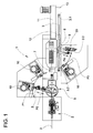
- Fig. 1 shows a cable processing machine 1 with a designed as a tape drive 2 cable feed device, wherein the tape drive 2, a cable 3 a first pivot arm 4 with a first gripper 5 supplies.
- first drives 6 By means of first drives 6, the first pivot arm 4 can be placed in a pivoting movement symbolized by an arrow P1 and / or in a linear movement symbolized by an arrow P2.
- separation / stripping knives 7 With separation / stripping knives 7, the cable can be separated and / or stripped.
- the cable sheath or the cable insulation is cut by means of the stripping blades and the insulation residue is removed by means of a pull-off movement.
- an additional cut is made on the cable sheath by means of the stripping knives, the insulation crimp produced during the crimping process comprising the additional insulation residue.
- the additional insulation residue covered by the insulation crimp slides on the cable ladder.
- the cable processing machine 1 has a second pivot arm 8 with a second gripper 9.
- the second pivot arm 8 can be placed in a symbolized by an arrow P3 pivoting movement and / or in a symbolized by an arrow P4 linear motion.
- the first pivot arm 4 serves as a feeder by means of rotary motion P1 and linear movement P2 side of the cable longitudinal axis arranged processing stations 10 (for example, crimping presses and / or Tüllenbe publisheder) with leading cable ends 3.1.
- the second pivot arm 8 which is set in motion by means of second drives 12, serves processing stations 10 (for example crimping presses and / or grommets) arranged laterally with the cable ends 3.2 as feed devices by means of rotational movement P3 and linear movement P4 laterally of the cable longitudinal axis.
- processing stations 10 for example crimping presses and / or grommets
- the cable 3 is transported by means of a conveyor belt 11.
- the second gripper 9 summarizes the trailing cable end 3.2, then the cable 3 is separated and the trailing cable end 3.2 stripped and fed to the processing stations 10. After processing the trailing end of the cable 3.2, the cable 3 enters a tray thirteenth
- Denoted at 20 is an extension device which serves to test the cable end connection 15 produced in the automated cable processing process, referred to below as the crimp contact 15.
- a conductor crimp 15.1 comprises a cable conductor and an insulation crimp 15.2 comprises the cable insulation, wherein, as in Fig. 3 shown, even a grommet 15.3 be placed on the cable insulation can.
- the testing of other cable end connections such as solder joints are also possible.
- the extension device 20 is arranged in the pivoting range of the second gripper 9. If not both crimp contacts must be checked, the extension device 20 may also be arranged in the pivoting range of the first gripper 5.
- the cable end 3.1.3.2 with crimp contact 15 is fed by means of gripper 9 of the extension device 20, wherein the crimp contact 15 is held by means of a holding unit 21,22 and the cable end is clamped 3.1.3.2 by means of a clamping unit 23.
- the gripper 9 pushes in the direction of the cable longitudinal axis against the clamping unit 23 and acts on the cable 3 with an extracting force AK in the cable longitudinal axis by means of a linear movement P4 away from the crimp contact 15.
- the force exerted on the cable 3 pull-out force AK is for example by means of at least one of the holding unit 21st 22 arranged force sensor or by means of the motor current of the linear motion P4 generating motor measured.
- the control of the cable processing device specifies the pull-out force and detects the measured pull-out force AK, for example, for statistical or control purposes.
- the cable 3 with crimp contact 15 zuibide gripper 9 performs with limited current from a linear motion P4.
- the current limit corresponds to the pull-out force AK. Failure to reach the pull-out force AK or the current limit means that the crimp connection has not withstood the required pull-out force AK, the wire crimp 15.1 is faulty. If the pull-out force is measured by means of force sensors, the motor current of the motor generating the linear movement P4 is increased until the required pull-out force is reached. Failure to reach the required and measured by the force sensors pull-out force AK means that the Crimp connection of the required pull-out force AK has not withstood, the wire crimp 15.1 is faulty.
- Fig. 2 shows details of the extension means 20 with the first holding unit 21, the second holding unit 22 and the clamping unit 23.
- a housing 24 serves as a support for the holding units 21,22 and the clamping unit 23.
- the first holding unit 21 is for checking the crimp connection of the trailing end of the cable 3.2 provided and has a first cutting edge 25 and a second cutting edge 26, wherein the first cutting edge 25 is movable in the direction symbolized by an arrow P5.
- the second cutting edge 26 can also be designed deliverable.
- the blades 25, 26 hold the crimp contact of the trailing cable end 3.2.
- the second holding unit 22 is provided for the pull-out force measurement of the crimped connection of the leading cable end 3.1 and has a first cutting edge 27 and a second cutting edge 28, wherein the first cutting edge 27 is movable in the direction symbolized by an arrow P6. During the pull-out force measurement, the cutting edges 27, 28 hold the crimp contact of the leading cable end 3.1.
- the clamping unit 23 is freely movable relative to the housing 24 in the direction symbolized by an arrow P7 and has a first clamping element 29 and a second clamping element 30 by means of which the cable end 3.1.3.2 can be clamped.
- the clamping elements 29,30 may have different clamping surfaces. (Wavy surface, V-shaped surface, flat surface, fluted surface, ect.).
- the first clamping element 29 is movable by means of an actuator 31 (for example by means of a pneumatic cylinder) in the direction symbolized by an arrow P8.
- the second clamping element 30 can also be deliverable. During the test, the clamping elements 29,30 clamp the cable end 3.1.3.2 firmly.
- clamping unit 23 In one or the other end position of the clamping unit 23 dip bolts 32 in holes 33 of the housing 24 a. In the holes 33 magnets are arranged, which hold the bolts 32 and the clamping unit 23 in the respective end position. The end positions are monitored by sensors.
- a docking finger 34 arranged on the clamping unit 23 serves to dock the gripper 9 to the clamping unit 23.
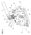
- Fig. 3 shows the gripper 9 with a trailing end of the cable 3.2 when docking with the clamping unit 23.
- the gripper 9 knows the end position of the clamping unit 23 and docks on the docking finger 34 with a rotational movement P3.
- the gripper 9 moves the clamping unit 23 from the end position into an intermediate position, in which the gripper 9 can place the crimp contact 15 in the first holding unit 21 and the trailing cable end 3.2 between the clamping elements 29, 30 of the clamping unit 23.
- the gripper 9 docks with a rotational movement P3 from the dock finger 34 and moves with a linear movement P4 in the direction of cutting 25,26 of the first holding unit 21st
- Fig. 4 shows the gripper 9 when inserting the crimp contact 15 in the first holding unit 21 and when inserting the trailing cable end 3.2 in the clamping unit 23.
- the gripper 9 performs a rotational movement P3 until the crimp contact 15 between the cutting 25,26 and the trailing cable end is 3.2 between the clamping elements 29,30.
- Fig. 5 shows the inserted, trailing cable end 3.2 and the inserted crimp contact 15.
- the first clamping element 29 of the clamping unit 23 has been delivered with the linear movement P8 and clamps together with the second clamping element 30, the trailing end of the cable 3.2.
- the first cutting edge 25 of the first holding unit 21 has been delivered with the linear movement P5 and holds together with the second cutting edge 26 the crimp contact 15.
- the gripper 9 or the gripper jaws 9.1 are opened. Between the gripper 9 and the clamping unit 23 is still a small distance AB.
- Fig. 6 shows the extract process.
- the gripper 9 acts on the clamping unit 23 with a pull-out force AK in the cable longitudinal axis by means of a linear movement away from the first holding unit 21.
- the gripper 9 pushes in the direction of the cable longitudinal axis against the clamping unit 23 and acts on the cable 3 with the pull-out force AK in the cable longitudinal axis by means of a Linear movement P4 away from the crimp contact 15.
- the pull-out force AK exerted on the cable 3 is measured, for example, by means of at least one force sensor arranged on the holding unit 21, 22 or by means of the motor current of the motor producing the linear movement P4.
- the cable 3 which is no longer usable is picked up again by the gripper 9 and removed.
- Fig. 7 shows a variant of the extension device 20.
- the housing 24 of the extension device 20 is disposed on a linear slide 20.1, which is acted upon by means of a force acting in the direction of the cable longitudinal axis force F (for example by means of a pneumatic actuator).
- a force acting in the direction of the cable longitudinal axis force F for example by means of a pneumatic actuator.
- the controller of the linear motion P4 generating drive remains switched on and controls standstill position in the position shown, the gripper 9 in the direction of the cable longitudinal axis abuts against the clamping unit 23.
- the applied force F of the gripper 9 remains in the standstill position and it must take the reaction force of the force F, which can be determined by means of current measurement on the linear motion P4 generating drive.
- Insertion and pullout test for the leading end of cable 3.1 is analogous to the insertion and analog to the pull-out of the trailing cable end 3.2 with the difference that the leading cable end 3.1 gripper arm side, the crimp 15 is inserted into the second holder 22 and the gripper 9 during the extraction process, the clamping unit 23 pushes.
- the pull-out force measurement can be carried out successively on both crimp contacts in a time-saving manner. Thus, only one cable is rejected.
- the clamping unit 23 can also be used for movement in the be symbolized by arrow P7 direction provided with its own drive.
- the gripper 9 generates no extraction force.
- the device according to the invention for pull-out force measurement can be used not only with the swivel arms set out above.
- the device according to the invention for pull-out force measurement can also be used, for example, in devices for the linear supply of cable ends, for example in the US Pat EP 1 073 163 B1 disclosed.
- other movement sequences for the delivery of the cable to be measured to Auszugeinrichraum 20 may be provided.
Landscapes
- Engineering & Computer Science (AREA)
- Manufacturing & Machinery (AREA)
- Manufacturing Of Electrical Connectors (AREA)
Claims (10)
- Dispositif de traitement de câble (1) comportant des stations de traitement (7, 10) pour la préparation d'un câble (3), avec lequel au moins un élément de préhension (5, 9) amène le câble (3) dans les stations de traitement (7, 10) en vue de réaliser une connexion d'extrémité de câble (15) et est apte à être utilisé pour tester ladite connexion (15) réalisée par les stations de traitement (7, 10),
caractérisé en ce qu'il est prévu un dispositif d'arrachement (20) avec au moins une unité de retenue (21) et une unité de serrage (23), l'élément de préhension (5, 9) amenant la connexion d'extrémité de câble (15) dans l'unité de retenue (21) pour l'immobiliser, et le câble (3) dans l'unité de serrage (23) pour le bloquer, et contraignant l'unité de serrage (23) avec une force d'arrachement (AK) dans le sens de l'axe longitudinal du câble. - Dispositif de traitement de câble selon la revendication 1, caractérisé en ce que l'unité de serrage (23) est librement mobile dans l'axe longitudinal du câble.
- Dispositif de traitement de câble selon la revendication 1, caractérisé en ce que le carter (24) du dispositif d'arrachement (20) est disposé sur un chariot linéaire (20.1) qui est apte à être contraint à l'aide d'une force (F) agissant dans le sens de l'axe longitudinal du câble, l'élément de préhension (9) restant dans la position d'arrêt et recevant la force de réaction de la force (F).
- Dispositif de traitement de câble selon la revendication 2 ou 3, caractérisé en ce que l'unité de serrage (23) comporte des éléments de serrage (29, 30) pour bloquer le câble (3), au moins un élément de serrage (29) étant apte à être avancé.
- Dispositif de traitement de câble selon l'une des revendications 1 à 4, caractérisé en ce que l'unité de retenue (21) comporte des lames (25, 26) pour immobiliser le contact (15) de la connexion d'extrémité de câble, au moins une lame (25, 26) étant apte à être avancée.
- Procédé pour faire fonctionner un dispositif de traitement de câble (1) comportant des stations de traitement (7, 10) pour la préparation d'un câble (3), selon lequel le câble (3) est amené par au moins un élément de préhension (5, 9) dans les stations de traitement (7, 10), et l'élément de préhension (5, 9) est utilisé pour tester la connexion d'extrémité de câble (15) réalisée par les stations de traitement (7, 10),
caractérisé en ce que le câble (3) est amené par l'élément de préhension (5, 9) dans un dispositif d'arrachement (20) comprenant au moins une unité de retenue (21) et une unité de serrage (23), et l'élément de préhension (5, 9) contraint l'unité de serrage (23) avec la force d'arrachement (AK) nécessaire pour le test, la connexion d'extrémité de câble (15) immobilisée à l'aide de l'unité de retenue (21) agissant à l'encontre de la force d'arrachement (AK). - Procédé selon la revendication 6, caractérisé en ce qu'un contact de la connexion d'extrémité de câble (15) est amené par l'élément de préhension (5, 9) dans l'unité de retenue (21), en ce que le contact est immobilisé par l'unité de retenue (21), le câble (3) est amené par l'élément de préhension (5, 9) dans l'unité de serrage (23) et le câble (3) est bloqué par l'unité de serrage (23).
- Procédé selon la revendication 6 ou 7, caractérisé en ce qu'une force d'arrachement (AK) est mesurée à l'aide d'au moins un capteur de force.
- Procédé selon la revendication 6 ou 7,
caractérisé en ce qu'une force d'arrachement (AK) est définie à l'aide d'un courant du moteur qui génère le mouvement linéaire de l'élément de préhension (5, 9). - Procédé selon l'une des revendications 6 à 9, caractérisé en ce que pour un câble (3) prévu pour la mesure de force d'arrachement, une entaille supplémentaire est réalisée à l'aide de lames de dénudage (7) sur la gaine du câble, l'élément de sertissage isolant (15.2) réalisé lors de l'opération de sertissage entourant le reste d'isolation supplémentaire.
Priority Applications (1)
| Application Number | Priority Date | Filing Date | Title |
|---|---|---|---|
| EP20060123383 EP1786072B1 (fr) | 2005-11-10 | 2006-11-02 | Dispositif de traitement de câble et méthode d'utilisation |
Applications Claiming Priority (2)
| Application Number | Priority Date | Filing Date | Title |
|---|---|---|---|
| EP05110576 | 2005-11-10 | ||
| EP20060123383 EP1786072B1 (fr) | 2005-11-10 | 2006-11-02 | Dispositif de traitement de câble et méthode d'utilisation |
Publications (2)
| Publication Number | Publication Date |
|---|---|
| EP1786072A1 EP1786072A1 (fr) | 2007-05-16 |
| EP1786072B1 true EP1786072B1 (fr) | 2008-07-16 |
Family
ID=37945962
Family Applications (1)
| Application Number | Title | Priority Date | Filing Date |
|---|---|---|---|
| EP20060123383 Active EP1786072B1 (fr) | 2005-11-10 | 2006-11-02 | Dispositif de traitement de câble et méthode d'utilisation |
Country Status (1)
| Country | Link |
|---|---|
| EP (1) | EP1786072B1 (fr) |
Cited By (2)
| Publication number | Priority date | Publication date | Assignee | Title |
|---|---|---|---|---|
| EP3155700B1 (fr) | 2014-06-16 | 2018-07-11 | Delphi Technologies, Inc. | Procédé et dispositif d'assemblage d'un boîtier de connexion |
| EP3875934B1 (fr) * | 2020-03-03 | 2024-04-10 | Komax SLE GmbH & Co. KG | Dispositif de mesure de la force d'arrachage |
Families Citing this family (6)
| Publication number | Priority date | Publication date | Assignee | Title |
|---|---|---|---|---|
| DE102007018555B4 (de) * | 2007-04-18 | 2009-02-19 | Schäfer Werkzeug- und Sondermaschinenbau GmbH | Kabelbearbeitungseinrichtung |
| EP2937953B1 (fr) | 2014-04-25 | 2017-06-21 | Komax Holding AG | Procédé et dispositif de fabrication d'une connexion par sertissage |
| US11069462B2 (en) | 2016-12-15 | 2021-07-20 | The Boeing Company | Automated wire processing system and methods |
| EP3402020B1 (fr) * | 2017-05-09 | 2021-07-07 | Schleuniger AG | Machine d'usinage de câble et procédé destiné à tronçonner un câble |
| US20210075177A1 (en) * | 2018-04-24 | 2021-03-11 | Schleuniger Ag | Tool changer, machine tool, and method for changing a tool |
| CN113311302B (zh) * | 2021-06-16 | 2023-11-03 | 晶锋集团股份有限公司 | 一种检测电缆绝缘性的高效半自动装置 |
Family Cites Families (1)
| Publication number | Priority date | Publication date | Assignee | Title |
|---|---|---|---|---|
| EP1515403B1 (fr) * | 2003-09-10 | 2007-10-24 | komax Holding AG | Dispositif de traitement de câble |
-
2006
- 2006-11-02 EP EP20060123383 patent/EP1786072B1/fr active Active
Cited By (2)
| Publication number | Priority date | Publication date | Assignee | Title |
|---|---|---|---|---|
| EP3155700B1 (fr) | 2014-06-16 | 2018-07-11 | Delphi Technologies, Inc. | Procédé et dispositif d'assemblage d'un boîtier de connexion |
| EP3875934B1 (fr) * | 2020-03-03 | 2024-04-10 | Komax SLE GmbH & Co. KG | Dispositif de mesure de la force d'arrachage |
Also Published As
| Publication number | Publication date |
|---|---|
| EP1786072A1 (fr) | 2007-05-16 |
Similar Documents
| Publication | Publication Date | Title |
|---|---|---|
| EP1515403B1 (fr) | Dispositif de traitement de câble | |
| EP3949035B1 (fr) | Dispositif et procédé de montage d'un connecteur électrique enfichable | |
| EP0348615B1 (fr) | Procédé de montage automatique de conducteurs électriques avec des pièces de contact dans des boîtiers de connecteurs | |
| DE69300906T2 (de) | Mechanismus für das Einfügen verdrahteter Klemmen in dem Verbindergehäuse. | |
| EP0440955B1 (fr) | Dispositif pour le montage automatique de câbles électriques avec pièces de connexion dans des boîtiers de prise | |
| DE69223357T2 (de) | Vorrichtung und Verfahren zum Verbinden von elektrischen Kabelbäumen | |
| DE19811623C2 (de) | Pressschweißvorrichtung zum Verdrahten und Verfahren zum Herstellen eines Kabelbaumes | |
| DE102007045279B4 (de) | Vorrichtung und Verfahren zur Herstellung von Kabelbäumen | |
| WO2018189103A1 (fr) | Tête d'usinage ainsi qu'installation et procédé servant à équiper de manière automatisée des boîtiers de connecteur enfichable en éléments conducteurs | |
| DE102015102060A1 (de) | Crimpmaschine | |
| EP3717182A1 (fr) | Procédé pour le câblage électrique par une séquence de câbles de composants électroniques dans la construction d'installations de commutation et dispositif robotique correspondant | |
| EP3841856A1 (fr) | Robot de câblage et procédé de câblage, système et procédé permettant de planifier des câblages, système et procédé de détection de composants | |
| DE102010017981B4 (de) | Einrichtung und Verfahren zum Zusammenführen von Leitern | |
| DE4431254A1 (de) | Verfahren und Vorrichtung zum Verdrahten von Anschlußstellen von Komponenten elektrischer Geräte | |
| EP1786072A1 (fr) | Dispositif de traitement de câble et méthode d'utilisation | |
| DE3686450T2 (de) | Vorrichtung zur herstellung von elektrischen kabelbaeumen. | |
| DE102016112120B4 (de) | Vorrichtung und Verfahren zum Verschweißen eines Bündels einzelner Leitungen | |
| EP0521862B1 (fr) | Module d'insertion pour dispositif d'assemblage de cables | |
| DE68910437T2 (de) | Apparat zum einstecken von kabelendstücken in die öffnungen eines elektrischen steckverbinders. | |
| DE69502318T2 (de) | Zufuhrvorrichtung für Verbindergehäuse | |
| DE69117684T2 (de) | Vorrichtung zum Herstellen eines elektrischen Kabelbaumes | |
| DE69419398T2 (de) | Kontakteinsetzvorrichtung zum Einsetzen von Kontakten eines Leiters | |
| EP1912296B1 (fr) | Procédé et dispositif destinés à déterminer la position d'un l'équipement de câble sur un câble | |
| EP0584493B1 (fr) | Dispositif à faire un paquet pour machines de traitement de câbles | |
| EP1251605A1 (fr) | Appareil et méthode pour l'insertion de bout de câble dans des boítiers de connecteurs |
Legal Events
| Date | Code | Title | Description |
|---|---|---|---|
| PUAI | Public reference made under article 153(3) epc to a published international application that has entered the european phase |
Free format text: ORIGINAL CODE: 0009012 |
|
| AK | Designated contracting states |
Kind code of ref document: A1 Designated state(s): AT BE BG CH CY CZ DE DK EE ES FI FR GB GR HU IE IS IT LI LT LU LV MC NL PL PT RO SE SI SK TR |
|
| AX | Request for extension of the european patent |
Extension state: AL BA HR MK YU |
|
| 17P | Request for examination filed |
Effective date: 20071031 |
|
| AKX | Designation fees paid |
Designated state(s): CH DE FR GB IT LI |
|
| GRAP | Despatch of communication of intention to grant a patent |
Free format text: ORIGINAL CODE: EPIDOSNIGR1 |
|
| GRAS | Grant fee paid |
Free format text: ORIGINAL CODE: EPIDOSNIGR3 |
|
| GRAA | (expected) grant |
Free format text: ORIGINAL CODE: 0009210 |
|
| AK | Designated contracting states |
Kind code of ref document: B1 Designated state(s): CH DE FR GB IT LI |
|
| REG | Reference to a national code |
Ref country code: GB Ref legal event code: FG4D Free format text: NOT ENGLISH |
|
| REG | Reference to a national code |
Ref country code: CH Ref legal event code: EP |
|
| REG | Reference to a national code |
Ref country code: CH Ref legal event code: NV Representative=s name: INVENTIO AKTIENGESELLSCHAFT |
|
| REF | Corresponds to: |
Ref document number: 502006001117 Country of ref document: DE Date of ref document: 20080828 Kind code of ref document: P |
|
| PLBE | No opposition filed within time limit |
Free format text: ORIGINAL CODE: 0009261 |
|
| STAA | Information on the status of an ep patent application or granted ep patent |
Free format text: STATUS: NO OPPOSITION FILED WITHIN TIME LIMIT |
|
| 26N | No opposition filed |
Effective date: 20090417 |
|
| GBPC | Gb: european patent ceased through non-payment of renewal fee |
Effective date: 20101102 |
|
| PG25 | Lapsed in a contracting state [announced via postgrant information from national office to epo] |
Ref country code: GB Free format text: LAPSE BECAUSE OF NON-PAYMENT OF DUE FEES Effective date: 20101102 |
|
| REG | Reference to a national code |
Ref country code: FR Ref legal event code: PLFP Year of fee payment: 10 |
|
| REG | Reference to a national code |
Ref country code: FR Ref legal event code: PLFP Year of fee payment: 11 |
|
| REG | Reference to a national code |
Ref country code: FR Ref legal event code: PLFP Year of fee payment: 12 |
|
| PGFP | Annual fee paid to national office [announced via postgrant information from national office to epo] |
Ref country code: GB Payment date: 20181129 Year of fee payment: 12 |
|
| PG25 | Lapsed in a contracting state [announced via postgrant information from national office to epo] |
Ref country code: FR Free format text: LAPSE BECAUSE OF NON-PAYMENT OF DUE FEES Effective date: 20191130 |
|
| REG | Reference to a national code |
Ref country code: CH Ref legal event code: U11 Free format text: ST27 STATUS EVENT CODE: U-0-0-U10-U11 (AS PROVIDED BY THE NATIONAL OFFICE) Effective date: 20251201 |
|
| PGFP | Annual fee paid to national office [announced via postgrant information from national office to epo] |
Ref country code: DE Payment date: 20251126 Year of fee payment: 20 |
|
| PGFP | Annual fee paid to national office [announced via postgrant information from national office to epo] |
Ref country code: IT Payment date: 20251121 Year of fee payment: 20 |
|
| PGFP | Annual fee paid to national office [announced via postgrant information from national office to epo] |
Ref country code: CH Payment date: 20251201 Year of fee payment: 20 |