EP1786111B1 - Filter und Verfahren zur Unterdrückung von Effekten von Nachbarkanalstörungen - Google Patents
Filter und Verfahren zur Unterdrückung von Effekten von Nachbarkanalstörungen Download PDFInfo
- Publication number
- EP1786111B1 EP1786111B1 EP05024626A EP05024626A EP1786111B1 EP 1786111 B1 EP1786111 B1 EP 1786111B1 EP 05024626 A EP05024626 A EP 05024626A EP 05024626 A EP05024626 A EP 05024626A EP 1786111 B1 EP1786111 B1 EP 1786111B1
- Authority
- EP
- European Patent Office
- Prior art keywords
- signal
- filter
- interference filter
- filtered
- frequency band
- Prior art date
- Legal status (The legal status is an assumption and is not a legal conclusion. Google has not performed a legal analysis and makes no representation as to the accuracy of the status listed.)
- Expired - Lifetime
Links
Images






Classifications
-
- H—ELECTRICITY
- H04—ELECTRIC COMMUNICATION TECHNIQUE
- H04L—TRANSMISSION OF DIGITAL INFORMATION, e.g. TELEGRAPHIC COMMUNICATION
- H04L5/00—Arrangements affording multiple use of the transmission path
- H04L5/02—Channels characterised by the type of signal
- H04L5/06—Channels characterised by the type of signal the signals being represented by different frequencies
-
- H—ELECTRICITY
- H04—ELECTRIC COMMUNICATION TECHNIQUE
- H04J—MULTIPLEX COMMUNICATION
- H04J1/00—Frequency-division multiplex systems
-
- H—ELECTRICITY
- H04—ELECTRIC COMMUNICATION TECHNIQUE
- H04B—TRANSMISSION
- H04B1/00—Details of transmission systems, not covered by a single one of groups H04B3/00 - H04B13/00; Details of transmission systems not characterised by the medium used for transmission
- H04B1/06—Receivers
- H04B1/10—Means associated with receiver for limiting or suppressing noise or interference
-
- H—ELECTRICITY
- H04—ELECTRIC COMMUNICATION TECHNIQUE
- H04B—TRANSMISSION
- H04B1/00—Details of transmission systems, not covered by a single one of groups H04B3/00 - H04B13/00; Details of transmission systems not characterised by the medium used for transmission
- H04B1/06—Receivers
- H04B1/10—Means associated with receiver for limiting or suppressing noise or interference
- H04B1/1027—Means associated with receiver for limiting or suppressing noise or interference assessing signal quality or detecting noise/interference for the received signal
-
- H—ELECTRICITY
- H04—ELECTRIC COMMUNICATION TECHNIQUE
- H04L—TRANSMISSION OF DIGITAL INFORMATION, e.g. TELEGRAPHIC COMMUNICATION
- H04L27/00—Modulated-carrier systems
- H04L27/18—Phase-modulated carrier systems, i.e. using phase-shift keying
- H04L27/20—Modulator circuits; Transmitter circuits
- H04L27/2003—Modulator circuits; Transmitter circuits for continuous phase modulation
- H04L27/2007—Modulator circuits; Transmitter circuits for continuous phase modulation in which the phase change within each symbol period is constrained
- H04L27/2017—Modulator circuits; Transmitter circuits for continuous phase modulation in which the phase change within each symbol period is constrained in which the phase changes are non-linear, e.g. generalized and Gaussian minimum shift keying, tamed frequency modulation
-
- H—ELECTRICITY
- H04—ELECTRIC COMMUNICATION TECHNIQUE
- H04L—TRANSMISSION OF DIGITAL INFORMATION, e.g. TELEGRAPHIC COMMUNICATION
- H04L5/00—Arrangements affording multiple use of the transmission path
- H04L5/22—Arrangements affording multiple use of the transmission path using time-division multiplexing
- H04L5/26—Arrangements affording multiple use of the transmission path using time-division multiplexing combined with the use of different frequencies
-
- H—ELECTRICITY
- H03—ELECTRONIC CIRCUITRY
- H03H—IMPEDANCE NETWORKS, e.g. RESONANT CIRCUITS; RESONATORS
- H03H17/00—Networks using digital techniques
- H03H17/02—Frequency selective networks
- H03H17/0223—Computation saving measures; Accelerating measures
-
- H—ELECTRICITY
- H03—ELECTRONIC CIRCUITRY
- H03H—IMPEDANCE NETWORKS, e.g. RESONANT CIRCUITS; RESONATORS
- H03H2218/00—Indexing scheme relating to details of digital filters
- H03H2218/04—In-phase and quadrature [I/Q] signals
-
- H—ELECTRICITY
- H03—ELECTRONIC CIRCUITRY
- H03H—IMPEDANCE NETWORKS, e.g. RESONANT CIRCUITS; RESONATORS
- H03H2218/00—Indexing scheme relating to details of digital filters
- H03H2218/08—Resource sharing
Definitions
- the present invention generally relates to the field of filters and the filtering of signals. More particularly, the present invention relates to a filter and a method for suppressing effects of Adjacent-Channel Interference of a received signal.
- TDMA/FDMA digital time-division multiple-access/frequency-division multiple-access
- GSM Global System for Mobile Communications
- EDGE Enhanced Data for Global Evolution
- PCS Personal Communications Services
- DMFS Digital Advanced Mobile Phone Services
- CCI Co-Channel Interference
- ACI Adjacent-Channel Interference
- a symmetrical, narrow band receiver filter is applied to the baseband signal in order to suppress possible ACIs from either an upper or a lower channel, simultaneously.
- a symmetrical narrow band filter which cuts off frequency components on both the upper frequency band and the lower frequency band side normally damages the desired signal also on the side where ACI is not present or negligible. Consequently, this approach might degrade the receiver performance when no ACI is present or when ACI is negligible.
- noise estimation is first made prior to the filtering of the signal for suppressing potential ACI effects.
- the noise estimation is normally made via channel estimation by utilizing a transmitted signal sequence known as a Training Sequence Code (TSC).
- TSC Training Sequence Code
- a low order filter can be adaptively obtained, which is then applied to the received signal in order to filter the signal in case there are strong ACIs present.
- TSC Training Sequence Code
- a low order filter can be adaptively obtained, which is then applied to the received signal in order to filter the signal in case there are strong ACIs present.
- TSC Training Sequence Code
- ACI adjacent channel interference
- a wireless (e.g., CDMA) communication system e.g., CDMA
- ACI may be determined by signaling or detected by filtering a pre-processed signal in each frequency range where ACI may be present (e.g., with a respective bandpass filter), estimating the energy of the filtered signal for each frequency range, comparing the estimated energy against an ACI threshold, and indicating the presence or absence of ACI at each frequency range based on the result of the comparison.
- a selectable filter e.g., a FIR filter having a number of possible filter responses (e.g., provided by a number of sets of filter coefficients) may be used to provide filtering for the pre-processed signal and to reject any detected ACI.
- One of the possible filter responses is selected for use depending on whether and where ACI has been detected.
- US6952562 discloses a method for filtering a received mobile radiotelephone signal.
- the method includes, filtering a mobile radiotelephone signal received via a mobile radiotelephone channel before processing, and analyzing the received mobile radiotelephone signal for adjacent channel interference, and if adjacent channel interference is determined in the received mobile radiotelephone signal, the signal is selectively filtered before processing to suppress the adjacent channel interference.
- EP0505867 discloses a method for adjacent channel rejection at reception of FM modulated transmitters.
- a signal mixture of a useful signal and an interference signal coming from an adjacent channel is transformed, after analog IF filtering, analog/digital conversion and formation of a quadrature signal, into a complex baseband signal.
- estimated values for the instantaneous amplitude and instantaneous phase of the interference signal can be determined which are subtracted from the complex baseband signal after remodulation.
- the interference signal and useful signal are filtered in separate IF filters tuned to the respective frequency response of their spectrum and then estimated values of the instantaneous amplitude of the interference signal on the useful-signal path are obtained with the aid of the IF filter characteristic of the useful-signal path and of the instantaneous frequency of the interference signal determined on the interference-signal path.
- An object of the present invention is to provide a method and a filter with a reduced processing power requirement.
- an interference filter for suppressing effects of Adjacent-Channel Interference of a received signal in a Frequency-Division-Multiple-Access system.
- the interference filter is adapted to filter a baseband signal of the received signal.
- the interference filter is a complex digital Single-Input-Multiple-Output (SIMO) filter that is adapted to simultaneously generate a first signal (x) filtered at an upper-frequency-band and a second signal (y) filtered at a lower-frequency-band by means of operational sharing between upper and lower band signal filtering that yields a butterfly structure, wherein the first signal (x) is separate from the second signal (y).
- SIMO Single-Input-Multiple-Output
- the complex digital SIMO filter may have individual frequency responses for the first and second signals. Each individual frequency response may be asymmetrical with regard to the center frequency of the received signal.
- the interference filter may be configured with two pairs of interrelated zeros in the complex frequency domain, wherein normalized frequencies of each pair of the interrelated zeros is constrained by a mutually dependent constraint.
- the interference filter may be configured for use in a wireless communication device in a Global System for Mobile Communications (GSM) network. Furthermore, the interference filter may be configured for received signals de-rotated by ⁇ 2 .
- GSM Global System for Mobile Communications
- the interference filter may be configured for use in a wireless communication device in an Enhanced Data for Global Evolution (EDGE) network.
- EDGE Enhanced Data for Global Evolution
- the interference filter may be configured for received signals de-rotated by 3 ⁇ ⁇ 8 .
- a wireless communication device comprising the interference filter according to the first aspect is provided.
- a filter device comprising the interference filter according to the first aspect.
- the filter device further comprises a selector adapted to receive the baseband signal, the first signal filtered at the upper frequency band and the second signal filtered at the lower frequency band, and select one of the signals for output based on estimated noise power of each of the signals.
- the selector may be adapted to estimate noise power levels of the baseband signal, the first signal filtered at the upper frequency band and the second signal filtered at the lower frequency band, compare the respective noise power levels of the signals, and select the signal with the lowest estimated noise power level.
- the selector may be adapted to estimate the noise power levels by way of a channel estimation utilizing a Training Sequence Code (TSC).
- TSC Training Sequence Code
- a wireless communication device comprising the filter device according to the third aspect.
- a method of suppressing effects of Adjacent-Channel Interference of a received signal in a Frequency-Division-Multiple-Access system by filtering a baseband signal of the received signal comprises filtering of the baseband signal at an upper frequency band and a lower frequency band by means of a complex digital Single-Input-Multiple-Output (SIMO) interference filter, and simultaneously generating a first signal filtered at an upper frequency band and a second signal filtered at a lower frequency band by means of operational sharing between upper and lower band signal filtering that yields a butterfly structure, wherein the first signal (x) is separate from the second signal (y).
- SIMO Single-Input-Multiple-Output
- Each individual frequency response of the upper and lower frequency band filtering may be asymmetrical with regard to the center frequency of the received signal.
- the interference filter may be configured with two pairs of interrelated zeros in the complex frequency domain, wherein normalized frequencies of each pair of the interrelated zeros may be constrained by a mutually dependent constraint.
- the method may further comprise selecting one of the baseband signal, the first signal filtered at the upper frequency band and the second signal filtered at the lower frequency band.
- the selecting may comprise estimating noise power levels of the baseband signal, the first signal filtered at the upper band and the second signal filtered at the lower band, comparing the respective noise power levels of said signals, and selecting the signal with the lowest estimated noise power level.
- a computer program product comprises computer program code means for executing the method according to the fifth aspect, when said computer program code means are run by an electronic device having computer capabilities.
- Embodiments of the invention may allow for a limitation of the required processing power of a filter.
- the receiver performance of a receiver having a filter according to embodiments of the invention may thus be improved.
- Fig. 1 illustrates a communications network in which a filter and a method for suppressing effects of Adjacent-Channel Interference (ACI) of a signal received in a mobile station (MS) according to the present invention may be implemented.
- the communications network may be a wireless communications network, such as e.g. GSM, EDGE, and UMTS etc.
- the communications network may comprise several systems such as 2G, 2.5G and 3G. Several of these communications network systems may be overlapping, fully or partly.
- the communications network typically comprises a plurality of devices connected to each other on the network side.
- the base station controller BSC 10 For simplicity only one base station controller BSC 10 and three base stations BS 20, 21, 22 connected to the base station controller BSC 10 are shown.
- Each of the base stations forms one or more radio cells 30, 31 or 32 in which case communications with mobile stations MS 40, 41, and 42, respectively, can be set up within the corresponding radio cells.
- the mobile stations MS 40, 41, and 42 may be any wireless communication device, such as mobile radio terminals, mobile telephones, cellphones, pagers, communicators, smartphones or the like, herein referred to as mobile stations MS.
- the mobile station MS 40 may comprise, but is not limited to, a radio frequency (RF) receiver unit 401 for receiving and converting radio frequency (RF) signals S including data or information transmitted from the base station BS 20, into low frequency baseband signals S B .
- the RF receiver unit 401 may, for example, comprise various analog circuits, such as low-noise amplifiers (LNAs), mixers and analog filters.
- the mobile station MS 40 may further comprise an analog-to-digital converter 402 for converting the analog baseband signals S B into sampled-data or discrete-time baseband signals s 1 , a filter device 403, an equalizer 404, a channel decoder 405 and a speech decoder 406, etc.
- the mobile station MS 40 may also comprise a memory device. Data instructions or software for various functions of the mobile station MS may be stored in this memory device. Furthermore, the mobile station MS 40 may comprise a Central Processing Unit (CPU) for controlling the operation and function of the mobile station MS.
- CPU Central Processing Unit
- communications are established via a radio interface.
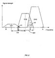
- the spectrum of the radio interface may be subdivided into a plurality of adjacent frequency bands f0-f1, f1-f2, and f2-f3 as shown in Fig. 2 .
- the individual frequency bands f0-f1, f1-f2, and f2-f3 are assigned to the corresponding radio channels CH1, CH2 and CH3, respectively.
- the radio channels CH1, CH2 and CH3 are assigned within the communications network in such a way that, for example, the radio channel CH2 is available for connections between the base station 20 and the corresponding mobile station 40 in the radio cell 30.
- other radio channels CH1, CH3, etc. will be allocated.
- Signals S including data or information are transmitted via the radio channel CH2 from the base station BS 20.
- the base station BS 21 is assumed to be the base station transmitting on the channel CH1, which is adjacent to channel CH2, for communication with the mobile station MS 41.
- a transmitted signal S which is the communication over the radio channel CH2 between the base station BS 20 and the mobile station MS 40 is disturbed by interfering signals IS1 on the adjacent radio channel CH1 of the base station BS 21.
- the radio channels CH1 and CH2 are adjacent radio frequency channels, so that adjacent-channel interference may be present in the lower frequency band area 51 of the desired radio channel CH2.
- the communication over the radio channel CH2 may be disturbed by other interfering signals IS3 on the radio channel CH3.
- the signal-to-adjacent interference ratio that is the ratio between the power of the desired signal and that of adjacent-channel interference, may have significant impact on the performance of the mobile station MS 40, and thus the frequency planning and spectrum efficiency of the communication network.
- ACI may occur in the lower frequency end area 51 as well as in the upper frequency end area 52 of the frequency spectrum of the radio channel CH2, as a result of the lower frequency adjacent channel CH1 and the upper frequency adjacent channel CH3, respectively.
- the ACI in the lower frequency end area 51 may be negligible.
- the ACI in the upper frequency end area 52 is still very strong.
- the filter device 403 may be adapted to perform selective and/or adaptive filtering of the baseband signal s 1 of the received signal S in order to suppress effects of Adjacent-Channel Interference of the received signal S.
- Fig. 3 illustrates an embodiment of the filter device 403 of the mobile station 40 in Fig. 1 .
- the filter device 403 may comprise a receiver (Rx) filter 4031, such as a low-pass filter, for receiving discrete-time baseband signals s 1 which have been generated by way of the analog-to-digital conversion performed by the A/D-converter 402 shown in Fig. 1 .
- Rx receiver
- ACI that appears in the received signal S may propagate through the RF receiver unit 401 and the A/D-converter 402.
- any effects of the ACI may still be present in the discrete-time baseband signals s 1 that are output from the A/D-converter 402 and subsequently input to the Rx filter 4031 of the filter device 403.
- the filter device 403 may comprise an interference filter 4032 for combined or integrated upper and lower frequency band filtering of the received discrete-time baseband signal s, which is the output from the Rx filter 4031.
- the interference filter 4032 may be a digital filter.
- digital filters refer to the filtering of sampled-data or discrete-time signals.
- the interference filter 4032 may, for example, be a digital finite impulse response (FIR) filter, i.e. a filter with only zeros but no poles in the complex (z) domain, such as a low order digital FIR filter.
- FIR digital finite impulse response
- the FIR filter operation may be a computational process carried out either by dedicated hardware or by execution of a sequence of instructions by programmable logic. It may also be a combination of hardware and software, or even a computer program product comprising computer program means for executing the computational process. Thereby, an input sequence of numbers is converted by a transfer function into an output sequence of numbers. Transfer functions refer to the frequency characteristics of the digital FIR filter used. Examples of transfer functions may include low-pass, highpass, band-pass functions, etc. Digital filter computations include digital addition, digital multiplication of signal values by constants, and the insertion of delay stages.
- an asymmetrical digital 2 nd order FIR filter whose frequency response is asymmetrical with regard to the zero-frequency of the baseband signal s (or the center-frequency of the received signal S), is designed for suppressing the effects of ACI at the upper frequency band, i.e. ACI effects from the upper channel CH3, see Fig. 2 .
- ⁇ and ⁇ are the normalized frequencies of two respective zeros
- a and b are coefficients of the FIR filter and j is the imaginary operator.
- the frequency response may require that the normalized frequencies of two respective zeros lie in the range ⁇ 2 ⁇ ⁇ , ⁇ ⁇ ⁇ .
- the normalized frequencies ⁇ , ⁇ of the respective zeros may vary to a certain extent around the frequency boundary between the desired channel CH2 and the upper adjacent channel, CH3.
- the normalized frequencies of the zeros are preferably not identical. One of them may be exactly at the frequency boundary.
- a certain constraint is used as a means for improving the computational efficiency of the digital 2 nd order FIR filter.
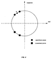
- Fig. 4 illustrates the locations of the normalized four interrelated zeros in the complex plane, where B represents the normalized frequency boundary. It shows that the normalized zeros of the upper and lower frequency band filters should be exactly on the unit circle to be most effective. Further, it illustrates that the four zeros are paired in a mirrored position, i.e. the zeros for the lower frequency band filter are in the mirrored position of the zeros for the upper frequency band filter about the real axis. Nevertheless, the normalized frequencies of the respective zeros may vary to a certain extent around the normalized frequency boundary B.
- the symmetrical nature of the expressions (4) and (5) is such that these two expressions can be advantageously combined or integrated in order to obtain a digital Single-Input-Multiple-Output (SIMO) interference filter 4032.
- the SIMO interference filter 4032 of this embodiment is capable of simultaneously generating two separate signals, i.e. a first signal x filtered at the upper frequency band and a second signal y filtered at the lower frequency band, wherein the first signal x is separate from the second signal y.
- the upper frequency band FIR filter i.e. expression (4)
- the lower frequency band FIR filter i.e.
- r the real part of the complex signal
- i the imaginary part of the complex signal.
- x r n s r n + s i ⁇ n - 2 + ⁇ ⁇ s r ⁇ n - 1 + s i ⁇ n - 1
- x i n s i n - s r ⁇ n - 2 - ⁇ ⁇ s r ⁇ n - 1 - s i ⁇ n - 1
- y r n s r n - s i ⁇ n - 2 + ⁇ ⁇ s r ⁇ n - 1 - s i ⁇ n - 1
- y i n s i n + s r ⁇ n - 2 + ⁇ ⁇ s ⁇ n - 1 + s i ⁇ n - 1 + s i ⁇ n - 1 +
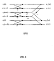
- the expressions (9) can be depicted in a Signal Flow Graph (SFG).
- SFG shown in Fig. 5 illustrates that the operational sharing between the upper and lower band signal filtering yields a "butterfly" structure of the digital SIMO interference filter 4032.
- ⁇ the four interrelated zeros of the transfer function (6) of the SIMO interference filter 4032, i.e. ⁇ and ⁇ for the normalized frequencies of the two respective zeros designed for upper band filtering and - ⁇ and - ⁇ for the normalized frequencies of the two respective zeros designed for lower band filtering, can be found by first defining ⁇ .
- SIMO interference filters may have different characteristics when ⁇ is chosen differently. Consequently, ⁇ is not fixed.
- FIG. 6 Another embodiment of the present invention is schematically shown in Fig. 6 .
- the elements in Fig. 6 having corresponding elements in Fig. 3 operate and interact similarly to the description with reference to Fig. 3 .
- the filter device 403 of Fig. 6 further comprises a de-rotator 6034 for de-rotating a received baseband signal s 2 , which is the output from the Rx filter 4031.
- the filter device is intended for use in a receiver of the mobile station MS 40 in GSM network.
- f(z) is the transfer function configured for the filtering at the upper frequency band
- g(z) is the transfer function configured for the filtering at the lower frequency band
- ⁇ ⁇ - ⁇ G
- ⁇ ⁇ - ⁇ G
- - ⁇ - ⁇ - ⁇ G
- ⁇ ', ⁇ ' - ⁇ ',- ⁇ ' are the normalized frequencies of the two pairs of the zeros after de-rotation.
- a certain constraint can be used as a means for improving the computational efficiency of the digital 2 nd order FIR filters in expressions (10).
- x r n s r n - ⁇ ⁇ s r ⁇ n - 1 + ⁇ ⁇ s i ⁇ n - 1 - s i ⁇ n - 2
- x i n s i n - ⁇ ⁇ s r ⁇ n - 1 - ⁇ ⁇ s i ⁇ n - 1 + s r ⁇ n - 2
- y r n s r n + ⁇ ⁇ s r ⁇ n - 1 + ⁇ ⁇ s i ⁇ n - 1 + s i ⁇ n - 2
- y i n s i n - ⁇ ⁇ s r ⁇ n - 1 + ⁇ ⁇ s i ⁇ n - 1 + ⁇ s i ⁇ n - 2
- r the real part of the complex signal
- i the imaginary part of the complex signal.
- x r n s r n - s i ⁇ n - 2 - ⁇ ⁇ s r ⁇ n - 1 - s i ⁇ n - 1
- x i n s i n + s r ⁇ n - 2 - ⁇ ⁇ s r ⁇ n - 1 + s i ⁇ n - 1
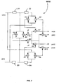
- Fig. 7 illustrates a block diagram of an example of a realization of the digital SIMO interference filter 6032 in accordance with the expressions (16).
- the digital SIMO interference filter 6032 may comprise four delay elements D1-D4, ten adder elements A1-A10, and two multiplier elements M1-M2.
- M1 and M2 the delay elements required for dividing the digital SIMO interference filter 6032 into two filtering results.
- M1 and M2 the real multiplications
- A1-A10 ten real additions per complex sample are required for parallel computation of both upper and lower band filtering.
- this interference filter 6032 it is possible to get two filtering results in parallel, i.e. one upper band filtering result and one lower band filtering result.
- the constraint (11) was not applied to the digital FIR filter according to the transfer function (10), it
- the expressions (16) may alternatively be depicted in an SFG.
- the SFG shown in Fig. 8 illustrates again that the operational sharing between the upper and lower band signal filtering yields a "butterfly" structure of the digital SIMO interference filter 6032.
- the bandwidth BW of the desired signal is normally 271 kHz while the channel spacing CS between two adjacent channels is normally about 200 kHz, see fig. 2 .
- the normalized frequency boundary between the desired channel and the upper/lower adjacent channel is at: 200 271 ⁇ ⁇ ⁇ 100 135 ⁇ ⁇ .
- the normalized frequencies of the zeros, i.e, ⁇ and ⁇ , should be close to the normalized frequency boundary of 100 135 ⁇ ⁇ .
- ⁇ the four interrelated normalized frequencies of the zeros of the SIMO interference filter 6032, i.e. ⁇ and ⁇ for upper frequency band and - ⁇ and - ⁇ for the lower frequency band, can be found by first defining ⁇ .
- ⁇ does not need to be fixed and could preferably be tested and evaluated thoroughly in each specific case.
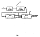
- FIG. 9 yet another embodiment of the present invention is schematically shown.
- the elements in Fig. 9 having corresponding elements in Fig. 3 and 6 operate and interact similarly to the description with reference to Figs. 3 and 6 .
- the filter device 403 differs from the filter device previously described with reference to Fig. 6 in that the filter device 403 is intended for use in a receiver of the mobile station 40 in EDGE network.
- the received signal is 8-PSK (8-state Phase Shift Keying) modulated
- the received signal may be de-rotated by 3 ⁇ ⁇ 8 by means of a de-rotator 9034.
- x r n s r n + ⁇ ⁇ s i ⁇ n - 1 - s r ⁇ n - 2
- x i n s i n - ⁇ ⁇ s r ⁇ n - 1 - s i ⁇ n - 2
- y r n s r n + ⁇ ⁇ s r ⁇ n - 1 + ⁇ ⁇ s i ⁇ n - 1 + s i ⁇ n - 2
- y i n s i n - ⁇ ⁇ s r ⁇ n - 1 - ⁇ ⁇ s i ⁇ n - 1 - s r ⁇ n - 2
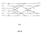
- the expressions (22) can be depicted in a SFG.
- the SFG shown in Fig. 10 illustrates the operational sharing between the upper and lower band filtering that is provided by the SIMO interference filter 9032 according to this embodiment.
- ⁇ 110 135 ⁇ ⁇ , so ⁇ ⁇ 125 135 ⁇ ⁇ .
- Fig. 11 shows typical characteristics of the SIMO interference filter with one input signal s and two output signals x, y according to embodiments of the interference filter 4032, 6032 and 9032.
- the interference filter generates simultaneously two separate signals, i.e. a first signal x filtered at an upper frequency band and a second separate signal y filtered at a lower frequency band, wherein the first signal is separate from the second signal.
- the frequency responses of the upper frequency band filter and the lower frequency band filter are asymmetrical with regard to the center frequency of the received signal. This makes it possible to avoid damaging the desired signal while suppressing ACI.
- the significant operational sharing of the SIMO interference filter 4032, 6032 and 9032 is an advantage, because it requires few digital multiplications and additions per complex sample. Thus, it makes it possible to suppress potential ACI effects from adjacent channels CH1 and CH3 without excessive computational complexity and associated power consumption. In conclusion, it is possible to provide a SIMO interference filter for suppressing ACI effects that is computationally efficient and at the same time not damaging the desired signal.
- the filter device 403 may further comprise a selector 4033.
- the selector 4033 may be adapted to receive the baseband signal s that is output from the Rx filter 4031.
- the selector 4033 may be adapted to receive the baseband signal s that is output from the de-rotator 6034.
- the selector 4033 may be adapted to receive the baseband signal s that is output from the de-rotator 9034.
- the selector 4033 may be adapted to receive the upper band filtered signal x, and the lower band filtered signal y, respectively, that are outputs from the SIMO interference filter 4032, 6032 or 9032.
- the selector 4033 is adapted to select one of the signals for further processing, e.g. based on noise estimation, once the selector has received these signals.
- the noise estimation may be performed in such a way that the noise energy of the baseband signal s, the upper band filtered signal x, and the lower band filtered signal y, respectively, are each estimated by the selector 4033.
- the estimation of the noise energy may, for example, be performed by channel estimation utilizing a transmitted Training Sequence Code TSC that is known to the selector 4033. Thereafter, the signal with the lowest estimated noise power level may be selected by the selector 4033 to be output. Subsequently, the output from the filter device 403 will be input to the equalizer 404.
- an adaptive scheme for ACI rejection may be obtained.
- the selector 4033 may select the received complex baseband signal s without unnecessarily damaging the received baseband signal.
- the upper band filtered complex signal x is subsequently selected by the selector 4033.
- the lower band filtered complex signal y is selected by the selector to be input to the equalizer.
- the selector 4033 may select any of the signals s, x, or y, wherein s has not been suppressed, x and y have been suppressed, as an output from the filter device 403.
- the selector 4033 Since the selection by the selector 4033 is not only based on the received complex base band signal s but also on the filtering results x, y from the combined/integrated asymmetrical upper and lower frequency band filtering in the SIMO interference filter 4032, 6032 or 9032, it is possible to avoid unnecessarily damaging or impairing the desired baseband signal on the frequency side where no ACI is present or where ACI is negligible. Since the accuracy of the noise estimation relies on the accuracy of the channel estimation, the channel estimation according to embodiments of the invention is made after the ACI suppression, the impact of ACI is minimized.
- the accuracy of channel/noise estimation in the embodiments of the invention is improved. This in turn leads to an easier adaptive decision for the filter device 403 in selecting the signal for further processing.
- the receiver performance in both sensitivity channel and ACI interference channel may be improved.
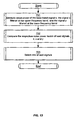
- Fig. 12 illustrates an embodiment of a method for suppressing effects of ACI of a received signal S.
- step 601 a digital baseband signal s of the received signal S is filtered at an upper frequency band and a lower frequency band, respectively.
- a first signal x filtered at the upper frequency band and a second signal y filtered at the lower frequency band, wherein the first signal is separate from the second signal, are simultaneously generated in step 602.
- the steps 601 and 602 may be performed by means of the SIMO interference filter 4032, 6032 or 9032 according to any of the embodiments described above.
- a selection between the baseband signal s and the two separate signals x, y generated in step 602 may be performed.
- Fig. 13 illustrates an embodiment of a method for performing the selection step 603 in Fig. 12 .
- the selection comprises estimating noise power levels of the baseband signal s, the separate signal x filtered at the upper frequency band and the separate signal y filtered at the lower frequency band in step 701. Furthermore, it comprises comparing the respective noise power levels of said signals in step 702, and in response thereto selecting the signal with the lowest noise power level for the further processing in step 703.
- the selection shown in fig. 13 may e.g. be performed by means of the selector 4033 as described above.
- the method shown in Figs. 12 and 13 may, for example, be performed by means of the filter device 403, as described above.
- the present invention may be embedded in a computer program product, which enables implementation of the method and functions described above.
- the invention may be carried out when the computer program product is loaded and run in an apparatus having computer capabilities, such as a processor.
- Computer program, software program, program product, or software in the present context mean any expression, in any programming language, code or notation, of a set of instructions intended to cause a system having a processing capability to perform a particular function directly or after conversion to another language, code or notation.
- the computer program product may be stored on a computer readable medium.
Landscapes
- Engineering & Computer Science (AREA)
- Signal Processing (AREA)
- Computer Networks & Wireless Communication (AREA)
- Physics & Mathematics (AREA)
- Nonlinear Science (AREA)
- Noise Elimination (AREA)
Claims (21)
- Ein Interferenzfilter (4032, 6032, 9032) zum Unterdrücken von Effekten von Nachbarkanalstörungen (51, 52) von einem empfangene Signal (S) in einem Frequenzmultiplexsystem, wobei das Interferenzfilter (4032, 6032, 9032) angepasst ist zum Filtern eines Basisbandsignals (s) des empfangenen Signals (S), dadurch gekennzeichnet, dass das Interferenzfilter (4032, 6032, 9032) ein komplexes digitales Einzeleingang-Mehrfachausgang-, SIMO (engl.: Single-Input-Multiple-Output), -Filter ist, das angepasst ist zum simultanen Erzeugen von einem ersten Signal (x), das bei einem oberen Frequenzband gefiltert wird, und von einem zweiten Signal (y), das bei einem unterem Frequenzband gefiltert wird, durch operativen Zugriff zwischen oberer und unterer Bandsignalfilterung, zu einer Schmetterlingsstruktur führend, wobei das erste Signal (x) von dem zweiten Signal (y) getrennt ist.
- Das Interferenzfilter (4032, 6032, 9032) nach Anspruch 1, wobei das komplexe SIMO-Filter individuelle Frequenzreaktionen für das erste und das zweite Signal (x, y) aufweist, und wobei jede individuelle Frequenzreaktion asymmetrisch mit Bezug auf die Zentralfrequenz des empfangenen Signals (S) ist.
- Das Interferenzfilter (4032, 6032, 9032) nach Anspruch 1 oder 2, wobei das Interferenzfilter (4032, 6032, 9032) mit zwei Paaren von zusammenhängenden Nullen im komplexen Frequenzbereich konfiguriert ist, wobei normalisierte Frequenzen von jedem Paar der zusammenhängenden Nullen von einer gegenseitig abhängigen Bedingung abhängen.
- Das Interferenzfilter (4032, 6032, 9032) nach Anspruch 3, wobei das Interferenzfilter eine Frequenzcharakteristik gemäß


aufweist, wobeif(z) eine Übertragungsfunktion ist, die zum Filtern in dem oberen Frequenzband konfiguriert ist, undg(z) eine Übertragungsfunktion ist, die zum Filtern in dem unteren Frequenzband konfiguriert ist, und wobei α, β und -α, -β die normalisierten Frequenzen der zwei Paare von zusammenhängenden Nullen sind. - Das Interferenzfilter (6032) nach Anspruch 4, wobei das Interferenzfilter (6032) konfiguriert ist zur Verwendung in einer drahtlosen Kommunikationsvorrichtung (40) in einem Globalsystem für ein Mobilkommunikationsnetzwerk.
- Das Interferenzfilter (6032) nach Anspruch 4 oder 5, wobei das Interferenzfilter (6032) konfiguriert ist für empfangene Signale (S), die um

- Das Interferenzfilter (4032, 6032) nach einem der Ansprüche 4 bis 6, wobei die gegenseitig abhängige Bedingung

- Das Interferenzfilter (9032) nach Anspruch 4, wobei das Interferenzfilter (6032) konfiguriert ist zur Verwendung in einer drahtlosen Kommunikationsvorrichtung (40) in erweiterten Daten für ein Globalevolutionsnetzwerk.
- Das Interferenzfilter (9032) nach Anspruch 4 oder 8, wobei das Interferenzfilter (9032) konfiguriert ist für empfangene Signale (S), die um

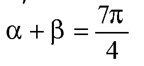
- Das Interferenzfilter (9032) nach einem der Ansprüche 4, 8 oder 9, wobei die gegenseitig abhängige Bedingung
- Eine drahtlose Kommunikationsvorrichtung (40), umfassend das Interferenzfilter (4032, 6032, 9032) nach einem der Ansprüche 1-10.
- Eine Filtervorrichtung (403), umfassend das Interferenzfilter (4032, 6032, 9032) nach einem der Ansprüche 1 bis 10, ferner umfassend eine Auswahleinrichtung (4033), die angepasst ist zum Empfangen des Basisbandsignals (s), des ersten bei dem oberen Frequenzband gefilterten Signals (x) und des zweiten bei dem unteren Frequenzband gefilterten Signals (y), und zum Auswählen eines der Signale (x, y, s) zum Ausgeben basierend auf abgeschätzter Rauschleistung von jedem der Signale.
- Die Filtervorrichtung (403) nach Anspruch 12, wobei die Auswahleinrichtung (4033) angepasst ist zum Abschätzen der Rauschleistungspegel des Basisbandsignals (s), des ersten bei dem oberen Frequenzband gefilterten Signals (x) und des zweiten bei dem unteren Frequenzband gefilterten Signals (y), und zum Vergleichen der entsprechenden Rauschleistungspegel der Signale (x, y, s), und zum Auswählen des Signals mit dem niedrigsten abgeschätzten Rauschleistungspegel.
- Die Filtervorrichtung (403) nach Anspruch 13, wobei die Auswahleinrichtung (4033) angepasst ist zum Abschätzen der Rauschleistungspegel durch eine Kanalabschätzung unter Verwendung eines Trainingssequenzcodes (TSC).
- Eine drahtlose Kommunikationsvorrichtung (40), umfassend die Filtervorrichtung (403) nach einem der Ansprüche 12-14.
- Ein Verfahren zum Unterdrücken von Effekten von Nachbarkanalstörungen (51, 52) von einem empfangene Signal (S) in einem Frequenzmultiplexsystem durch Filtern eines Basisbandsignals (s) eines empfangenen Signals (S),
gekennzeichnet durch:Filtern (601) des Basisbandsignals (s) bei einem oberen Frequenzband und einem untern Frequenzband durch ein komplexes digitales Einzeleingang-Mehrfachausgang-, SIMO (engl.: Single-Input-Multiple-Output), Interferenzfilter (4032, 6032, 9032); undsimultanes Erzeugen (602) eines ersten Signals (x), das bei einem oberen Frequenzband gefiltert wird, und einem zweiten Signal (y), das bei einem unter Frequenzband gefiltert wird, durch operativen Zugriff zwischen oberer und unterer Bandsignalfilterung, zu einer Schmetterlingsstruktur führend, wobei das erste Signal (x) von dem zweiten Signal (y) getrennt ist. - Das Verfahren nach Anspruch 16, wobei jede individuelle Frequenzreaktion der oberen und unteren Frequenzbandfilterung asymmetrisch mit Bezug auf die Zentralfrequenz des empfangenen Signals (S) ist.
- Das Verfahren nach Anspruch 16, wobei das Interferenzfilter (4032, 6032, 9032) mit zwei Paaren von zusammenhängenden Nullen im komplexen Frequenzbereich konfiguriert ist, wobei normalisierte Frequenzen von jedem Paar der zusammenhängenden Nullen von einer gegenseitig abhängigen Bedingung abhängen.
- Das Verfahren nach Anspruch 16, ferner umfassend:Auswählen (603) von einem der Folgenden: das Basisbandsignal (s), das erste bei dem oberen Frequenzband gefilterte Signal (x), das zweite bei dem unteren Frequenzband gefilterte Signal (y).
- Das Verfahren nach Anspruch 19, wobei der Schritt des Auswählens (603) folgendes umfasst:Abschätzen (701) von Rauschleistungspegel des Basisbandsignals (s), des bei dem oberen Frequenzband gefilterten ersten Signals (x) und des bei dem unteren Frequenzband gefilterten zweiten Signals (y);Vergleichen (702) der entsprechenden Rauschleistungspegel der Signale, undAuswählen (703) des Signals mit dem niedrigsten abgeschätzten Rauschleistungspegel.
- Ein Computerprogrammprodukt, umfassend Computerprogrammcodemittel zum Ausführen des Verfahrens nach einem der Ansprüche 16-20, wenn die Computerprogrammcodemittel durch eine elektronische Vorrichtung betrieben werden, die Computerfähigkeiten aufweist.
Priority Applications (8)
| Application Number | Priority Date | Filing Date | Title |
|---|---|---|---|
| AT05024626T ATE445263T1 (de) | 2005-11-11 | 2005-11-11 | Filter und verfahren zur unterdrückung von effekten von nachbarkanalstörungen |
| DE602005017052T DE602005017052D1 (de) | 2005-11-11 | 2005-11-11 | Filter und Verfahren zur Unterdrückung von Effekten von Nachbarkanalstörungen |
| EP05024626A EP1786111B1 (de) | 2005-11-11 | 2005-11-11 | Filter und Verfahren zur Unterdrückung von Effekten von Nachbarkanalstörungen |
| PCT/EP2006/068295 WO2007054538A1 (en) | 2005-11-11 | 2006-11-09 | Filter and method for suppressing effects of adjacent-channel interference |
| KR1020087013890A KR101067581B1 (ko) | 2005-11-11 | 2006-11-09 | 인접 채널 간섭의 효과를 억압하는 필터 및 방법 |
| RU2008123614/09A RU2008123614A (ru) | 2005-11-11 | 2006-11-09 | Фильтр и способ для подавления эффектов помех от соседнего канала |
| US12/093,124 US8059772B2 (en) | 2005-11-11 | 2006-11-09 | Filter and method for suppressing effects of adjacent-channel interference |
| TW095141858A TWI403098B (zh) | 2005-11-11 | 2006-11-10 | 用於抑制相鄰頻道干擾效應之濾波器及方法 |
Applications Claiming Priority (1)
| Application Number | Priority Date | Filing Date | Title |
|---|---|---|---|
| EP05024626A EP1786111B1 (de) | 2005-11-11 | 2005-11-11 | Filter und Verfahren zur Unterdrückung von Effekten von Nachbarkanalstörungen |
Publications (2)
| Publication Number | Publication Date |
|---|---|
| EP1786111A1 EP1786111A1 (de) | 2007-05-16 |
| EP1786111B1 true EP1786111B1 (de) | 2009-10-07 |
Family
ID=35695798
Family Applications (1)
| Application Number | Title | Priority Date | Filing Date |
|---|---|---|---|
| EP05024626A Expired - Lifetime EP1786111B1 (de) | 2005-11-11 | 2005-11-11 | Filter und Verfahren zur Unterdrückung von Effekten von Nachbarkanalstörungen |
Country Status (8)
| Country | Link |
|---|---|
| US (1) | US8059772B2 (de) |
| EP (1) | EP1786111B1 (de) |
| KR (1) | KR101067581B1 (de) |
| AT (1) | ATE445263T1 (de) |
| DE (1) | DE602005017052D1 (de) |
| RU (1) | RU2008123614A (de) |
| TW (1) | TWI403098B (de) |
| WO (1) | WO2007054538A1 (de) |
Cited By (1)
| Publication number | Priority date | Publication date | Assignee | Title |
|---|---|---|---|---|
| EP2823658A1 (de) * | 2012-03-07 | 2015-01-14 | Qualcomm Incorporated | Mehrfunkkoexistenz interferenzabschwächung über frequenzauswahl |
Families Citing this family (18)
| Publication number | Priority date | Publication date | Assignee | Title |
|---|---|---|---|---|
| US7868874B2 (en) | 2005-11-15 | 2011-01-11 | Synaptics Incorporated | Methods and systems for detecting a position-based attribute of an object using digital codes |
| US7804922B2 (en) * | 2007-03-02 | 2010-09-28 | Skyworks Solutions, Inc. | System and method for adjacent channel power detection and dynamic bandwidth filter control |
| US20090190641A1 (en) * | 2008-01-28 | 2009-07-30 | Yen-Wen Yang | Methods and devices for processing signals transmitted via communication system |
| US7920839B2 (en) * | 2008-02-04 | 2011-04-05 | Skyworks Solutions, Inc. | System and method for station detection and seek in a radio receiver |
| US8433001B2 (en) | 2009-09-30 | 2013-04-30 | Motorola Solutions, Inc. | Method and apparatus for mitigation of interference |
| US8477892B2 (en) * | 2009-09-30 | 2013-07-02 | Motorola Solutions, Inc. | Method and apparatus for mitigation of interference |
| US8730204B2 (en) | 2010-09-16 | 2014-05-20 | Synaptics Incorporated | Systems and methods for signaling and interference detection in sensor devices |
| WO2012171189A1 (zh) | 2011-06-15 | 2012-12-20 | 华为技术有限公司 | 一种提高用户通话质量的方法及装置 |
| US8743080B2 (en) | 2011-06-27 | 2014-06-03 | Synaptics Incorporated | System and method for signaling in sensor devices |
| US8766949B2 (en) | 2011-12-22 | 2014-07-01 | Synaptics Incorporated | Systems and methods for determining user input using simultaneous transmission from multiple electrodes |
| US9063608B2 (en) | 2012-06-14 | 2015-06-23 | Synaptics Incorporated | Systems and methods for sensor devices having a non-commensurate number of transmitter electrodes |
| US9088356B2 (en) * | 2012-11-02 | 2015-07-21 | Alcatel Lucent | Translating between testing requirements at different reference points |
| US9176633B2 (en) | 2014-03-31 | 2015-11-03 | Synaptics Incorporated | Sensor device and method for estimating noise in a capacitive sensing device |
| FR3022081B1 (fr) * | 2014-06-05 | 2021-03-05 | Continental Automotive France | Filtrage selectif amont asymetrique en modulation de frequence |
| US10025428B2 (en) | 2015-11-19 | 2018-07-17 | Synaptics Incorporated | Method and apparatus for improving capacitive sensing detection |
| US10019122B2 (en) | 2016-03-31 | 2018-07-10 | Synaptics Incorporated | Capacitive sensing using non-integer excitation |
| EP3261310B1 (de) * | 2016-06-21 | 2019-08-21 | Institut Mines-Telecom / Telecom | Empfängerarchitektur für filterbank-mehrträger-kommunikationssysteme |
| US11463071B2 (en) * | 2018-04-23 | 2022-10-04 | Samsung Electronics Co,. Ltd | Asymmetrical filtering to improve GNSS performance in presence of wideband interference |
Family Cites Families (9)
| Publication number | Priority date | Publication date | Assignee | Title |
|---|---|---|---|---|
| DE4110083A1 (de) | 1991-03-27 | 1992-10-01 | Blaupunkt Werke Gmbh | Verfahren zur nachbarkanalunterdrueckung beim empfang frequenzmodulierter sender |
| FI104019B (fi) * | 1997-06-19 | 1999-10-29 | Nokia Telecommunications Oy | Signaalin ilmaisumenetelmä digitaalisen solukkoradioverkon vastaanottimessa |
| DE19814530A1 (de) * | 1998-04-01 | 1999-10-07 | Bosch Gmbh Robert | Verfahren zur digitalen Übertragung von Daten in einem drahtlosen Kommunikationsnetz und Empfangsgerät zum Empfang von nach dem Verfahren übertragenen Daten |
| DE50013268D1 (de) | 1999-05-21 | 2006-09-14 | Benq Corp | Verfahren zum filtern eines mobilfunksignals und entsprechender mobilfunk-empfänger |
| US6901243B2 (en) | 2001-11-08 | 2005-05-31 | Qualcomm, Incorporated | Method and apparatus for mitigating adjacent channel interference in a wireless communication system |
| KR100547736B1 (ko) * | 2003-06-26 | 2006-01-31 | 삼성전자주식회사 | 다중-채널의 동적 선택을 위한 스위칭 필터 모듈 |
| FR2871966B1 (fr) * | 2004-06-17 | 2006-09-22 | Nortel Networks Ltd | Procede et dispositif de traitement de signal dans un recepteur de radiocommunication |
| US7729679B1 (en) * | 2006-06-09 | 2010-06-01 | Marvell International Ltd. | Dynamic bandwidth filter for an FM receiver |
| JP4337913B2 (ja) * | 2007-06-04 | 2009-09-30 | ソニー株式会社 | 受信装置、プログラム、および受信方法 |
-
2005
- 2005-11-11 EP EP05024626A patent/EP1786111B1/de not_active Expired - Lifetime
- 2005-11-11 AT AT05024626T patent/ATE445263T1/de not_active IP Right Cessation
- 2005-11-11 DE DE602005017052T patent/DE602005017052D1/de not_active Expired - Lifetime
-
2006
- 2006-11-09 US US12/093,124 patent/US8059772B2/en not_active Expired - Fee Related
- 2006-11-09 RU RU2008123614/09A patent/RU2008123614A/ru not_active Application Discontinuation
- 2006-11-09 KR KR1020087013890A patent/KR101067581B1/ko not_active Expired - Fee Related
- 2006-11-09 WO PCT/EP2006/068295 patent/WO2007054538A1/en not_active Ceased
- 2006-11-10 TW TW095141858A patent/TWI403098B/zh not_active IP Right Cessation
Cited By (1)
| Publication number | Priority date | Publication date | Assignee | Title |
|---|---|---|---|---|
| EP2823658A1 (de) * | 2012-03-07 | 2015-01-14 | Qualcomm Incorporated | Mehrfunkkoexistenz interferenzabschwächung über frequenzauswahl |
Also Published As
| Publication number | Publication date |
|---|---|
| KR20080077157A (ko) | 2008-08-21 |
| EP1786111A1 (de) | 2007-05-16 |
| DE602005017052D1 (de) | 2009-11-19 |
| TW200729749A (en) | 2007-08-01 |
| TWI403098B (zh) | 2013-07-21 |
| RU2008123614A (ru) | 2009-12-27 |
| KR101067581B1 (ko) | 2011-09-27 |
| WO2007054538A1 (en) | 2007-05-18 |
| ATE445263T1 (de) | 2009-10-15 |
| US20090135973A1 (en) | 2009-05-28 |
| US8059772B2 (en) | 2011-11-15 |
Similar Documents
| Publication | Publication Date | Title |
|---|---|---|
| EP1786111B1 (de) | Filter und Verfahren zur Unterdrückung von Effekten von Nachbarkanalstörungen | |
| US7471749B2 (en) | Channel parameters estimation in a receiver | |
| US6944434B2 (en) | Method and apparatus for suppressing co-channel interference in a receiver | |
| EP2011241B1 (de) | Nachbarkanalstörungsunterdrückung | |
| US9106298B2 (en) | Suppression of adjacent channel interference by adaptive channel filtering in mobile radio receivers | |
| CN101242626B (zh) | 对接收信号进行滤波的设备及方法 | |
| JP4621683B2 (ja) | ノイズ白色化フィルタリング方法および装置 | |
| US20070121764A1 (en) | Frequency error estimation and correction in a SAIC linear equalizer | |
| EP2162995B1 (de) | Verfahren und vorrichtung zur beseitigung von pilotkanalamplitudenabhängigkeiten aus einem rake-empfängerausgang | |
| US9001877B2 (en) | Signal processing for diversity combining radio receiver | |
| US20060256885A1 (en) | Apparatus and method for estimating carrier-to-interference-and-noise ratio in an orthogonal frequency division multiplexing system | |
| US11336317B2 (en) | Radio communication system, interference suppression method, control circuit, and program storage medium | |
| EP1508201B1 (de) | Farb-störungsidentifikation | |
| CN102739283A (zh) | 时分同步码分多址接收机中基于激活码道选择的联合检测方法 | |
| US20080192870A1 (en) | Apparatus, and associated method, for filtering a receive signal by adaptive operation of an input noise whitening filter | |
| CN112672367A (zh) | 一种谐波干扰消除的方法及装置、接收设备 | |
| EP2425568B1 (de) | Verfahren, vorrichtung und computerprogramm für einen kommunikationsempfänger | |
| US20020064239A1 (en) | DC compensation in direct conversion radio receivers | |
| US7991047B2 (en) | Method for designing a digital reception filter and corresponding receiving device | |
| Schlechter et al. | Overview on blockerdetection in LTE systems | |
| US11700024B2 (en) | System and method implementing excision cancellation technology | |
| CN112688699B (zh) | 一种抗谐波干扰的方法及装置、系统 | |
| EP4319072A1 (de) | System und verfahren zur implementierung einer auf weichen entscheidungen basierenden exzisionsunterdrückungstechnologie | |
| Schlechter | Multiplier free filter bank based concept for blocker detection in LTE systems. | |
| CN100413234C (zh) | Cdma系统的基带接收的同步保持方法与装置 |
Legal Events
| Date | Code | Title | Description |
|---|---|---|---|
| PUAI | Public reference made under article 153(3) epc to a published international application that has entered the european phase |
Free format text: ORIGINAL CODE: 0009012 |
|
| AK | Designated contracting states |
Kind code of ref document: A1 Designated state(s): AT BE BG CH CY CZ DE DK EE ES FI FR GB GR HU IE IS IT LI LT LU LV MC NL PL PT RO SE SI SK TR |
|
| AX | Request for extension of the european patent |
Extension state: AL BA HR MK YU |
|
| 17P | Request for examination filed |
Effective date: 20071116 |
|
| AKX | Designation fees paid |
Designated state(s): AT BE BG CH CY CZ DE DK EE ES FI FR GB GR HU IE IS IT LI LT LU LV MC NL PL PT RO SE SI SK TR |
|
| 17Q | First examination report despatched |
Effective date: 20080408 |
|
| GRAP | Despatch of communication of intention to grant a patent |
Free format text: ORIGINAL CODE: EPIDOSNIGR1 |
|
| GRAS | Grant fee paid |
Free format text: ORIGINAL CODE: EPIDOSNIGR3 |
|
| GRAA | (expected) grant |
Free format text: ORIGINAL CODE: 0009210 |
|
| AK | Designated contracting states |
Kind code of ref document: B1 Designated state(s): AT BE BG CH CY CZ DE DK EE ES FI FR GB GR HU IE IS IT LI LT LU LV MC NL PL PT RO SE SI SK TR |
|
| REG | Reference to a national code |
Ref country code: GB Ref legal event code: FG4D |
|
| REG | Reference to a national code |
Ref country code: CH Ref legal event code: EP |
|
| REG | Reference to a national code |
Ref country code: IE Ref legal event code: FG4D |
|
| REF | Corresponds to: |
Ref document number: 602005017052 Country of ref document: DE Date of ref document: 20091119 Kind code of ref document: P |
|
| PG25 | Lapsed in a contracting state [announced via postgrant information from national office to epo] |
Ref country code: SI Free format text: LAPSE BECAUSE OF FAILURE TO SUBMIT A TRANSLATION OF THE DESCRIPTION OR TO PAY THE FEE WITHIN THE PRESCRIBED TIME-LIMIT Effective date: 20091007 |
|
| NLV1 | Nl: lapsed or annulled due to failure to fulfill the requirements of art. 29p and 29m of the patents act | ||
| LTIE | Lt: invalidation of european patent or patent extension |
Effective date: 20091007 |
|
| PG25 | Lapsed in a contracting state [announced via postgrant information from national office to epo] |
Ref country code: SE Free format text: LAPSE BECAUSE OF FAILURE TO SUBMIT A TRANSLATION OF THE DESCRIPTION OR TO PAY THE FEE WITHIN THE PRESCRIBED TIME-LIMIT Effective date: 20091007 Ref country code: LT Free format text: LAPSE BECAUSE OF FAILURE TO SUBMIT A TRANSLATION OF THE DESCRIPTION OR TO PAY THE FEE WITHIN THE PRESCRIBED TIME-LIMIT Effective date: 20091007 Ref country code: PT Free format text: LAPSE BECAUSE OF FAILURE TO SUBMIT A TRANSLATION OF THE DESCRIPTION OR TO PAY THE FEE WITHIN THE PRESCRIBED TIME-LIMIT Effective date: 20100208 Ref country code: ES Free format text: LAPSE BECAUSE OF FAILURE TO SUBMIT A TRANSLATION OF THE DESCRIPTION OR TO PAY THE FEE WITHIN THE PRESCRIBED TIME-LIMIT Effective date: 20100118 Ref country code: IS Free format text: LAPSE BECAUSE OF FAILURE TO SUBMIT A TRANSLATION OF THE DESCRIPTION OR TO PAY THE FEE WITHIN THE PRESCRIBED TIME-LIMIT Effective date: 20100207 Ref country code: FI Free format text: LAPSE BECAUSE OF FAILURE TO SUBMIT A TRANSLATION OF THE DESCRIPTION OR TO PAY THE FEE WITHIN THE PRESCRIBED TIME-LIMIT Effective date: 20091007 |
|
| PG25 | Lapsed in a contracting state [announced via postgrant information from national office to epo] |
Ref country code: LV Free format text: LAPSE BECAUSE OF FAILURE TO SUBMIT A TRANSLATION OF THE DESCRIPTION OR TO PAY THE FEE WITHIN THE PRESCRIBED TIME-LIMIT Effective date: 20091007 Ref country code: PL Free format text: LAPSE BECAUSE OF FAILURE TO SUBMIT A TRANSLATION OF THE DESCRIPTION OR TO PAY THE FEE WITHIN THE PRESCRIBED TIME-LIMIT Effective date: 20091007 |
|
| PG25 | Lapsed in a contracting state [announced via postgrant information from national office to epo] |
Ref country code: BE Free format text: LAPSE BECAUSE OF FAILURE TO SUBMIT A TRANSLATION OF THE DESCRIPTION OR TO PAY THE FEE WITHIN THE PRESCRIBED TIME-LIMIT Effective date: 20091007 Ref country code: MC Free format text: LAPSE BECAUSE OF NON-PAYMENT OF DUE FEES Effective date: 20091130 Ref country code: AT Free format text: LAPSE BECAUSE OF FAILURE TO SUBMIT A TRANSLATION OF THE DESCRIPTION OR TO PAY THE FEE WITHIN THE PRESCRIBED TIME-LIMIT Effective date: 20091007 |
|
| REG | Reference to a national code |
Ref country code: CH Ref legal event code: PL |
|
| PG25 | Lapsed in a contracting state [announced via postgrant information from national office to epo] |
Ref country code: NL Free format text: LAPSE BECAUSE OF FAILURE TO SUBMIT A TRANSLATION OF THE DESCRIPTION OR TO PAY THE FEE WITHIN THE PRESCRIBED TIME-LIMIT Effective date: 20091007 Ref country code: RO Free format text: LAPSE BECAUSE OF FAILURE TO SUBMIT A TRANSLATION OF THE DESCRIPTION OR TO PAY THE FEE WITHIN THE PRESCRIBED TIME-LIMIT Effective date: 20091007 Ref country code: BG Free format text: LAPSE BECAUSE OF FAILURE TO SUBMIT A TRANSLATION OF THE DESCRIPTION OR TO PAY THE FEE WITHIN THE PRESCRIBED TIME-LIMIT Effective date: 20100107 Ref country code: DK Free format text: LAPSE BECAUSE OF FAILURE TO SUBMIT A TRANSLATION OF THE DESCRIPTION OR TO PAY THE FEE WITHIN THE PRESCRIBED TIME-LIMIT Effective date: 20091007 Ref country code: EE Free format text: LAPSE BECAUSE OF FAILURE TO SUBMIT A TRANSLATION OF THE DESCRIPTION OR TO PAY THE FEE WITHIN THE PRESCRIBED TIME-LIMIT Effective date: 20091007 |
|
| PLBE | No opposition filed within time limit |
Free format text: ORIGINAL CODE: 0009261 |
|
| STAA | Information on the status of an ep patent application or granted ep patent |
Free format text: STATUS: NO OPPOSITION FILED WITHIN TIME LIMIT |
|
| PG25 | Lapsed in a contracting state [announced via postgrant information from national office to epo] |
Ref country code: SK Free format text: LAPSE BECAUSE OF FAILURE TO SUBMIT A TRANSLATION OF THE DESCRIPTION OR TO PAY THE FEE WITHIN THE PRESCRIBED TIME-LIMIT Effective date: 20091007 Ref country code: CZ Free format text: LAPSE BECAUSE OF FAILURE TO SUBMIT A TRANSLATION OF THE DESCRIPTION OR TO PAY THE FEE WITHIN THE PRESCRIBED TIME-LIMIT Effective date: 20091007 |
|
| 26N | No opposition filed |
Effective date: 20100708 |
|
| PG25 | Lapsed in a contracting state [announced via postgrant information from national office to epo] |
Ref country code: CH Free format text: LAPSE BECAUSE OF NON-PAYMENT OF DUE FEES Effective date: 20091130 Ref country code: LI Free format text: LAPSE BECAUSE OF NON-PAYMENT OF DUE FEES Effective date: 20091130 Ref country code: IE Free format text: LAPSE BECAUSE OF NON-PAYMENT OF DUE FEES Effective date: 20091111 Ref country code: GR Free format text: LAPSE BECAUSE OF FAILURE TO SUBMIT A TRANSLATION OF THE DESCRIPTION OR TO PAY THE FEE WITHIN THE PRESCRIBED TIME-LIMIT Effective date: 20100108 |
|
| PG25 | Lapsed in a contracting state [announced via postgrant information from national office to epo] |
Ref country code: IT Free format text: LAPSE BECAUSE OF FAILURE TO SUBMIT A TRANSLATION OF THE DESCRIPTION OR TO PAY THE FEE WITHIN THE PRESCRIBED TIME-LIMIT Effective date: 20091007 |
|
| PG25 | Lapsed in a contracting state [announced via postgrant information from national office to epo] |
Ref country code: LU Free format text: LAPSE BECAUSE OF NON-PAYMENT OF DUE FEES Effective date: 20091111 |
|
| PG25 | Lapsed in a contracting state [announced via postgrant information from national office to epo] |
Ref country code: HU Free format text: LAPSE BECAUSE OF FAILURE TO SUBMIT A TRANSLATION OF THE DESCRIPTION OR TO PAY THE FEE WITHIN THE PRESCRIBED TIME-LIMIT Effective date: 20100408 |
|
| PG25 | Lapsed in a contracting state [announced via postgrant information from national office to epo] |
Ref country code: TR Free format text: LAPSE BECAUSE OF FAILURE TO SUBMIT A TRANSLATION OF THE DESCRIPTION OR TO PAY THE FEE WITHIN THE PRESCRIBED TIME-LIMIT Effective date: 20091007 |
|
| PG25 | Lapsed in a contracting state [announced via postgrant information from national office to epo] |
Ref country code: CY Free format text: LAPSE BECAUSE OF FAILURE TO SUBMIT A TRANSLATION OF THE DESCRIPTION OR TO PAY THE FEE WITHIN THE PRESCRIBED TIME-LIMIT Effective date: 20091007 |
|
| REG | Reference to a national code |
Ref country code: FR Ref legal event code: PLFP Year of fee payment: 11 |
|
| REG | Reference to a national code |
Ref country code: FR Ref legal event code: PLFP Year of fee payment: 12 |
|
| REG | Reference to a national code |
Ref country code: FR Ref legal event code: PLFP Year of fee payment: 13 |
|
| PGFP | Annual fee paid to national office [announced via postgrant information from national office to epo] |
Ref country code: DE Payment date: 20181128 Year of fee payment: 14 |
|
| PGFP | Annual fee paid to national office [announced via postgrant information from national office to epo] |
Ref country code: GB Payment date: 20181127 Year of fee payment: 14 Ref country code: FR Payment date: 20181127 Year of fee payment: 14 |
|
| REG | Reference to a national code |
Ref country code: DE Ref legal event code: R119 Ref document number: 602005017052 Country of ref document: DE |
|
| GBPC | Gb: european patent ceased through non-payment of renewal fee |
Effective date: 20191111 |
|
| PG25 | Lapsed in a contracting state [announced via postgrant information from national office to epo] |
Ref country code: FR Free format text: LAPSE BECAUSE OF NON-PAYMENT OF DUE FEES Effective date: 20191130 Ref country code: DE Free format text: LAPSE BECAUSE OF NON-PAYMENT OF DUE FEES Effective date: 20200603 Ref country code: GB Free format text: LAPSE BECAUSE OF NON-PAYMENT OF DUE FEES Effective date: 20191111 |