EP1786128A1 - Appareil de suppression de puissance de crete et procede de suppression de puissance de crete - Google Patents
Appareil de suppression de puissance de crete et procede de suppression de puissance de crete Download PDFInfo
- Publication number
- EP1786128A1 EP1786128A1 EP05772709A EP05772709A EP1786128A1 EP 1786128 A1 EP1786128 A1 EP 1786128A1 EP 05772709 A EP05772709 A EP 05772709A EP 05772709 A EP05772709 A EP 05772709A EP 1786128 A1 EP1786128 A1 EP 1786128A1
- Authority
- EP
- European Patent Office
- Prior art keywords
- peak power
- band
- distortion component
- signal
- section
- Prior art date
- Legal status (The legal status is an assumption and is not a legal conclusion. Google has not performed a legal analysis and makes no representation as to the accuracy of the status listed.)
- Withdrawn
Links
Images



Classifications
-
- H—ELECTRICITY
- H03—ELECTRONIC CIRCUITRY
- H03G—CONTROL OF AMPLIFICATION
- H03G11/00—Limiting amplitude; Limiting rate of change of amplitude
-
- H—ELECTRICITY
- H04—ELECTRIC COMMUNICATION TECHNIQUE
- H04B—TRANSMISSION
- H04B1/00—Details of transmission systems, not covered by a single one of groups H04B3/00 - H04B13/00; Details of transmission systems not characterised by the medium used for transmission
- H04B1/02—Transmitters
- H04B1/04—Circuits
- H04B1/0475—Circuits with means for limiting noise, interference or distortion
-
- H—ELECTRICITY
- H04—ELECTRIC COMMUNICATION TECHNIQUE
- H04L—TRANSMISSION OF DIGITAL INFORMATION, e.g. TELEGRAPHIC COMMUNICATION
- H04L27/00—Modulated-carrier systems
- H04L27/26—Systems using multi-frequency codes
- H04L27/2601—Multicarrier modulation systems
- H04L27/2614—Peak power aspects
- H04L27/2623—Reduction thereof by clipping
-
- H—ELECTRICITY
- H04—ELECTRIC COMMUNICATION TECHNIQUE
- H04B—TRANSMISSION
- H04B2201/00—Indexing scheme relating to details of transmission systems not covered by a single group of H04B3/00 - H04B13/00
- H04B2201/69—Orthogonal indexing scheme relating to spread spectrum techniques in general
- H04B2201/707—Orthogonal indexing scheme relating to spread spectrum techniques in general relating to direct sequence modulation
- H04B2201/70706—Orthogonal indexing scheme relating to spread spectrum techniques in general relating to direct sequence modulation with means for reducing the peak-to-average power ratio
Definitions
- the present invention relates to peak power suppression apparatus and peak power suppression methods. More particularly, the present invention relates to peak power suppression apparatus and peak power suppression methods used in an OFDM (Orthogonal Frequency Division Multiplex) scheme wireless transmission apparatus.
- OFDM Orthogonal Frequency Division Multiplex
- a multi-carrier signal with a plurality of subcarriers arranged orthogonal on the frequency axis is used with the OFDM scheme.
- the multi-carrier signal is obtained by combining a plurality of carriers, which often produces high peak power.
- a PAPR Peak to Average Power Ratio
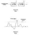
- FIG. 1 is a block diagram showing an example configuration of a conventional peak power suppression apparatus that implements the clipping and filtering method.
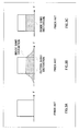
- the amplitude value is restricted by the clipping of clipping section 11. If this process is viewed at the frequency axis, the distortion component caused by the clipping of the transmission signal having the spectrum shown in FIG.3A appears inside and outside the band of the transmission signal, as shown in FIG.3B. The distortion component outside of the band that may interfere with adjacent channels is eliminated by filtering section 12 to attain a transmission signal having a spectrum as shown in FIG.3C.
- the distortion component outside of the band of the transmission signal can be eliminated by filtering
- the distortion component inside the band of the transmission signal is not eliminated by filtering and remains as it is in the transmission signal. Therefore, if signals with the distortion component inside the band are sent to a reception apparatus, there is a problem that the reception error rate characteristic on the reception apparatus is degraded.
- It is therefore an object of the present invention is to provide a peak power suppression apparatus and a peak power suppression method that improve the reception error rate characteristic on the reception apparatus.
- the peak power suppression apparatus of the present invention employs a configuration having: a suppression section that suppresses a peak power of a signal; a sampling section that samples a distortion component inside a band of the signal whose peak power is suppressed; and a removing section that removes the sampled distortion component inside the band from the signal whose peak power is suppressed.
- the peak power suppression apparatus of the present invention has: suppressing a peak power of a signal; sampling a distortion component inside a band of the signal whose peak power is suppressed; and removing the sampled distortion component inside the band from the signal whose peak power is suppressed.
- the reception error rate characteristic of a reception apparatus is improved.
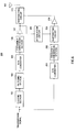
- FIG.4 is a block diagram of a configuration of a wireless transmission apparatus that adopts the peak power suppression apparatus according to a first embodiment of the present invention.
- Wireless transmission apparatus 100 of FIG. 4 has: clipping section 102; filtering section 103; subtracting circuit 104; D/A converter 105; frequency conversion section 106; power amplifier 107; D/A converter 108; frequency conversion section 109; power amplifier 110; subtracting circuit 111; and antenna 112.
- Clipping section 102 as the suppression means clips the amplitude component of the transmission signal above a threshold value. This enables the peak power of the transmission signal to be suppressed. Filtering of the output signals of the clipping section 102 is performed at filtering section 103 and the distortion component outside the band of the transmission signal is removed. The output signal of filtering section 103 is converted from a digital signal to an analog signal at D/A converter 105. The output signal of D/A converter 105 is frequency-converted to a RF (radio frequency) signal of from the baseband signal, at frequency conversion section 106. The output signal of frequency conversion section 106 is amplified at power amplifier 107 as a first amplification means belonging to a main transmission system.
- the original transmission signal specifically the transmission signal just prior to filtering is subtracted from the output signal of filtering section 103 at subtracting circuit 104 as the sampling means, and the distortion component inside the band of the transmission signal is sampled.
- the output signal of subtracting circuit 104 specifically the distortion component inside the band, is converted from a digital signal to an analog signal at D/A converter 108.
- the output signal of D/A converter 108 is frequency-converted to an RF signal from the baseband signal, at frequency conversion section 109.
- the output signal of frequency conversion section 109 is amplified at power amplifier 110 as a second amplifying means belonging to a sub-transmission system.
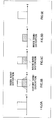
- the transmission signal inputted to clipping section 102 has a spectrum as shown in FIG. 5A, for example. Also, the transmission signal undergoes clipping at clipping section 102. In this process, the amplitude component that exceeds a predetermined threshold value is restricted, whereby the peak power is suppressed.
- the aforementioned threshold value is determined based on the PAPR value determined according to the design. For example, if the PAPR value is 6 dB, the threshold value is set to 6 dB higher than the average signal power. As shown in FIG. 5B, the distortion component is included both inside and outside the band of the transmission signal, in the clipped transmission signal.
- the clipped transmission signal undergoes filtering at filter section 103.
- the distortion component outside the band is removed, as shown in FIG. 5C.
- the distortion component inside the band remains in the transmission signal.
- the transmission signal outputted from filtering section 103 undergoes D/A conversion and frequency conversion at D/A converter 105 and frequency conversion section 106, and is then amplified by power amplifier 107.
- the original transmission signal from the output signal of filtering section 103 is subtracted at subtracting circuit 104.
- the result is that the distortion component inside the band of the transmission signal is removed, as shown in FIG.5D.
- the removed distortion component inside the band is amplified at power amplifier 110. Note that because only the distortion component inside the band is amplified at power amplifier 110 of the sub-transmission system, it is acceptable to use an amplifier having a lower output characteristic in comparison to power amplifier 107 of the main transmission system.
- distortion component inside the band as the output signal of power amplifier 110 is subtracted from the transmission signal as the output signal of power amplifier 107, at subtracting circuit 111. This removes the distortion component inside the band from the transmission signal.
- the transmission signal obtained as a result of this has a spectrum as shown in FIG.5E, for example.
- the distortion component inside the band is removed from the transmission signal whose peak power is suppressed, according to the present invention. Therefore, the reception error rate characteristic of the reception apparatus is improved.
- the distortion component inside the band is removed from the amplified transmission signal, peak power is regenerated on the time axis by the removal of the distortion component inside the band and the PAPR value is increased.
- the PAPR value can be suppressed to below a set value at the input stage of power amplifier 107. Therefore, even if the PAPR value is increased after power amplifier 107, it is possible to prevent the affects of setting a back-off setting of power amplifier 107, specifically, a back-off value that indicates a difference between the maximum amplitude level for maintaining the linearity of power amplifier 107 and a saturation power level.
- FIG.6 is a block diagram of a configuration of a wireless transmission apparatus that applies the peak power suppression apparatus according to a second embodiment of the present invention.
- wireless transmission apparatus 200 of FIG.6 has the same basic configuration as wireless transmission apparatus 100 explained in relation to the first embodiment, so the same components are assigned same reference numerals. Thus, explanations thereof will be omitted.
- D/A converter 201 instead of subtracting circuit 104; D/Aconverter 108; frequency conversion section 109 and power amplifier 110 explained in relation to the first embodiment, D/A converter 201; frequency conversion section 202, subtracting circuit 203 and power amplifier 204 are provided on wireless transmission apparatus 200, and attenuating circuit 205 is also added.
- the original signal is converted from a digital signal to an analog signal at D/A converter 201.
- the output signal of D/A converter 201 is converted to an RF signal from the baseband signal, at frequency conversion section 202.
- the output signal of power amplifier 107 is attenuated at attenuating circuit 205.
- the output signal of frequency conversion section 202 is subtracted from the output signal of power amplifier 107 at subtracting circuit 203 as the sampling means, and the distortion component inside the band of the transmission signal is sampled. At this time, the non-linear distortion component of power amplifier 107 is also sampled.
- the output signal of subtracting circuit 203 is amplified at power amplifier 204 as a second amplifying means belonging to the sub-transmission system.
- this process is performed at the RF band in this embodiment of the present invention.
- the output signal of power amplifier 107 is attenuated at attenuating circuit 205.
- the transmission signal that underwent D/A conversion and frequency conversion at D/A converter 201 and frequency conversion section 202, is subtracted from the attenuated signal.
- the distortion component inside the band of the transmission signal is removed.
- the non-linear distortion component generated at power amplifier 107 of the main transmission system is removed.
- the removed distortion component inside the band and the non-linear distortion component are amplified at power amplifier 204. Because only the distortion component inside the band and the non-linear distortion component are amplified at power amplifier 204 of the sub-transmission system, it is acceptable to use an amplifier having a lower output characteristic in comparison to power amplifier 107 of the main transmission system.
- the distortion component inside the band as the output signal of power amplifier 204 and non-linear distortion component are subtracted from the transmission signal as the output signal of power amplifier 107, at subtracting circuit 111. This removes not only the distortion component inside the band, but also the non-linear distortion component from the transmission signal.
- FIG.7 is a block diagram showing a configuration of a wireless transmission apparatus according to a third embodiment of the present invention.
- the wireless transmission apparatus 300 of FIG. 7 has the same basic configuration as wireless transmission apparatus 100 explained in relation to the first embodiment, so the same components are assigned the same reference numerals. Thus, explanations thereof will be omitted.
- Wireless transmission apparatus 300 has power calculation section 301; determining section 302; and power control section 303 in addition to the configuration of wireless transmission apparatus 100.
- Power of the distortion component inside the band is measured at power calculation section 301 as a measuring means. It is determined whether the measured power has exceeded a threshold value at determining section 302.
- the power of power amplifier 110 is controlled at power control section 303 based on the determination result of determining section 302. To explain with more detail, the operations of power amplifier 110 of the sub-transmission system are executed or halted according to the power amount of the distortion component inside the band generated by clipping. If the power amount of the distortion component inside the band is higher than the threshold value set to satisfy a predetermined error rate, the amplification operation of power amplifier 110 is executed. If it is lower, the amplification operation is halted.
- the original signal and the output signal of filtering section 103 are inputted to subtracting circuit 104, and the distortion component inside the band is sampled (step S501). Then, the distortion component inside the band output from subtracting circuit 104 is inputted to power calculation section 301. The amount of power of the distortion component inside the band is measured at power calculation section 301 (step S502). As a calculating method of the amount of power, there is a method for integrating the distortion component signal over one OFDM symbol time, for example.
- the amount of power outputted from power calculation section 301 is inputted to determining section 302. It is then determined at determining section 302 whether or not the amount of power is higher than the threshold value (step S503).
- the threshold value is set so that the error rate based on a distortion component power amount to error rate characteristic found in advance through simulation is below a certain level.
- the determination results of determining section 302 are inputted to power control section 303. If the power amount is higher than the threshold value (S503: YES), the amplification operation of power amplifier 110 is to be executed, and power control section 303 turns on the power to power amplifier 110 (step S504).
- step S503 If the power amount is below the threshold value (S503: NO), the amplification operation of power amplifier 110 is to be halted, and power control section 303 turns off the power to power amplifier 110 (step S505). These operations have the effect of improving the reception error rate characteristic of the reception apparatus, and reduce the power consumption of wireless transmission apparatus 300 compared to normal operation of power amplifier 110.
- Each function block employed in the description of each of the aforementioned embodiments may typically be implemented as an LSI constituted by an integrated circuit. These may be individual chips or partially or totally contained on a single chip.
- LSI is adopted here but this may also be referred to as “IC”, “system LSI”, “super LSI”, or “ultra LSI” depending on differing extents of integration.
- circuit integration is not limited to LSI's, and implementation using dedicated circuitry or general purpose processors is also possible.
- FPGA Field Programmable Gate Array
- reconfigurable processor where connections and settings of circuit cells within an LSI can be reconfigured is also possible.
- the power suppression apparatus and power suppression method of the present invention are applicable to an OFDM scheme wireless transmission apparatus that is used with a cellular telephone or wireless LAN.
Landscapes
- Engineering & Computer Science (AREA)
- Computer Networks & Wireless Communication (AREA)
- Signal Processing (AREA)
- Transmitters (AREA)
- Geophysics And Detection Of Objects (AREA)
- Tone Control, Compression And Expansion, Limiting Amplitude (AREA)
Applications Claiming Priority (2)
| Application Number | Priority Date | Filing Date | Title |
|---|---|---|---|
| JP2004250523 | 2004-08-30 | ||
| PCT/JP2005/014955 WO2006025213A1 (fr) | 2004-08-30 | 2005-08-16 | Appareil de suppression de puissance de crete et procede de suppression de puissance de crete |
Publications (1)
| Publication Number | Publication Date |
|---|---|
| EP1786128A1 true EP1786128A1 (fr) | 2007-05-16 |
Family
ID=35999871
Family Applications (1)
| Application Number | Title | Priority Date | Filing Date |
|---|---|---|---|
| EP05772709A Withdrawn EP1786128A1 (fr) | 2004-08-30 | 2005-08-16 | Appareil de suppression de puissance de crete et procede de suppression de puissance de crete |
Country Status (7)
| Country | Link |
|---|---|
| US (1) | US20080031380A1 (fr) |
| EP (1) | EP1786128A1 (fr) |
| JP (1) | JPWO2006025213A1 (fr) |
| KR (1) | KR20070049160A (fr) |
| CN (1) | CN1993913A (fr) |
| BR (1) | BRPI0515126A (fr) |
| WO (1) | WO2006025213A1 (fr) |
Families Citing this family (22)
| Publication number | Priority date | Publication date | Assignee | Title |
|---|---|---|---|---|
| US8380143B2 (en) | 2002-05-01 | 2013-02-19 | Dali Systems Co. Ltd | Power amplifier time-delay invariant predistortion methods and apparatus |
| US8811917B2 (en) | 2002-05-01 | 2014-08-19 | Dali Systems Co. Ltd. | Digital hybrid mode power amplifier system |
| US7197692B2 (en) * | 2004-06-18 | 2007-03-27 | Qualcomm Incorporated | Robust erasure detection and erasure-rate-based closed loop power control |
| US7594151B2 (en) * | 2004-06-18 | 2009-09-22 | Qualcomm, Incorporated | Reverse link power control in an orthogonal system |
| US8452316B2 (en) * | 2004-06-18 | 2013-05-28 | Qualcomm Incorporated | Power control for a wireless communication system utilizing orthogonal multiplexing |
| US8942639B2 (en) * | 2005-03-15 | 2015-01-27 | Qualcomm Incorporated | Interference control in a wireless communication system |
| US8848574B2 (en) | 2005-03-15 | 2014-09-30 | Qualcomm Incorporated | Interference control in a wireless communication system |
| US7512412B2 (en) * | 2005-03-15 | 2009-03-31 | Qualcomm, Incorporated | Power control and overlapping control for a quasi-orthogonal communication system |
| JP5430938B2 (ja) * | 2005-10-27 | 2014-03-05 | クゥアルコム・インコーポレイテッド | 無線通信システムにおける逆方向リンク・ローディングを推定するための方法及び装置 |
| US7664472B2 (en) * | 2006-02-23 | 2010-02-16 | Raytheon Company | Reducing the peak-to-average power ratio of a signal |
| JP4932389B2 (ja) * | 2006-08-30 | 2012-05-16 | 株式会社エヌ・ティ・ティ・ドコモ | 信号伝送装置および信号伝送方法 |
| US8442572B2 (en) * | 2006-09-08 | 2013-05-14 | Qualcomm Incorporated | Method and apparatus for adjustments for delta-based power control in wireless communication systems |
| US8670777B2 (en) * | 2006-09-08 | 2014-03-11 | Qualcomm Incorporated | Method and apparatus for fast other sector interference (OSI) adjustment |
| JP4755069B2 (ja) * | 2006-11-07 | 2011-08-24 | 三菱電機株式会社 | 送信装置 |
| JP4653724B2 (ja) * | 2006-11-30 | 2011-03-16 | 富士通株式会社 | 信号の帯域外電力を抑圧する送信機 |
| JP5236661B2 (ja) | 2006-12-26 | 2013-07-17 | ダリ システムズ カンパニー リミテッド | 多チャンネル広帯域通信システムにおけるベースバンドプリディストーション線形化の方法及びシステム |
| US9026067B2 (en) | 2007-04-23 | 2015-05-05 | Dali Systems Co. Ltd. | Remotely reconfigurable power amplifier system and method |
| US8271842B2 (en) * | 2008-06-13 | 2012-09-18 | Qualcomm Incorporated | Reducing harq retransmissions using peak power management techniques |
| CN103597807B (zh) | 2010-09-14 | 2015-09-30 | 大理系统有限公司 | 远程可重新配置的分布式天线系统和方法 |
| KR20130106489A (ko) * | 2012-03-20 | 2013-09-30 | 한국전자통신연구원 | 신호왜곡성분 조절 장치 및 방법과 이를 이용한 시스템 |
| US9154168B2 (en) * | 2013-05-14 | 2015-10-06 | Intel IP Corporation | Signal peak-to-average power ratio (PAR) reduction |
| CN113836855B (zh) * | 2021-08-30 | 2023-08-25 | 北京钛方科技有限责任公司 | 饱和信号特征修正方法、装置、电子设备和存储介质 |
Family Cites Families (7)
| Publication number | Priority date | Publication date | Assignee | Title |
|---|---|---|---|---|
| EP1195892B1 (fr) * | 2000-10-06 | 2009-04-22 | Alcatel Lucent | Procédé et émetteur correspondant pour effectuer une prédistorsion d' un signal radio à large bande permettant d'éviter l'écrêtage |
| JP3693331B2 (ja) * | 2002-10-23 | 2005-09-07 | 株式会社日立国際電気 | マルチキャリア信号生成装置 |
| US6888393B2 (en) * | 2002-09-04 | 2005-05-03 | Hitachi Kokusai Electric, Inc. | Amplitude limiting apparatus and multi-carrier signal generating apparatus |
| JP3654526B2 (ja) * | 2002-09-04 | 2005-06-02 | 株式会社日立国際電気 | 振幅制限装置 |
| US7042287B2 (en) * | 2003-07-23 | 2006-05-09 | Northrop Grumman Corporation | System and method for reducing dynamic range and improving linearity in an amplication system |
| US7129778B2 (en) * | 2003-07-23 | 2006-10-31 | Northrop Grumman Corporation | Digital cross cancellation system |
| JP2005142824A (ja) * | 2003-11-06 | 2005-06-02 | Anritsu Corp | ベースバンド信号振幅制限装置およびそれを用いた直交変調信号発生装置 |
-
2005
- 2005-08-16 BR BRPI0515126-0A patent/BRPI0515126A/pt not_active Application Discontinuation
- 2005-08-16 WO PCT/JP2005/014955 patent/WO2006025213A1/fr not_active Ceased
- 2005-08-16 US US11/574,174 patent/US20080031380A1/en not_active Abandoned
- 2005-08-16 EP EP05772709A patent/EP1786128A1/fr not_active Withdrawn
- 2005-08-16 JP JP2006531806A patent/JPWO2006025213A1/ja active Pending
- 2005-08-16 KR KR1020077003124A patent/KR20070049160A/ko not_active Withdrawn
- 2005-08-16 CN CNA2005800266451A patent/CN1993913A/zh active Pending
Non-Patent Citations (1)
| Title |
|---|
| See references of WO2006025213A1 * |
Also Published As
| Publication number | Publication date |
|---|---|
| US20080031380A1 (en) | 2008-02-07 |
| JPWO2006025213A1 (ja) | 2008-05-08 |
| CN1993913A (zh) | 2007-07-04 |
| KR20070049160A (ko) | 2007-05-10 |
| BRPI0515126A (pt) | 2008-07-08 |
| WO2006025213A1 (fr) | 2006-03-09 |
Similar Documents
| Publication | Publication Date | Title |
|---|---|---|
| US20080031380A1 (en) | Peak Power Suppressing Apparatus and Peak Power Supressing Method | |
| EP2731265B1 (fr) | Dispositif de réception et procédé de commande du gain | |
| CA2745072C (fr) | Reduction selective de puissance de crete | |
| EP2169837B1 (fr) | Technique pour supprimer le bruit dans un dispositif de transmetteur | |
| EP2608404B1 (fr) | Procédé et dispositif d'exécution de contrôle automatique de gain d'un signal reçu | |
| US6959170B2 (en) | Communications receivers and methods therefor | |
| CN105684338A (zh) | 带间载波聚合信号的波峰因数降低 | |
| WO2017060024A1 (fr) | Réduction de facteur de crête dans un émetteur radio | |
| EP1992073A2 (fr) | Réduction du rapport puissance crête sur puissance moyenne d'un signal | |
| CN106664179B (zh) | 载波聚合信号的波峰因子降低 | |
| CN115967602A (zh) | 传输频带之外的cfr误差设置 | |
| US9124467B2 (en) | Receiver gain adjustment to reducing an influence of a DC offset | |
| CN105591655A (zh) | 动态抗干扰的接收机装置及方法 | |
| US8031803B2 (en) | Transmitter capable of suppressing peak of transmission signal | |
| CN202282776U (zh) | 接收机及基站系统 | |
| US8013767B2 (en) | Analogue-to-digital converter (ADC) dynamic range and gain control | |
| US9755877B2 (en) | Peak suppression device and peak suppression method | |
| JPWO2009031239A1 (ja) | Ofdm受信装置 | |
| KR100689170B1 (ko) | 이동 전화기에서 피크 대 평균 전력비를 감소시키는 방법및 수단 | |
| US20120002747A1 (en) | Method and device for reducing quantification noise for transmitting a multi-carrier signal | |
| CN202353599U (zh) | 一种微波收发信机抑制邻频干扰的电路 | |
| CN204145471U (zh) | 一种动态抗干扰的接收机装置 | |
| KR102594478B1 (ko) | Rf 중계기의 시스템 신호지연 개선장치 | |
| JP5146144B2 (ja) | ピーク抑圧装置、ピーク抑圧方法および無線通信装置 | |
| CN103582106B (zh) | 基于双载波跳频技术的信号处理方法、装置及塔顶放大器 |
Legal Events
| Date | Code | Title | Description |
|---|---|---|---|
| PUAI | Public reference made under article 153(3) epc to a published international application that has entered the european phase |
Free format text: ORIGINAL CODE: 0009012 |
|
| 17P | Request for examination filed |
Effective date: 20070214 |
|
| AK | Designated contracting states |
Kind code of ref document: A1 Designated state(s): AT BE BG CH CY CZ DE DK EE ES FI FR GB GR HU IE IS IT LI LT LU LV MC NL PL PT RO SE SI SK TR |
|
| DAX | Request for extension of the european patent (deleted) | ||
| STAA | Information on the status of an ep patent application or granted ep patent |
Free format text: STATUS: THE APPLICATION HAS BEEN WITHDRAWN |
|
| 18W | Application withdrawn |
Effective date: 20080410 |