EP1786237B1 - Haut-parleur - Google Patents
Haut-parleur Download PDFInfo
- Publication number
- EP1786237B1 EP1786237B1 EP05768785A EP05768785A EP1786237B1 EP 1786237 B1 EP1786237 B1 EP 1786237B1 EP 05768785 A EP05768785 A EP 05768785A EP 05768785 A EP05768785 A EP 05768785A EP 1786237 B1 EP1786237 B1 EP 1786237B1
- Authority
- EP
- European Patent Office
- Prior art keywords
- frame
- speaker
- diaphragm
- edge
- annular periphery
- Prior art date
- Legal status (The legal status is an assumption and is not a legal conclusion. Google has not performed a legal analysis and makes no representation as to the accuracy of the status listed.)
- Expired - Lifetime
Links
Images




Classifications
-
- H—ELECTRICITY
- H04—ELECTRIC COMMUNICATION TECHNIQUE
- H04R—LOUDSPEAKERS, MICROPHONES, GRAMOPHONE PICK-UPS OR LIKE ACOUSTIC ELECTROMECHANICAL TRANSDUCERS; ELECTRIC HEARING AIDS; PUBLIC ADDRESS SYSTEMS
- H04R9/00—Transducers of moving-coil, moving-strip, or moving-wire type
- H04R9/02—Details
- H04R9/025—Magnetic circuit
-
- H—ELECTRICITY
- H04—ELECTRIC COMMUNICATION TECHNIQUE
- H04R—LOUDSPEAKERS, MICROPHONES, GRAMOPHONE PICK-UPS OR LIKE ACOUSTIC ELECTROMECHANICAL TRANSDUCERS; ELECTRIC HEARING AIDS; PUBLIC ADDRESS SYSTEMS
- H04R7/00—Diaphragms for electromechanical transducers; Cones
- H04R7/16—Mounting or tensioning of diaphragms or cones
- H04R7/24—Tensioning by means acting directly on free portions of diaphragm or cone
-
- H—ELECTRICITY
- H04—ELECTRIC COMMUNICATION TECHNIQUE
- H04R—LOUDSPEAKERS, MICROPHONES, GRAMOPHONE PICK-UPS OR LIKE ACOUSTIC ELECTROMECHANICAL TRANSDUCERS; ELECTRIC HEARING AIDS; PUBLIC ADDRESS SYSTEMS
- H04R9/00—Transducers of moving-coil, moving-strip, or moving-wire type
- H04R9/02—Details
- H04R9/04—Construction, mounting, or centering of coil
- H04R9/041—Centering
-
- H—ELECTRICITY
- H04—ELECTRIC COMMUNICATION TECHNIQUE
- H04R—LOUDSPEAKERS, MICROPHONES, GRAMOPHONE PICK-UPS OR LIKE ACOUSTIC ELECTROMECHANICAL TRANSDUCERS; ELECTRIC HEARING AIDS; PUBLIC ADDRESS SYSTEMS
- H04R9/00—Transducers of moving-coil, moving-strip, or moving-wire type
- H04R9/06—Loudspeakers
Definitions
- the present invention relates to speakers for use in various acoustic systems.
- a speaker reflecting the preamble of present claim 1 is disclosed by the document EP 1 324 632 .
- This speaker has magnetic circuit 1, voice coil 4 at least coil section 3 of which being movably provided inside magnetic gap 2 of magnetic circuit 1, diaphragm 5 inner periphery of which being coupled to an external part of magnetic gap 2 of voice coil 4, and frame 7 to which outer periphery of diaphragm 5 is coupled through edge 6.
- voice coil 4 By inputting an electric signal fed from an audio amplifier and the like to coil section 3 of voice coil 4, voice coil 4 is excited, the force of excitation is transmitted to diaphragm 5, and diaphragm 5 converts the electric signal into a sound by vibrating air.
- An example of a speaker having such a structure is disclosed in Japanese Patent Unexamined Publication No. H11-275690 .
- inner periphery of damper 8 is fixed between coil section 3 of voice coil 4 and a section of voice coil 4 where inner periphery of diaphragm 5 is fixed, and outer periphery of damper 8 is fixed to frame 7.
- Damper 8 forms a suspension jointly with edge 6 and prevents voice coil 4 from rolling when in motion.
- damper 8 is formed in the shape of two or more waveforms combined in order to minimize mechanical load to voice coil 4.
- Fig. 6 shows power linearity of a conventional speaker, namely, amplitude (displacement) of diaphragm 5 as a function of input power to the speaker.
- sign A represents amplitude characteristic of diaphragm 5 moving toward magnetic circuit 1
- sign B represents amplitude characteristic of diaphragm 5 toward a direction opposite to magnetic circuit 1.
- Fig. 7 shows harmonic distortion characteristic of a conventional speaker.
- sign C, sign D, and sign E respectively represent frequency characteristic of the speaker, second harmonic distortion characteristic, and third harmonic distortion characteristic.
- damper 8 is structured by combining two or more waveforms in order to minimize mechanical load. Accordingly, in so far as a suspension is to be structured by combining damper 8 and edge 6, it is difficult to reduce harmonic distortions by solving the problems of non-linearity and asymmetry, and enhancement of speaker performance is not in a satisfactory state.
- the present invention provides a speaker as claimed in claim 1.
- the speaker of the present invention has the following structure.
- the speaker includes a concave frame having an opening on the upper side, a diaphragm provided in the opening of the frame with its outer periphery fixed to the edge of the opening of the frame through a first edge, a voice coil provided on the bottom side of the diaphragm, a magnetic circuit into a magnetic gap of which at least a part of the voice coil is movably disposed, a suspension holder the outer periphery of which being fixed to the frame through a second edge on the bottom side of the diaphragm within the frame.
- the first and the second edges are substantially symmetrical with respect to a space in between.
- the magnetic circuit has a magnet provided outside of the bottom of the frame with its outer periphery extending to at least beyond the center of the second edge.
- the magnetic gap of the magnetic circuit passes through the bottom of the frame and reaches inside of the frame.
- concave frame 9 has an opening on the upper side and is formed by drawing a metal plate into a concave shape. Also, circular ring-shaped diaphragm 10 is provided in the upper opening of frame 9. Outer periphery of diaphragm 10 is fixed to edge section of the opening of frame 9 through ring-shaped first edge 11 made of rubber.
- Cylindrical voice coil 12 is provided on the bottom side of diaphragm 10. At least lower coil section 13 of voice coil 12 is disposed in a vertically movable fashion in magnetic gap 14. Outer periphery of cylindrical trapezoidal suspension holder 15 is fixed to frame 9 through ring-shaped second edge 16 made of rubber on the bottom surface side of diaphragm 10 inside frame 9.
- First edge 11 and second edge 16 are substantially symmetrical with respect to a space in between.
- first edge 11 upwardly protrudes in the form of a semicircle while second edge 16 downwardly protrudes in the form of a semicircle.
- overlap widths of the inner periphery of suspension holder 15 and the inner periphery of diaphragm 10 are integrated with an adhesive and are further directly or indirectly fixed with an adhesive to a part outside of magnetic gap 14 of voice coil 12.
- the inner periphery of suspension holder 15 and the inner periphery of diaphragm 10 are integrated and are directly fixed to the outer periphery of voice coil 12. Furthermore, the inner periphery of either, for example, diaphragm 10, may be fixed to the outer periphery of voice coil 12, and the inner periphery of suspension holder 15 may be made smaller than shown in Fig. 1 and fixed to the bottom surface of diaphragm 10 with an adhesive.
- suspension holder 15 may be fixed to the outer periphery of voice coil 12, and the inner periphery of diaphragm 10 may be made smaller than shown in Fig. 1 and fixed to the top surface of suspension holder 15 with an adhesive.
- Magnetic circuit 17 for forming magnetic gap 14 is provided outside of the bottom of frame 9 as shown in Fig. 1 and, at the same time, has magnet 18 outer periphery of which being extending to at least beyond the center of second edge 16.
- Magnetic circuit 17 comprises yoke 20 having columnar protrusion 19 formed on the upper surface of a disc-like member, ring-shaped magnet 18 laminated on top of yoke 20, and ring-shaped plate 21 the outer periphery of which being laminated on top of magnet 18, the inner periphery of which being pushed into frame 9 together with columnar protrusion 19 of yoke 20 and forming magnetic gap 14 in the space between itself and columnar protrusion 19.
- Magnetic gap 14 passes through the bottom of frame 9 and reaches the central part within frame 9.
- disk-like yoke 20 ring-shaped magnet 18 and ring-shaped plate 21 are integrated into one piece by gluing and are secured to a part outside of the bottom surface of frame 9 with a bolt (not shown) and the like. Also, as shown in Fig. 2 , magnetic gap 14 may be formed between outer periphery of top plate 25 and ring-shaped plate 21 after laminating top plate 25 on columnar protrusion 19 of yoke 20.
- step portion 22 is formed on a lower part on the side of frame 9 for fixing second edge 16 with an adhesive.
- Air vent 23 is formed on a side surface of frame 9 lower than step portion 22. Though air vent 23 is formed for ventilation, it is preferable to provide dust filter 24 as shown in Fig. 2 in order to prevent dust from entering into magnetic gap 14 through air vent 23. When doing this, dust filter 24 may be provided on the outside of frame 9 of air vent 23. Such arrangement can prevent dust filter 24 from blocking vertical motion of second edge 16.
- the driving force of voice coil 12 can be further increased by doing so.
- a suspension consisting of suspension holder 15 and second edge 16 is provided between voice coil 12 and frame 9 in place of a conventional damper.
- Suspension holder 15 and second edge 16 make up the suspension jointly with first edge 11 and are provided to prevent voice coil 12 from rolling when voice coil 12 is in a vertical motion. Consequently, the suspension can be structured with first edge 11 and second edge 12, and a damper which might cause non-linearity and asymmetry of a suspension can be removed.
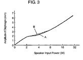
- first edge 11 and second edge 16 are of substantially symmetrical and analogous in shape so as to cancel intrinsic asymmetry. To put it concretely, first edge 11 and second edge 16 are oppositely disposed in order that their directions of protrusion are opposite. Owing to this, the two curves, A and B, in Fig. 3 showing power linearity are substantially identical. That is, the problems of non-linearity and asymmetry of the suspension can be basically solved in this way.
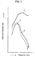
- harmonic distortions such as second and third harmonic distortion characteristics of a speaker as shown by sings D and E in Fig. 4 attributable to non-linearity and asymmetry of the suspension can be reduced, performance of the speaker can be enhanced.
- the present invention provides a speaker having small vibration distortion of the diaphragm yet having a large voice coil driving force.
- the speaker can be widely used in a variety of acoustic systems.
Landscapes
- Engineering & Computer Science (AREA)
- Physics & Mathematics (AREA)
- Acoustics & Sound (AREA)
- Signal Processing (AREA)
- Multimedia (AREA)
- Audible-Bandwidth Dynamoelectric Transducers Other Than Pickups (AREA)
- Diaphragms For Electromechanical Transducers (AREA)
Claims (7)
- Haut-parleur incluant :un châssis (9) concave ayant une ouverture sur la partie supérieure de celui-ci ;un diaphragme (10) prévu dans l'ouverture du châssis (9) avec la périphérie extérieure du diaphragme (10) étant fixée sur un bord de l'ouverture du châssis (9) par l'intermédiaire d'une première partie de bord (11) ;une bobine acoustique (12) prévue sur la surface de fond du diaphragme (10) ;un circuit magnétique (17) dans lequel au moins une partie de la bobine acoustique (12) est disposée de façon mobile dans un entrefer magnétique (14) du circuit magnétique (17) ; etun dispositif de maintien en suspension (15) ayant sa périphérie extérieure fixée sur le châssis (9) par l'intermédiaire d'une deuxième partie de bord (16) sur la surface de fond du diaphragme (10) à l'intérieur du châssis (9) ; dans lequella première et la deuxième parties de bord (11, 16) sont symétriques par rapport à un espace entre la première et la deuxième parties de bord (11, 16), la périphérie annulaire intérieure du dispositif de maintien en suspension (15) et la périphérie annulaire intérieure du diaphragme (10) sont directement ou indirectement fixées sur la bobine acoustique (12) au niveau d'une partie à l'extérieur de l'entrefer magnétique (14),caractérisé en ce quele circuit magnétique (17) a un aimant (18) prévu à l'extérieur du fond du châssis (9) avec la périphérie annulaire extérieure de l'aimant (18) s'étendant au-delà du centre de la largeur de la deuxième partie de bord (16), et l'entrefer magnétique (14) du circuit magnétique (17) est disposé poussé à l'intérieur du châssis (9) au-delà de la surface de fond du châssis (9).
- Haut-parleur selon la revendication 1 dans lequel le circuit magnétique (17) inclut :une culasse (20) ayant une saillie colonnaire formée sur une surface supérieure d'un élément en plaque ;un aimant (18) en forme d'anneau stratifié sur la culasse (20) ;une plaque (21) en forme d'anneau, la périphérie annulaire extérieure de celle-ci étant stratifiée sur l'aimant (18) et la périphérie annulaire intérieure de celle-ci étant poussée à l'intérieur du châssis (9) en même temps que la saillie colonnaire de la culasse (20), formant ainsi un entrefer magnétique (14) entre la périphérie annulaire intérieure de la plaque (21) en forme d'anneau et la périphérie annulaire extérieure de la saillie colonnaire.
- Haut-parleur selon la revendication 1 dans lequel le circuit magnétique (17) inclut :une culasse (20) ayant une saillie colonnaire formée sur la surface supérieure d'un élément en plaque ;une plaque supérieure (25) en forme de plaque stratifiée sur la saillie colonnaire de la culasse (20) ;un aimant (18) en forme d'anneau stratifié sur la culasse (20) ;une plaque (21) en forme d'anneau, la périphérie annulaire extérieure de celle-ci étant stratifiée sur l'aimant (18) et la périphérie annulaire intérieure de celle-ci étant disposée de façon à atteindre l'intérieur du châssis (9) en même temps que la saillie colonnaire de la culasse (20), formant ainsi un entrefer magnétique (14) entre la périphérie annulaire intérieure de la plaque en forme d'anneau et la périphérie annulaire extérieure de la plaque supérieure sur la saillie colonnaire.
- Haut-parleur selon la revendication 1 dans lequel une partie de marche (22) est formée sur une partie inférieure d'une surface de côté du châssis (9) pour fixer la deuxième partie de bord (16) et un évent d'aération (23) est prévu sur une partie de surface de côté plus basse que la partie de marche (22).
- Haut-parleur selon la revendication 4 dans lequel un filtre à poussières (24) est prévu dans la section d'évent d'aération.
- Haut-parleur selon la revendication 5 dans lequel le filtre à poussières (24) est prévu dans la section d'évent d'aération sur une partie extérieure du châssis (9).
- Haut-parleur selon l'une quelconque de la revendication 1 à la revendication 3 dans lequel le circuit magnétique (17) à l'aimant (18) prévu à l'extérieur du fond du châssis (9) et la périphérie annulaire extérieure de celui-ci est disposée de façon à s'étendre au moins au-delà de la deuxième partie de bord (16).
Applications Claiming Priority (2)
| Application Number | Priority Date | Filing Date | Title |
|---|---|---|---|
| JP2004248046A JP4604609B2 (ja) | 2004-08-27 | 2004-08-27 | スピーカ |
| PCT/JP2005/014069 WO2006022119A1 (fr) | 2004-08-27 | 2005-08-02 | Haut-parleur |
Publications (3)
| Publication Number | Publication Date |
|---|---|
| EP1786237A1 EP1786237A1 (fr) | 2007-05-16 |
| EP1786237A4 EP1786237A4 (fr) | 2009-11-11 |
| EP1786237B1 true EP1786237B1 (fr) | 2010-10-06 |
Family
ID=35967338
Family Applications (1)
| Application Number | Title | Priority Date | Filing Date |
|---|---|---|---|
| EP05768785A Expired - Lifetime EP1786237B1 (fr) | 2004-08-27 | 2005-08-02 | Haut-parleur |
Country Status (7)
| Country | Link |
|---|---|
| US (1) | US7532736B2 (fr) |
| EP (1) | EP1786237B1 (fr) |
| JP (1) | JP4604609B2 (fr) |
| KR (1) | KR100747938B1 (fr) |
| CN (1) | CN1843057B (fr) |
| DE (1) | DE602005024018D1 (fr) |
| WO (1) | WO2006022119A1 (fr) |
Families Citing this family (15)
| Publication number | Priority date | Publication date | Assignee | Title |
|---|---|---|---|---|
| US7225895B2 (en) * | 1998-11-30 | 2007-06-05 | Joseph Yaacoub Sahyoun | Audio speaker with wobble free voice coil movement |
| US20040188175A1 (en) * | 1998-11-30 | 2004-09-30 | Sahyoun Joseph Yaacoub | Audio speaker with wobble free voice coil movement |
| JP4867774B2 (ja) * | 2007-04-26 | 2012-02-01 | パナソニック株式会社 | スピーカ |
| KR100957539B1 (ko) * | 2008-02-29 | 2010-05-11 | 에스텍 주식회사 | 스피커 |
| US8204269B2 (en) * | 2008-08-08 | 2012-06-19 | Sahyoun Joseph Y | Low profile audio speaker with minimization of voice coil wobble, protection and cooling |
| JP5035190B2 (ja) * | 2008-09-16 | 2012-09-26 | パナソニック株式会社 | スピーカ |
| KR101085237B1 (ko) * | 2009-10-15 | 2011-11-21 | 비에취어쿠스텔 주식회사 | 슬림형 스피커 |
| KR101101991B1 (ko) * | 2009-10-15 | 2012-01-02 | 비에취어쿠스텔 주식회사 | 슬림형 스피커 |
| TW201410039A (zh) * | 2012-08-27 | 2014-03-01 | Gen Infinity Co Ltd | 揚聲器結構改良 |
| CN202949560U (zh) * | 2012-11-16 | 2013-05-22 | 瑞声声学科技(常州)有限公司 | 发声器 |
| US9485586B2 (en) | 2013-03-15 | 2016-11-01 | Jeffery K Permanian | Speaker driver |
| CN103414985B (zh) * | 2013-08-16 | 2016-05-11 | 常州博士达电子有限公司 | 微型扬声器的悬挂结构 |
| FR3014628B1 (fr) * | 2013-12-05 | 2017-04-21 | Devialet | Haut-parleur electrodynamique compact a membrane convexe |
| GB2542382A (en) | 2015-09-17 | 2017-03-22 | Gp Acoustics (Uk) Ltd | Low-profile loudspeaker |
| CN112492469B (zh) * | 2020-12-25 | 2022-03-25 | 瑞声新能源发展(常州)有限公司科教城分公司 | 发声器件 |
Family Cites Families (16)
| Publication number | Priority date | Publication date | Assignee | Title |
|---|---|---|---|---|
| FR983550A (fr) * | 1949-02-03 | 1951-06-25 | Haut-parleur perfectionné | |
| JPS5781000U (fr) * | 1980-11-05 | 1982-05-19 | ||
| JPS58161600A (ja) * | 1982-03-19 | 1983-09-26 | Matsushita Electric Ind Co Ltd | スピ−カ |
| JPH03220897A (ja) * | 1990-01-25 | 1991-09-30 | Matsushita Electric Ind Co Ltd | スピーカ |
| JP3611371B2 (ja) * | 1995-05-09 | 2005-01-19 | フオスター電機株式会社 | 防塵布及びその接着方法 |
| WO1997046046A1 (fr) * | 1996-05-31 | 1997-12-04 | Philips Electronics N.V. | Haut-parleur electrodynamique et systeme comprenant ce haut-parleur |
| JPH11275690A (ja) | 1998-03-26 | 1999-10-08 | Sony Corp | スピーカ |
| US6243479B1 (en) * | 1999-12-08 | 2001-06-05 | Lucio Proni | Loudspeaker having pole piece with integral vent bores |
| DE10120281C1 (de) * | 2001-04-25 | 2002-12-05 | Harman Audio Electronic Sys | Lautsprecher |
| WO2002102113A1 (fr) | 2001-06-11 | 2002-12-19 | Matsushita Electric Industrial Co., Ltd. | Haut parleur |
| JP3946047B2 (ja) * | 2002-01-21 | 2007-07-18 | アルパイン株式会社 | スピーカの磁気回路 |
| JP2003264891A (ja) * | 2002-03-07 | 2003-09-19 | Minebea Co Ltd | スピーカ及びその製法 |
| JP3651454B2 (ja) * | 2002-04-15 | 2005-05-25 | 松下電器産業株式会社 | スピーカ |
| JP3843901B2 (ja) * | 2002-04-15 | 2006-11-08 | 松下電器産業株式会社 | スピーカ |
| JP3991792B2 (ja) * | 2002-04-15 | 2007-10-17 | 松下電器産業株式会社 | スピーカ |
| JP3651472B2 (ja) * | 2003-10-14 | 2005-05-25 | 松下電器産業株式会社 | スピーカ |
-
2004
- 2004-08-27 JP JP2004248046A patent/JP4604609B2/ja not_active Expired - Fee Related
-
2005
- 2005-08-02 KR KR1020067004079A patent/KR100747938B1/ko not_active Expired - Fee Related
- 2005-08-02 EP EP05768785A patent/EP1786237B1/fr not_active Expired - Lifetime
- 2005-08-02 CN CN2005800009537A patent/CN1843057B/zh not_active Expired - Fee Related
- 2005-08-02 US US10/568,278 patent/US7532736B2/en not_active Expired - Fee Related
- 2005-08-02 WO PCT/JP2005/014069 patent/WO2006022119A1/fr not_active Ceased
- 2005-08-02 DE DE602005024018T patent/DE602005024018D1/de not_active Expired - Lifetime
Also Published As
| Publication number | Publication date |
|---|---|
| WO2006022119A1 (fr) | 2006-03-02 |
| CN1843057B (zh) | 2010-06-23 |
| US20060285718A1 (en) | 2006-12-21 |
| KR20060060708A (ko) | 2006-06-05 |
| JP2006067282A (ja) | 2006-03-09 |
| EP1786237A4 (fr) | 2009-11-11 |
| DE602005024018D1 (de) | 2010-11-18 |
| US7532736B2 (en) | 2009-05-12 |
| EP1786237A1 (fr) | 2007-05-16 |
| JP4604609B2 (ja) | 2011-01-05 |
| KR100747938B1 (ko) | 2007-08-08 |
| CN1843057A (zh) | 2006-10-04 |
Similar Documents
| Publication | Publication Date | Title |
|---|---|---|
| EP1881734B1 (fr) | Haut-parleur | |
| EP1515583B1 (fr) | Haut-parleur | |
| EP1786237A1 (fr) | Haut-parleur | |
| JP4735299B2 (ja) | スピーカ | |
| JP4735405B2 (ja) | スピーカ用ダンパーとそれを用いたスピーカ | |
| US8116510B2 (en) | Loudspeaker | |
| JP4569476B2 (ja) | スピーカ | |
| CN101310559B (zh) | 扬声器 | |
| CN101341791B (zh) | 扬声器 | |
| JP4618116B2 (ja) | スピーカ | |
| EP1860912A1 (fr) | Haut-parleur | |
| EP1804551B1 (fr) | Haut-parleur | |
| JP2010206558A (ja) | スピーカ | |
| JP2002281587A (ja) | スピーカ | |
| JP3991792B2 (ja) | スピーカ | |
| JP3651483B2 (ja) | スピーカ | |
| JP4735275B2 (ja) | スピーカ | |
| JP2007306204A (ja) | スピーカ | |
| JP2007194700A (ja) | スピーカ | |
| JP2007194702A (ja) | スピーカ |
Legal Events
| Date | Code | Title | Description |
|---|---|---|---|
| PUAI | Public reference made under article 153(3) epc to a published international application that has entered the european phase |
Free format text: ORIGINAL CODE: 0009012 |
|
| AK | Designated contracting states |
Kind code of ref document: A1 Designated state(s): DE FR GB IT |
|
| DAX | Request for extension of the european patent (deleted) | ||
| RBV | Designated contracting states (corrected) |
Designated state(s): DE FR GB IT |
|
| RAP1 | Party data changed (applicant data changed or rights of an application transferred) |
Owner name: PANASONIC CORPORATION |
|
| RIC1 | Information provided on ipc code assigned before grant |
Ipc: H04R 9/02 20060101AFI20090907BHEP Ipc: H04R 9/04 20060101ALI20090907BHEP |
|
| A4 | Supplementary search report drawn up and despatched |
Effective date: 20090911 |
|
| 17P | Request for examination filed |
Effective date: 20060217 |
|
| GRAP | Despatch of communication of intention to grant a patent |
Free format text: ORIGINAL CODE: EPIDOSNIGR1 |
|
| GRAS | Grant fee paid |
Free format text: ORIGINAL CODE: EPIDOSNIGR3 |
|
| GRAA | (expected) grant |
Free format text: ORIGINAL CODE: 0009210 |
|
| AK | Designated contracting states |
Kind code of ref document: B1 Designated state(s): DE FR GB IT |
|
| REG | Reference to a national code |
Ref country code: GB Ref legal event code: FG4D |
|
| REF | Corresponds to: |
Ref document number: 602005024018 Country of ref document: DE Date of ref document: 20101118 Kind code of ref document: P |
|
| PLBE | No opposition filed within time limit |
Free format text: ORIGINAL CODE: 0009261 |
|
| STAA | Information on the status of an ep patent application or granted ep patent |
Free format text: STATUS: NO OPPOSITION FILED WITHIN TIME LIMIT |
|
| 26N | No opposition filed |
Effective date: 20110707 |
|
| REG | Reference to a national code |
Ref country code: DE Ref legal event code: R097 Ref document number: 602005024018 Country of ref document: DE Effective date: 20110707 |
|
| PG25 | Lapsed in a contracting state [announced via postgrant information from national office to epo] |
Ref country code: IT Free format text: LAPSE BECAUSE OF FAILURE TO SUBMIT A TRANSLATION OF THE DESCRIPTION OR TO PAY THE FEE WITHIN THE PRESCRIBED TIME-LIMIT Effective date: 20101006 |
|
| PGFP | Annual fee paid to national office [announced via postgrant information from national office to epo] |
Ref country code: DE Payment date: 20130731 Year of fee payment: 9 |
|
| PGFP | Annual fee paid to national office [announced via postgrant information from national office to epo] |
Ref country code: FR Payment date: 20130808 Year of fee payment: 9 Ref country code: GB Payment date: 20130731 Year of fee payment: 9 |
|
| REG | Reference to a national code |
Ref country code: DE Ref legal event code: R119 Ref document number: 602005024018 Country of ref document: DE |
|
| GBPC | Gb: european patent ceased through non-payment of renewal fee |
Effective date: 20140802 |
|
| REG | Reference to a national code |
Ref country code: FR Ref legal event code: ST Effective date: 20150430 |
|
| REG | Reference to a national code |
Ref country code: DE Ref legal event code: R119 Ref document number: 602005024018 Country of ref document: DE Effective date: 20150303 |
|
| PG25 | Lapsed in a contracting state [announced via postgrant information from national office to epo] |
Ref country code: GB Free format text: LAPSE BECAUSE OF NON-PAYMENT OF DUE FEES Effective date: 20140802 Ref country code: DE Free format text: LAPSE BECAUSE OF NON-PAYMENT OF DUE FEES Effective date: 20150303 |
|
| PG25 | Lapsed in a contracting state [announced via postgrant information from national office to epo] |
Ref country code: FR Free format text: LAPSE BECAUSE OF NON-PAYMENT OF DUE FEES Effective date: 20140901 |