EP1787068B1 - Schwimmende solarplattform - Google Patents
Schwimmende solarplattform Download PDFInfo
- Publication number
- EP1787068B1 EP1787068B1 EP05785037A EP05785037A EP1787068B1 EP 1787068 B1 EP1787068 B1 EP 1787068B1 EP 05785037 A EP05785037 A EP 05785037A EP 05785037 A EP05785037 A EP 05785037A EP 1787068 B1 EP1787068 B1 EP 1787068B1
- Authority
- EP
- European Patent Office
- Prior art keywords
- trough
- floating
- rollers
- troughs
- rings
- Prior art date
- Legal status (The legal status is an assumption and is not a legal conclusion. Google has not performed a legal analysis and makes no representation as to the accuracy of the status listed.)
- Expired - Lifetime
Links
Images






Classifications
-
- F—MECHANICAL ENGINEERING; LIGHTING; HEATING; WEAPONS; BLASTING
- F24—HEATING; RANGES; VENTILATING
- F24S—SOLAR HEAT COLLECTORS; SOLAR HEAT SYSTEMS
- F24S20/00—Solar heat collectors specially adapted for particular uses or environments
- F24S20/70—Waterborne solar heat collector modules
-
- F—MECHANICAL ENGINEERING; LIGHTING; HEATING; WEAPONS; BLASTING
- F24—HEATING; RANGES; VENTILATING
- F24S—SOLAR HEAT COLLECTORS; SOLAR HEAT SYSTEMS
- F24S30/00—Arrangements for moving or orienting solar heat collector modules
- F24S30/40—Arrangements for moving or orienting solar heat collector modules for rotary movement
- F24S30/42—Arrangements for moving or orienting solar heat collector modules for rotary movement with only one rotation axis
- F24S30/422—Vertical axis
-
- Y—GENERAL TAGGING OF NEW TECHNOLOGICAL DEVELOPMENTS; GENERAL TAGGING OF CROSS-SECTIONAL TECHNOLOGIES SPANNING OVER SEVERAL SECTIONS OF THE IPC; TECHNICAL SUBJECTS COVERED BY FORMER USPC CROSS-REFERENCE ART COLLECTIONS [XRACs] AND DIGESTS
- Y02—TECHNOLOGIES OR APPLICATIONS FOR MITIGATION OR ADAPTATION AGAINST CLIMATE CHANGE
- Y02E—REDUCTION OF GREENHOUSE GAS [GHG] EMISSIONS, RELATED TO ENERGY GENERATION, TRANSMISSION OR DISTRIBUTION
- Y02E10/00—Energy generation through renewable energy sources
- Y02E10/40—Solar thermal energy, e.g. solar towers
- Y02E10/47—Mountings or tracking
Definitions
- WO 03/032404 and WO 03/034506 are known photovoltaic Krefttechnike containing a number of concentrators, which are summarized in circular platforms, following the sun pivot about the vertical axis.
- An advantageous solution provides a floating ring surrounding the concentrators. The floating ring lies between three arranged around the ring rollers and is thus fixed in position.
- the floating ring is fished between three rollers, the rollers are rotatably mounted on a pedestal, for example made of concrete, advantageously two rollers roll on the inside of the ring, while the third roller engages the outside of the ring. It is possible for an outboard attacking roll to roll off simultaneously on three platforms, creating a platform triad.
- the underside of the base is so smooth and even that it is possible to move the entire unit of rings and base.
- the invention provides for externally acting rollers, which are pressed by suitable guides against the circumference of a ring.
- One of the inside or outside of the ring lying rollers is driven and transmits the torque the floating ring.
- this is an externally attacking role, which is mounted above the water level, that is surrounded by air used.
- the invention in order for the three platforms of a triad to be able to be further rotated by a certain angle in synchrony, provides a chain, e.g. mounted on the ring and in which engages a ring gear. In place of gears may also occur an electronically controlled ring, which has optical or magnetic markings instead of teeth.
- the invention provides a ring of signalers on the platform. These can be, for example, reflective plates that reflect the light beam of a sensor.
- the speed of rotation of the platform is calculated by means of a processor. If this exceeds the setpoint value, the speed of the geared motor is reduced somewhat; if it is below the setpoint, the setpoint is reached by acceleration of the motor.
- an optical counting of the co-rotating signal generator can also be a magnetic sensor, which registers the magnetic field change of ferromagnetic or permanent magnetic signal generators. The reflection of acoustic signals can also be used for comparison with nominal values.
- the invention provides ball bearing-carrying strand-like partitions, which are arranged between the troughs.
- the platforms have no mechanical structural element in the center of the platform. There, however, the discharge of the current is carried out by two highly flexible lines, which allow the daily rotation of the platform. To control the speed of rotation, a sun finder can also be used.
- the drive of the floating ring can be done in successive pulses.
- the angle of incidence experiences small deviations from the respective desired value.
- the invention compensates for these deviations by focusing the focus of the concentrator lens not directly at the photovoltaic cell, but at the sun-facing surface of a glass body which mixes the beams by internal reflection and causes them to be uniformly distributed to one with the glass body Impact connected photocell.
- This arrangement causes, even if the incident direction of the beam cone from the desired direction by significant angular amounts of e.g. ⁇ 2 °, but the entire radiation current reaches the photocell.
- the size of the achievable tolerance is determined by the ratio of the size of the sun-facing surface of the glass body to the diameter of the focal surface.
- This arrangement also compensates for errors that occur in the implementation of the pulses in mechanical distances in the transmission structure, so that the tolerances may be far greater than in sun-related transmissions according to the prior art. In any case, this leads to a considerable reduction in the manufacturing costs of the transmission.
- the invention thus shows a way how high precision, which causes high costs, can be avoided.
- the invention decouples the alignment of the radiation-absorbing components from the radiation-converting components by the concentration of the concentrating device leads to the smallest possible focal area, which is directed to the glass body, the entrance surface for the extremely concentrated radiation current by a multiple, for example by twenty times is larger than the area of the focal region and that the rays entering the glass body are directed to an energy converter, for example a photocell, which splits the radiation current into a heat flow and an electron flow.
- an energy converter for example a photocell
- the invention permits a displacement of this focal region in a horizontal and perpendicular direction until the focal region reaches the edge of the entry surface.
- the beam of the concentrated cone of radiation which is displaceable perpendicularly to the sun's rays, may therefore deviate from the direction of the sun's rays by an angle which is greater the shorter the focal length of the cone of rays relative to the extension of the entrance surface into the glass body, without thereby energy of the radiation current lost for the photocell. This means that even with great tolerance in the mechanical tracking device, a loss-free function guaranteeing accuracy is always achieved, so that the entire concentrated radiation current is utilized.
- the floating, circular rings are crossed by partitions that run on sinews. At a short distance from each other, these partitions contain ball bearings, are mounted by attached to troughs stub shafts through which the troughs are pivotable. Perpendicular to these partitions run steel cables that are so taut that the circular shape of the floating ring is guaranteed.
- the troughs are shaped so that the area projecting into the body of water generates an exactly vertical buoyancy force at each angular position, so that no torque is generated.
- the troughs themselves are tapered, making them stackable, significantly reducing the cost of transport between the manufacturing site and the site.
- a buoyancy aid in the form of a cylinder is attached with nikabismeförmigem cross section, which prevents buoyancy-related torques.
- the troughs are covered with lenses made of transparent plastic. Within a circumscribed circle, the lenses are cambered, the cross section through the lens runs there on a spherical surface whose spherical axis passes through the intersection of the diagonal of the circumscribed square.
- the ball-shaped area has refractive grooves.
- the four edge regions have a groove, which generates an internal reflection for beam deflection.
- the longitudinal edges of the troughs edges of the lenses are bent by a small amount, whereby they can be slidably connected to the walls of the troughs by a small amount, so that they take over the function of structural elements.
- the troughs each consist of an open trough having conical walls, whereby the possibility of stacking is given.
- the trough floats in the water layer and is pivotable about its horizontal axis.
- To avoid the emergence of a torque buoyancy aid is attached to the sun-facing wall, which continues the rounding of the bottom area.
- the weight of the lens is compensated by a arranged in the lower part of the trough balance weight.
- the control of the azimuth speed and the function of the elevation gear can be done by recorded astronomical data.
- the invention prefers a sun tracking unit so that azimuth and elevation control is done depending on the course of the sun.
- the invention prevents this by an auxiliary drive, which takes over the continuation of the azimuth following migration, so the rotation of the platform when the sun-guided hike.
- the suspension of the power supply of the geared motor applies, for example, by a cloud as a signal for the activation of the auxiliary drive.
- the invention provides a thin layer of high boiling liquid which is lighter than water which also prevents the formation of mosquito larvae.
- the invention provides that the body of water may contain an alcohol, e.g. glycol; is added.
- an alcohol e.g. glycol
- Another solution for preventing evaporation, but also as protection against night frosts is that between successive troughs a flexible film is arranged, which covers the water surface. In areas with risk of frost, a heat-insulating film is provided.
- FIG. 1 shows the basic structure of a triad.
- the column 2 In the center of the concrete base 1 is the column 2, on which two rollers 12 are arranged for each floating ring. Trained as a drive wheel 3, which drives the three platforms 5, 6 and 7, lies in the center of the gusset area 4. Troughs 9 are arranged pivotable about its horizontal axis between the partitions 8. Between the troughs 9 extend metal wires 11, through which the circular shape of the floating ring 10 is ensured. The platforms are surrounded by floating rings 10. In the evening, the lenses are cleaned. For this purpose, a spray nozzle is arranged on the central column 2, through which a pump arranged in the base flows filtered water. The platform rotates 180 degrees.
- FIG. 2 shows a larger footprint with triads.
- the distance 20 between the troughs is sized so that a person can get anywhere.
- a gusset region 21 remains.
- FIG. 3 schematically shows a vertical section through the gusset area.
- One of the three platforms 30 is shown in section.
- the pillar 32 In the center of the gusset is the pillar 32, on which the roller formed as a drive roller 33 is mounted.
- the drive takes place via the underwater geared motor 31.
- the circumference of the drive wheel 33 and the circumference of the platform 30 are toothed.
- Two of the rollers 34 contact the floating ring 36 at the inner diameter 35, so that the floating ring 36 is fixed at a distance from the column 32 and the periphery.
- a pivotable spray nozzle 37 At the upper end of the column 32, which cleans the lenses in the evening with filtered water.
- FIG. 4 shows the top view of a triad with the column 42nd
- FIG. 5 shows the same triad from the bottom, where the concrete base 51 is located, the bottom is flat and smooth. The entire unit can thereby be moved to the desired position on the foil that separates the body of water from the ground, with the platforms carried by the water. In each case in the center of the platform, two highly flexible cables 52 exit, through which the current is fed into the connecting line 53.
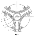
- FIG. 6 shows the transmission of torque via a designed as a central gear 61 roller.
- a roller chain 63 is fixed by extending elongated chain pins 64 into holes of the floating ring 62.
- the stationary rollers 65 fixed to the concrete base.
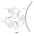
- FIG. 7 shows a torque transmitting construction with three trained as sprockets 71 roles. Each of these wheels 71 is mounted on a rocker 72. The three rockers are pivotally mounted on a central disc 74 and are urged against the chain 73 by tension springs 75.
- FIG. 8 shows a construction in which the distance of the three platforms from each other by rollers 85 is formed. Instead of lying in the water layer rollers here prevent the rollers 85 emigration of the three floating rings.
- the advantage of this solution is that all mechanical elements are above the water layer. The drive takes place via a geared motor, which drives one of the three rollers designed as sprockets 81, which determine the distance between the three platforms.
- FIG. 9 shows the cross section through a trough with the trough 90, the buoyant body 91, the lens 92 and the energy converter 93.
- the tufts 94 generates the focal point 95 on the entrance surface of the secondary optics 96.
- the housing of the energy converter 93 terminates with the axis of secondary optics an acute Angle.
- the trough is pivotable about the horizontal axis 100.
- the level line 99 marks the water surface at 90 degrees elevation.
- the submerged in the water area 101 forms together with the buoyancy body 91 always a constant buoyancy, which corresponds to the weight of the trough.
- the lens 92 is square and has a inscribed circular area extending on a spherical portion 104.
- FIG. 10 shows the end of a trough that holds up to 10 lenses and energy converters.
- the end wall 111 extends obliquely to the walls of the trough, so that they can be stacked without buoyancy aid 91 a.
- the hollow stub axle 112 is arranged, lead through the electrical lines.
- the bottom of the sheet metal wall 113 has an expression 114, in which the energy converter 93 is screwed.
- FIG. 11 shows the pivotal position of a trough 115 at 90 degrees sun altitude.
- the trough 116 shows the pivoting by 28 degrees.
- the trough 117 is shadowed by the adjacent trough by a negligible percentage of the entrance surface 118.
- the trough 119 shows the entry situation in the morning at the threshold angle of 63 degrees between the irradiation 120 and the vertical 121, where 46% of the lens lie in the shadow of the neighboring trough 119a.
- the trough experiences this tilt but only for a few minutes.
- the incoming radiation current is spread evenly over the surface of the photocell.
- FIG. 12 shows a cross section from which it can be seen that the trough body can be stacked for transport, wherein the distance 122 is kept as small as possible.
- FIG. 13 shows the partition wall 130, whose lower portion 131 is hollow and so far into the water line 99 that the partition is supported by the buoyancy.
- breakthroughs are arranged through which passes a hollow shaft 133 which is aligned with the stub axles 112, and which is mounted in a plastic ball bearing 132.
- holders 134 and 135 are connected to each other by screws 136, which pass through openings on the partition wall.
- FIGS. 14 and 15 show the area of the breakthrough of the wall 130 increases.
- the holder elements 134 and 135 have, as shown in Figure 15, conical sleeves 150, into which conical pins 140, which are fixed to the stub axles 112, protrude. Slots 151 are disposed in the partition wall 130, through which the bolts 136b protrude, so that a torque is transmitted around the hollow shaft 133a.
- FIG. 16 shows a bridge 160. Four to five lenses form a lens unit. Between two lens units of the web 160 is arranged, the like FIG. 17 can be seen, tabs 161, 161a, on which rests the free end of the lens units.
- FIG. 17 are the plate tips 162 and 162a (off Fig. 16 Recognizable) shown by a rubber bait, which prevents the ingress of rainwater into the trough, is held in its position.
- FIG. 18 shows the secondary optics 181, which has a distance from the concentrator lens 182, which corresponds exactly to the focal length. For the sake of illustration, a distance is left between the focal point 183 and the surface 184 of the secondary optics 181 facing it, shown from the inside.
- the concentrator lens 182 concentrates the sun irradiation on about 8000 suns, the focal area 183 is only a few millimeters in size.
- the lateral walls 185 of the secondary optics reflect the radiation current 186, which at the end impinges on the photocell 187, which is optically connected to the secondary optics.
- the focal point 183 travels on the surface area 184 which is much larger in area compared to the focal area, so that angle deviations within a tolerance interval of eg ⁇ 2 degrees do not lead to a reduction in power, while all known systems with biaxial solar tracking only allow an interval of ⁇ 0.1 degrees.
- the large tolerance interval allows a mechanical design without costly precision parts.
- FIG. 19 shows the juxtaposition of a prior art concentrator B and a concentrator A.
- the photocell 191 is above the focal plane 193.
- An angular deviation between the sun's rays 195 and the lens 192 causes rays to pass the photocell 191 and at the same time the photocell remains unexposed over a region 194, resulting in thermal stresses.
- Fig.19B shows the secondary optics 196 according to the invention and the focal region 197, which has emigrated by a considerable amount from the central beam 198. The total radiant energy enters secondary optics 196 and passes, as in FIG Fig. 18 shown on the photocell 199.
- FIG. 20 shows a flexible film 201, which extends over the entire length of the diameter of the floating ring.
- heat pipes 202 which transfer the heat via ribs 203 to the outside air.
- the heat pipe conducts heat only from the lower region 204 to the ribs 203, the reverse direction leads to no heat transfer, since the filling of the heat pipe freezes, so that negative temperatures are not passed into the water.
- FIG. 21 shows an arrangement in which the film 211 is extremely folded to increase the water surface to increase the heat transfer between the water and the outside air.
- FIG. 22 shows a floating element 221 that seals the space between two troughs.
Landscapes
- Engineering & Computer Science (AREA)
- Chemical & Material Sciences (AREA)
- Mechanical Engineering (AREA)
- Sustainable Development (AREA)
- Sustainable Energy (AREA)
- Thermal Sciences (AREA)
- Physics & Mathematics (AREA)
- Combustion & Propulsion (AREA)
- Life Sciences & Earth Sciences (AREA)
- General Engineering & Computer Science (AREA)
- Photovoltaic Devices (AREA)
- Road Signs Or Road Markings (AREA)
- Road Paving Structures (AREA)
- Liquid Crystal Substances (AREA)
- Cleaning By Liquid Or Steam (AREA)
Description
- Aus
WO 03/032404 WO 03/034506 - Der Nachteil dieser Methode besteht darin, dass die drei Rollen im Erdreich fixiert sein müssen, was drei Durchbrüche in der Schicht, z.B. einer Kunststoff-Folie, die den Wasserkörper vom Erdboden trennt, erfordert. Diese Durchbrüche sind nur seiten für längere Zeit zuverlässig abzudichten, sie führen oft zu laufendem Wasserverlust. Außerdem ist durch drei derartige Rollen der Standort der Plattform bleibend festgelegt.
- Die Erfindung zeigt eine Lösung, die diese Nachteile nicht aufweist.
Gemäss der Erfindung wird der schwimmende Ring zwischen drei Rollen gefengen, Die Rollen sind auf einem Sockel z.B. aus Beton drehbar befestigt, wobei vorteilhaft zwei Rollen an der Innenseite des Ringes abrollen, während die dritte Rolle an der Außenseite des Ringes angreift. Es ist möglich, dass eine außenseitig angreifende Rolle gleichzeitig an drei Plattformen abrollt, wodurch ein Plattform-Triad entsteht. Die Unterseite des Sockels ist so glatt und eben, dass ein Verschieben der gesamten Einheit von Ringen und Sockel möglich ist. - Damit Ringe von vielen Metern Durchmesser dem geometrischen Kreis exakt folgen, sieht die Erfindung von außen angreifende Rollen vor, die durch geeignete Führungen gegen den Umfang eines Ringes gepresst werden. Eine der innen oder außen am Ring liegenden Rollen wird angetrieben und überträgt das Drehmoment auf den schwimmenden Ring. Vorteilhaft wird hierzu eine von außen angreifende Rolle, die oberhalb des Wasserspiegels angebracht wird, also von Luft umgeben ist, eingesetzt.
- Damit die drei Plattformen eines Triads genau synchron um einen bestimmten Winkel weiter gedreht werden können, sieht die Erfindung in einer Ausführungsform eine Kette vor, die z.B. auf dem Ring montiert ist und in die ein Zahnkranz eingreift. An die Stelle von Zahnrädern kann auch ein elektronisch gesteuerter Ring treten, der an Stelle von Zähnen optische oder magnetische Markierungen aufweist.
- An Stelle einer Steuerung durch die Sonnenbewegung werden gemäss der vorliegenden Erfindung vorzugsweise berechnete Signale eingesetzt. Die Umsetzung dieser Signale auf die Drehung der Plattform würde bei Reibradantrieb aber an der schlupfbehafteten Übertragung des Drehmomentes vom Reibrad auf die Plattform scheitern. Deshalb ist eine digitale Übertragung zwischen dem Getriebe und der Plattform einzuschalten, wie sie durch Zahnradübertragung möglich ist. Falls die Plattform nicht mit Zähnen versehen werden kann, sieht die Erfindung einen Kranz von Signalgebern auf der Plattform vor. Diese können zum Beispiel reflektierende Plättchen sein, die den Lichtstrahl eines Sensors reflektieren. Bei dieser Methode wird über einen Prozessor die Drehgeschwindigkeit der Plattform errechnet. Übersteigt diese den Sollwert, so wird die Drehzahl des Getriebemotors etwas herabgesetzt, liegt diese unter dem Sollwert, so erfolgt die Erreichung des Sollwertes durch Beschleunigung des Motors.
An die Stelle einer optischen Zählung der mitumlaufenden Signalgeber kann auch ein magnetischer Sensor treten, der die Magnetfeldänderung von ferro- oder permanentmagnetischen Signalgebern registriert. Auch kann die Reflektion akustischer Signale zum Vergleich mit Sollwerten eingesetzt werden. - Für die Fixierung der die Konzentratoren aufnehmenden Tröge innerhalb des schwimmenden Ringes, sieht die Erfindung Kugellager-tragende strangförmige Trennwände vor, die zwischen den Trögen angeordnet sind. Die Plattformen weisen kein mechanisches Strukturelement im Zentrum der Plattform auf. Dort aber erfolgt die Ausleitung des Stromes durch zwei höchstflexible Leitungen, die die tägliche Drehung der Plattform gestatten. Zur Steuerung der Umlaufgeschwindigkeit kann auch ein Sonnenfinder eingesetzt werden.
- Es ist vorteilhaft, wenn der Antrieb des schwimmenden Ringes in zeitlich aufeinanderfolgenden Impulsen erfolgen kann. In Abhängigkeit vom zeitlichen Abstand der Impulse erfährt der Auftreffwinkel geringe Abweichungen vom jeweiligen Sollwert. Die Erfindung gleicht diese Abweichungen aus, indem der Fokus der Konzentratorlinse nicht direkt auf die photovoltaische Zelle gerichtet ist, sondern auf die zur Sonne zeigende Fläche eines Glaskörpers, der die Strahlen durch innere Reflexion mischt und bewirkt, dass diese gleichmäßig verteilt auf eine mit dem Glaskörper verbundene Photozelle auftreffen. Diese Anordnung bewirkt, dass auch dann, wenn die Auftreffrichtung des Strahlenkegels von der Soll-Richtung um erhebliche Winkelbeträge von z.B. ± 2º abweicht, dennoch der gesamte Strahlungsstrom zur Photozelle gelangt. Die Größe der realisierbaren Toleranz wird durch das Verhältnis der Größe der zur Sonne weisenden Fläche des Glaskörpers zum Durchmesser der Fokalfläche bestimmt. Diese Anordnung kompensiert auch Fehler, die bei der Umsetzung der Impulse in mechanische Abstände im Getriebeaufbau entstehen, so dass die Toleranzen weit größer sein dürfen als bei sonnenfolgenden Getrieben nach dem Stand der Technik. Dies führt in jedem Falle zu einer erheblichen Verbilligung der Herstellungskosten der Getriebe.
- Konzentrierende Solarenergiewandler mit mechanischer Nachführung zur Sonne führen zu hohen Wirkungsgraden, benötigen aber bisher Nachführvorrichtungen von der Präzision der Nachführvorrichtungen von Planetarien.
- Die Erfindung zeigt also einen Weg, wie hohe Präzision, die hohe Kosten verursacht, vermeidbar ist. Dazu entkoppelt die Erfindung die Ausrichtung der strahlungsaufnehmenden Komponenten von den strahlungsumwandelnden Komponenten, indem die Konzentration der konzentrierenden Vorrichtung zu einem möglichst kleinen Fokalbereich führt, der auf den Glaskörper gerichtet ist, dessen Eintrittsfläche für den extrem konzentrierten Strahlungsstrom um ein Mehrfaches, zum Beispiel um das zwanzigfache größer ist als die Fläche des Fokalbereiches und dass die in den Glaskörper eintretenden Strahlen auf einen Energiewandler, zum Beispiel eine Photozelle geleitet werden, der den Strahlungsstrom in einen Wärmestrom und einen Elektronenstrom aufteilt. Wenn die Sollposition des Fokalbereiches auf der Eintrittsfläche des Glaskörpers im Zentrum dieser Eintrittsfläche liegt, so erlaubt die Erfindung eine Verschiebung dieses Fokalbereiches in horizontaler und rechtwinklig dazu verlaufender Richtung bis der Fokalbereich den Rand der Eintrittsfläche erreicht. Der senkrecht zu den Sonnenstrahlen verschiebliche Strahl des konzentrierten Strahlungskegels darf also um einen Winkelbetrag, der umso größer ist je kürzer die Fokallänge des Strahlenkegels im Verhältnis zur Erstreckung der Eintrittsfläche in den Glaskörper ist, von der Richtung der Sonnenstrahlen abweichen, ohne dass dadurch Energie des Strahlungsstromes für die Photozelle verloren geht. Das bedeutet, dass auch bei großer Toleranz in der mechanischen Nachführvorrichtung immer eine die verlustfrei Funktion garantierende Genauigkeit erreicht wird, dass also der gesamte konzentrierte Strahlungsstrom genutzt wird.
- Die schwimmenden, kreisförmigen Ringe sind von Trennwänden durchzogen, die auf Sehnen verlaufen. In kurzem Abstand voneinander enthalten diese Trennwände Kugellager, durch die an Trögen befestigte Achsstummel gelagert werden, durch die die Tröge schwenkbar sind. Senkrecht zu diesen Trennwänden verlaufen Stahlseile, die so gespannt sind, dass die Kreisform des schwimmenden Ringes gewährleistet ist.
- Die Tröge sind so geformt, dass der in den Wasserkörper hineinragende Bereich bei jeder Winkelstellung eine genau vertikale Auftriebskraft erzeugt, so dass kein Drehmoment entsteht. Die Tröge selbst sind konisch ausgebildet, wodurch sie stapelbar werden, was die Transportkosten zwischen dem Herstellungsort und dem Aufstellungsort erheblich herabsetzt. An der zum Wasserkörper weisenden Seite jedes Troges ist eine Auftriebshilfe in Form eines Zylinders mit kreisabschnittförmigem Querschnitt befestigt, die auftriebsbedingte Drehmomente verhindert. Die Tröge sind mit Linsen aus transparentem Kunststoff abgedeckt. Innerhalb eines umschriebenen Kreises sind die Linsen bombiert, der Querschnitt durch die Linse verläuft dort auf einer Kugelfläche, deren Kugelachse den Schnittpunkt der Diagonalen des umschriebenen Quadrates durchsetzt. Der kugelausschnittförmige Bereich trägt refraktive Rillen. Die vier Randbereiche weisen eine Rillung auf, die zur Strahlumlenkung eine innere Reflektion erzeugen.
- Die in Längsrichtung der Tröge verlaufenden Kanten der Linsen sind um einen geringen Betrag abgebogen, wodurch sie mit den Wandungen der Tröge um einen geringen Betrag verschiebbar verbunden werden können, so dass sie die Funktion von Strukturelementen übernehmen.
- Die Tröge bestehen jeweils aus einer offenen Wanne, die konisch verlaufende Wandungen aufweist, wodurch die Möglichkeit des Stapelns gegeben ist. Der Trog schwimmt in der Wasserschicht und ist um seine horizontale Achse schwenkbar. Zur Vermeidung der Entstehung eines Drehmomentes ist an der zur Sonne weisenden Wandung eine Auftriebshilfe befestigt, die die Rundung des Bodenbereiches fortsetzt. Hierdurch wird der Trog durch Auftrieb getragen, und ein Drehmoment um die Achse vermieden. Das Gewicht der Linse wird durch ein im unteren Bereich des Troges angeordnetes Ausgleichsgewicht kompensiert.
- Die Steuerung der azimutahlen Geschwindigkeit und die Funktion des Elevationsgetriebes kann durch aufgezeichnete astronomische Daten erfolgen. Die Erfindung aber zieht eine Sonnennachführungseinheit vor, so dass Azimuth und Elevationssteuerung in Abhängigkeit vom Lauf der Sonne erfolgt. Es hat sich aber gezeigt, dass bei Abblockung der Sonnenstrahlen z.B. durch eine Wolke die Gefahr besteht, dass bei Beendigung der Abblockung der Fokus in die neue Position wandert und auf diesem Wege Schaden z.B. durch Verbrennen der Kabelisolation anrichten kann. Die Erfindung verhindert dies durch einen Hilfsantrieb, der bei Aussetzen der sonnengeführten Wanderung die Fortsetzung der dem Azimut folgenden Wanderung , also die Drehung der Plattform übernimmt. Hierbei gilt das Aussetzen der Speisung des Getriebemotors zum Beispiel durch eine Wolke als Signal für die Einschaltung des Hilfsantriebes.
- Zur Verhinderung von Verdunstung der Wasserschicht sieht die Erfindung eine dünne Schicht einer hochsiedenden Flüssigkeit vor, die leichter ist als Wasser, die auch die Bildung von Mückenlarven verhindert. In Regionen, in denen Frost zu erwarten ist, sieht die Erfindung vor, dass dem Wasserkörper ein Alkohol, z.B. Glykol; beigemischt wird. Eine andere Lösung zur Verdunstungsverhinderung, aber auch als Schutz gegen Nachtfröste besteht darin, dass zwischen aufeinanderfolgenden Trögen eine flexible Folie angeordnet ist, die die Wasseroberfläche abdeckt. In Gegenden mit Frostgefahr ist eine wärmeisolierende Folie vorgesehen.
- Die Erfindung soll anhand von Figuren beschrieben weren:
- Fig. 1
- zeigt den Grundaufbau eines Triads
- Fig. 2
- zeigt das Zusammenschachteln von Triads
- Fig. 3
- zeigt schematisiert einen Vertikalschnitt durch den Zwickelbereich
- Fig. 4
- zeigt die Draufsicht auf ein Triad
- Fig. 5
- zeigt ein Triad von unten gesehen
- Fig. 6
- zeigt einen Antrieb mit einem Zentralrad und Rollenketten
- Fig. 7
- zeigt eine Übertragungsanordnung mit Kettenrädern
- Fig. 8
- zeigt eine Anordnung der treibenden und führenden Rollen
- Fig. 9
- zeigt den Trog und die Linsen mit Auftriebshilfe
- Fig. 10
- zeigt die Endwand eines Troges
- Fig. 11
- zeigt die Bestrahlung bei unterschiedlicher Elevation
- Fig. 12
- zeigt die Stapelung von Trögen
- Fig. 13
- zeigt die Trennwand und die Kupplungselemente
- Fig. 14
- zeigt die Kupplungselemente und das Kugellager
- Fig. 15
- zeigt die Durchbrüche durch die Trennwand
- Fig. 16
- zeigt den Steg unter benachbarten Linsen
- Fig. 17
- zeigt den Steg und die Vorsprünge
- Fig. 18
- zeigt die Sekundäroptik
- Fig. 19
- zeigt den Vergleich zum Stand der Technik
- Fig. 20
- zeigt die Abdeckung des Wasserkörpers mit Wärmeausleitung
- Fig. 21
- zeigt die gefaltete Abdeckung
- Fig. 22
- zeigt einen schwimmenden Abdeckkörper
-
Figur 1 zeigt den Grundaufbau eines Triads. Im Zentrum des Betonsockels 1 befindet sich die Säule 2, auf der für jeden schwimmenden Ring zwei Rollen 12 angeordnet sind. Das als Treibrad 3 ausgebildete Rolle, die die drei Plattformen 5, 6 und 7 antreibt, liegt im Mittelpunkt des Zwickelbereiches 4. Zwischen den Trennwänden 8 sind Tröge 9 um ihre Horizontalachse schwenkbar angeordnet. Zwischen den Trögen 9 verlaufen Metalldrähte 11, durch die die Kreisform des schwimmenden Ringes 10 gewährleistet ist. Die Plattformen sind von schwimmenden Ringen 10 umgeben. Am Abend werden die Linsen gereinigt. Dazu ist auf der zentralen Säule 2 eine Sprühdüse angeordnet, durch die eine im Sockel angeordnete Pumpe gefiltertes Wasser ausströmt. Dabei rotiert die Plattform um 180 Grad. -
Figur 2 zeigt eine größere Grundfläche mit Triads. Der Abstand 20 zwischen den Trögen ist so bemessen, dass eine Person überall hingelangen kann. Zwischen den drei Ringen verbleibt ein Zwickelbereich 21. -
Figur 3 zeigt schematisiert einen Vertikalschnitt durch den Zwickelbereich. Eine der drei Plattformen 30 ist im Schnitt gezeigt. Im Mittelpunkt des Zwickels liegt die Säule 32, auf der die als Treibrad 33 ausgebildete Rolle gelagert ist. Der Antrieb erfolgt über den Unterwasser- Getriebemotor 31. Der Umfang des Treibrades 33 und der Umfang der Plattform 30 sind gezahnt. Zwei der Rollen 34 berühren den schwimmenden Ring 36 am inneren Durchmesser 35, so dass der schwimmende Ring 36 im Abstand zur Säule 32 und zum Umfang hin fixiert ist. Am oberen Ende der Säule 32 ist eine schwenkbare Spritzdüse 37 angeordnet, die abends die Linsen mit gefiltertem Wasser reinigt. -
Figur 4 zeigt die Draufsicht auf ein Triad mit der Säule 42. -
Figur 5 zeigt das gleiche Triad von der Unterseite, wo sich der Betonsockel 51 befindet, dessen Unterseite eben und glatt ist. Die gesamte Einheit kann dadurch auf der Folie, die den Wasserkörper vom Boden trennt, in die gewünschte Position verschoben werden, wobei die Plattformen vom Wasser getragen werden. Jeweils im Zentrum der Plattform treten zwei hochflexible Kabel 52 aus, durch die der Strom in die Verbindungsleitung 53 eingespeist wird. -
Figur 6 zeigt die Übertragung des Drehmomentes über ein als zentrale Zahnrad 61 ausgebildete Rolle. Auf jedem der schwimmenden Ringe 62 ist eine Rollenkette 63 dadurch befestigt, dass verlängerte Kettenbolzen 64 in Bohrungen des schwimmenden Ringes 62 hineinragen. An der Innenseite der schwimmenden Ringe 62 greifen die stationären, am Betonsockel befestigten Rollen 65 an. -
Figur 7 zeigt eine Drehmoment übertragende Konstruktion mit drei als Kettenrädern 71 ausgebildete Rollen. Jedes dieser Räder 71 ist auf einer Wippe 72 gelagert. Die drei Wippen sind an einer zentralen Scheibe 74 schwenkbar befestigt und werden durch Zugfedern 75 gegen die Kette 73 gedrückt. -
Figur 8 zeigt eine Konstruktion bei der die Distanz der drei Plattformen voneinander durch Rollen 85 gebildet wird. Anstelle der in der Wasserschicht liegenden Rollen verhindern hier die Rollen 85 ein Auswandern der drei schwimmenden Ringe. Der Vorteil dieser Lösung liegt darin, dass alle mechanischen Elemente oberhalb der Wasserschicht liegen. Der Antrieb erfolgt über einen Getriebemotor, der eine der drei als Kettenräder 81 ausgebildeten Rollen antreibt, die den Abstand zwischen den drei Plattformen bestimmen. -
Figur 9 zeigt den Querschnitt durch einen Trog mit der Wanne 90, dem Auftriebskörper 91, der Linse 92 und dem Energiewandler 93. Das Strahlenbüschel 94 erzeugt den Fokalpunkt 95 auf der Eintrittsfläche der Sekundäroptik 96. Das Gehäuse des Energiewandlers 93 schließt mit der Achse der Sekundäroptik einen spitzen Winkel ein. Im Zusammenwirken mit dem Fuß 97 erreicht der Energiewandler 93 auch noch bei extremer Schräglage relativ zur Wasseroberfläche 98 den Wasserkörper, um den bei dem Extremwinkel von 26 Grad anfallenden relativ geringen Abwärmestrom in den Wasserkörper einzuleiten. Der Trog ist um die horizontale Achse 100 schwenkbar. Die Niveaulinie 99 kennzeichnet die Wasseroberfläche bei 90 Grad Elevation. Der ins Wasser eintauchende Bereich 101 bildet zusammen mit dem Auftriebskörper 91 einen stets gleichbleibenden Auftrieb, der dem Gewicht des Troges entspricht. Durch die kreiszylindrischen Bereiche 91 und 102 ändert sich der Abstand zwischen der Wasseroberfläche und der Achse 100 nicht, so dass der Achsstummel 103 weder eine Höhenverschiebung noch ein hydraulisch bedingtes Drehmoment erfährt. Die Linse 92 ist quadratisch und hat eine einbeschriebene Kreisfläche, die auf einem Kugelabschnitt 104 verläuft. -
Figur 10 zeigt den Endbereich eines Troges, der bis zu 10 Linsen und Energiewandler aufnimmt. Die Endwandung 111 verläuft schräg zu den Wandungen der Trogwanne, sodass diese ohne Auftriebshilfe 91 a gestapelt werden können. An der Endplatte 111 ist der hohle Achsstummel 112 angeordnet, durch den elektrische Leitungen führen. Der Boden der Blechwandung 113 weist eine Ausprägung 114 auf, in die der Energiewandler 93 eingeschraubt wird. -
Figur 11 zeigt die Schwenkposition eines Troges 115 bei 90 Grad Sonnenhöhe. Der Trog 116 zeigt die Schwenkung um 28 Grad. Der Trog 117 ist durch den Nachbartrog um einen verschwindend geringen Prozentsatz der Eintrittsfläche 118 beschattet. Der Trog 119 zeigt die Eintrittssituation am Morgen beim Grenzwinkel von 63 Grad zwischen der Einstrahlung 120 und der Vertikalen 121, wo 46% der Linse im Schatten des Nachbartroges 119a liegen. Der Trog erfährt diese Schräglage aber nur für wenige Minuten. Durch eine Sekundäroptik wird der eintretende Strahlungsstrom gleichmäßig über die Fläche der Photozelle ausgebreitet. -
Figur 12 zeigt einen Querschnitt, aus dem ersichtlich ist, dass die Trogkörper für den Transport gestapelt werden können, wobei der Abstand 122 möglichst klein gehalten wird. -
Figur 13 zeigt die Trennwand 130, deren unterer Bereich 131 hohl ist und in die Wasserlinie 99 so weit hineinragt, dass die Trennwand vom Auftrieb getragen wird. Über die Länge der Trennwand sind Durchbrüche angeordnet, durch die eine Hohlachse 133 dringt, die mit den Achsstummeln 112 fluchtet, und die in einem Kunststoff-Kugellager 132 gelagert ist. An den beiden Seiten der Trennwand 130 sind Halter 134 und 135 durch Schrauben 136 miteinander verbunden, die Durchbrüche an der Trennwand durchsetzen. -
Figur 14 und 15 zeigen den Bereich des Durchbruches der Wandung 130 vergrößert. Die Halterelemente 134 und 135 weisen, wie aus Zeichnung 15 ersichtlich, konische Hülsen 150 auf, in die konische Stifte 140, die an den Achsstummeln 112 befestigt sind, hineinragen. In der Trennwand 130 sind Schlitze 151 angeordnet, durch die die Schrauben 136b hindurchragen, so dass ein Drehmoment um die Hohlachse 133a übertragen wird. Durch diese Anordnung ist es möglich, dass ein Trog senkrecht zur Rotationsachse aus einem Verbund herausgehoben werden kann. -
Figur 16 zeigt einen Steg 160. Vier bis fünf Linsen bilden eine Linseneinheit. Zwischen zwei Linseneinheiten ist der Steg 160 angeordnet, der wie ausFigur 17 ersichtlich, Laschen 161, 161a aufweist, auf denen das freie Ende der Linseneinheiten aufliegt. - In
Figur 17 sind die Blechspitzen 162 und 162a (ausFig. 16 erkennbar) gezeigt, durch die ein Gummiköder, der das Eindringen von Regenwasser in den Trog verhindert, in seiner Lage gehalten wird. -
Figur 18 zeigt die Sekundäroptik 181, die von der Konzentratorlinse 182 einen Abstand hat, der genau der Fokallänge entspricht. Aus Darstellungsgründen ist zwischen dem Fokalpunkt 183 und der ihm zugewandten, von der Innenseite gezeigten Fläche 184 der Sekundäroptik 181 ein Abstand gelassen. Die Konzentratorlinse 182 konzentriert die Sonnenbestrahlung auf ca. 8000 Sonnen, der Fokalbereich 183 ist dabei nur wenige Millimeter groß. Die seitlichen Wandungen 185 der Sekundäroptik reflektieren den Strahlungsstrom 186, der am Ende auf die Photozelle 187 auftrifft, die mit der Sekundäroptik optisch verbunden ist. Wenn die Sonnenstrahlen nicht exakt senkrecht auf die Konzentratorlinse 182 auftreffen, wandert der Fokalpunkt 183 auf der - verglichen mit dem Fokalbereich - flächenmäßig viel größeren Eintrittsfläche 184, so dass Winkelabweichungen innerhalb eines Toleranzintervalls von z.B. ± 2 Grad nicht zur Verringerung der Leistung führen, während alle bekannten Systeme mit zweiachsiger Sonnennachführung nur ein Intervall von < 0,1 Grad zulassen. Das große Toleranzintervall erlaubt einen mechanischen Aufbau ohne kostspielige Präzisionsteile. -
Figur 19 zeigt die Gegenüberstellung eines erfindungsgemäßen Konzentrators B und eines Konzentrators nach dem Stand der Technik A. In derFig.19A liegt die Photozelle 191 oberhalb der Fokalebene 193. Eine Winkelabweichung zwischen den Sonnenstrahlen 195 und der Linse 192 führt dazu, dass Strahlen an der Photozelle 191 vorbeigehen und dass gleichzeitig die Photozelle über einen Bereich 194 unbelichtet bleibt, was zu thermischen Spannungen führt.Fig.19B zeigt die erfindungsgemäße Sekundäroptik 196 und den Fokalbereich 197, der um einen erheblichen Betrag aus dem Zentralstrahl 198 ausgewandert ist. Die gesamte Strahlungsenergie tritt in die Sekundäroptik 196 ein und gelangt, wie inFig. 18 gezeigt, auf die Photozelle 199. -
Figur 20 zeigt eine flexible Folie 201, die über die gesamte Länge des Durchmessers des schwimmenden Ringes reicht. Zur Abteilung der Wärme des Wassers dienen Wärmerohre 202 die die Wärme über Rippen 203 auf die Außenluft übertragen. Das Wärmerohr leitet Wärme nur vom unteren Bereich 204 zu den Rippen 203, die umgekehrte Richtung führt zu keinem Wärmetransport, da die Füllung des Wärmerohres gefriert, so dass Minustemperaturen nicht ins Wasser geleitet werden. -
Figur 21 zeigt eine Anordnung bei der die Folie 211 zur Vergrößerung der Wasseroberfläche extrem gefaltet ist, um den Wärmeübergang zwischen dem Wasser und der Außenluft zu erhöhen. -
Figur 22 zeigt ein schwimmendes Element 221, dass den Raum zwischen zwei Trögen abdichtet. -
- 1, 51
- Betonsockel
- 2, 32, 42
- Säule
- 12, 34, 65, 85
- Rolle
- 3, 33
- als Treibrad ausgebildete Rolle
- 5, 6, 7, 30
- Plattform
- 4, 21
- Zwickelbereich
- 8, 130, 131, 151
- Trennwand
- 9, 90, 115, 116, 117, 119, 119a
- Trog
- 11
- Metalldraht
- 10, 36, 62
- Ring
- 20, 122
- Abstand
- 31
- Getriebemotor
- 35
- innerer Durchmesser Ring
- 37
- Spritzdüse
- 52
- hochflexibles Kabel
- 53
- Verbindungsleitung
- 61
- als zentrales Zahnrad ausgebildete Rolle
- 63, 73
- Rollenkette
- 64
- Kettenbolzen
- 71, 81
- als Kettenräder ausgebildete Rollen
- 72
- Wippe
- 74
- zentrale Scheibe
- 75
- Zugfeder
- 91, 91a
- Auftriebskörper
- 92, 182, 192
- Linse
- 93
- Energiewandler
- 94
- Strahlenbüschel
- 95, 183
- Fokalpunkt
- 96, 181, 184, 185, 196
- Sekundäroptik
- 97
- Fuß
- 98
- Wasseroberfläche
- 100
- horizontale Achse
- 99
- Wasserlinie
- 101
- eintauchender Bereich
- 91, 102
- kreiszylindrischer Bereich
- 103, 112
- Achsstummel
- 104
- Kugelabschnitt
- 111
- Endwandung
- 113
- Blechwandung
- 114
- Ausprägung
- 118, 184
- Eintrittsfläche
- 120
- Einstrahlung
- 121
- Vertikale
- 133, 133a
- Hohlachse
- 132
- Kugellager
- 134, 135
- Halter
- 136, 136b
- Schraube
- 150
- Hülse
- 140
- konischer Stift
- 160
- Steg
- 161, 161a
- Lasche
- 162, 162a
- Blechspitze
- 183, 197
- Fokalbereich
- 186
- Strahlungsstrom
- 187, 191, 199
- Photozelle
- 193
- Fokalebene
- 195
- Sonnenstrahlen
- 194
- unbelichteter Bereich
- 198
- Zentralstrahl
- 201, 211
- Folie
- 202, 204
- Wärmerohr
- 203
- Rippen
- 221
- schwimmendes Element
Claims (14)
- System zur Erzeugung von Solar-Elektrizität, mit drei rotierenden, kreisförmigen, Solarstrom erzeugenden Ptattformen, die um eine vertikale Achse rotieren, und die zu einem Triad zusammengefasst sind, wobei jede Plattform (5, 6, 7) eine Vielzahl von in einer Wasserschicht schwimmenden, um Achsstummel (103, 112) in einer horizontalen Achse schwenkbaren Trögen (9, 90, 91) mit Photozellen (187, 199) enthält, die mit konzentrierenden Linsen (92, 182, 192) abgedickt sind, und jede Plattform (5, 6, 7) von einem kreisförmigen, schwimmenden Ring (10, 36) umgeben ist, der zwischen drei um den schwimmenden Ring herum angeordneten Rollen (12, 34, 65, 85; 33, 61, 71, 81) liegt und so in seiner Lage fixiert wird, wobei die drei schwimmenden Ringe (10, 36) zwischen sich einen Zwickelbereich (4, 21) einschließen, wobei die Rollen (12, 34, 65, 85; 33, 61, 71, 81) so angeordnet sind, dass wenigstens eine Rolle (12, 34, 65, 85) an der inneren Oberfläche des schwimmenden Ringes (10, 36) angreift, und wenigstens eine Rolle (33, 61, 71, 81) an der äußeren Oberfläche des schwimmenden Ringes (10, 36) abrollt, wobei eine Drehung des Ringes (10, 36) dadurch erfolgt, dass eine der Rollen (33, 61, 71, 81) durch einen Motor (31) angetrieben wird und dass diese Rolle (33, 61, 71, 81) ein Drehmoment auf den Ring (10, 36) überträgt, und wobei die an der inneren Oberfläche der schwimmenden Ringe (10, 36) angreifenden Rollen (12, 34, 65, 85) ein Auswandern der drei schwimmenden Ringe (10, 36) verhindern.
- System nach Anspruch 1, dadurch gekennzeichnet, dass unter dem Zwickebereich (4, 21) eine Sockelplatte (1, 51) angeordnet ist, die über eine Antriebsvorrichtung (31) mit den Ringen (10, 36) verbunden ist.
- System nach Anspruch 1 oder 2, dadurch gekennzeichnet, dass zwischen benachbarten schwimmenden Ringen (10, 36) eines Triads Rollen (71, 81) an der äußeren Oberfläche der Ringe (10, 36) abrollen.
- System nach Anspruch 1 oder 2, dadurch gekennzeichnet, dass die drei schwimmenden Ringe (10, 36) ein als zentrales Antriebsrad (33, 61) ausgebildete Rolle berühren, über welches sie synchron gedreht werden.
- System nach einem der Ansprüche 1 bis 4, dadurch gekennzeichnet, dass die Übertragung des Drehmomentes über eine als Zahnkrad (61, 71) ausgebildete Rolle erfolgt, die eine Rollenkette (63, 73) antreibt, die am schwimmenden Ring (10, 36) befestigt ist.
- System nach einem der Ansprüche 1 bis 5, dadurch gekennzeichnet, dass jeder Trog aus zwei Körpern besteht, von denen der erste als langgestreckte rechtwinklige Trogwanne (90) mit kegelig sich erweiternden Wandungen ausgebildet ist, dessen Boden einen Kreiszylinderabschnitt (102) bildet, dessen geometrische Achse (100) in der Nähe der Schwerlinie des Troges verläuft und dessen zweiter Körper (91) als Zylinder mit kreisabschnittförmigem Querschnitt ausgebildet ist, dessen kreiszylinderabschnittförmige Wandung den gleichen Radius aufweist, wie der Boden des ersten Körpers, wobei der zweite Körper an der zur Sonne weisenden Wandung des ersten Körpers so befestigt ist, dass die Kurve des Bodens des ersten Körpers an die Kurve des zweiten Körpers stetig anschließt.
- System nach Anspruch 6, dadurch gekennzeichnet, dass die Wandungen (111) des Troges zur Oberseite hin divergieren, so dass ein Stapeln der Trogkörper möglich ist.
- System nach Anspruch 6 oder 7, dadurch gekennzeichnet, dass der kreiszylindrische Bereich (102) der Außenfläche, der aus dem Boden des ersten Körpers und der gebogenen Wand des zweiten Körpers (91) besteht, so weit in das Wasser eintaucht, dass der Trog vom Auftrieb getragen wird, wobei gegebenenfalls Beschwerungsgewichte im Trog so angeordnet sind, dass der senkrechte Vektor der Auftriebskraft die Schwerachse des Troges schneidet, wodurch die Entstehung eines Drehmomentes um die Schwenkachse des Troges verhindert wird.
- System nach einem der Ansprüche 1 bis 8, dadurch gekennzeichnet, dass innerhalb des schwimmenden Ringes (10, 36) parallel zu einem gedachten Durchmesser vertikal ausgerichtete, streifenförmige Trennwände (130, 131) verlaufen, die Kugellager (132) enthalten, durch die jeweils eine Hohlwelle (133) verläuft, die über Kupplungselemente (135, 136) mit Achsstummeln (112) der angrenzenden Tröge verbunden sind, wobei gegebenenfalls die Trennwände (130, 131 im unteren Bereich hohl sind und so viel Wasser verdrängen, dass sie vom Auftrieb getragen werden.
- System nach einem der Ansprüche 1 bis 9, dadurch gekennzeichnet, dass die Tröge über Hohlachsen (133), durch die elektrische Leitungen führen, miteinander verbunden sind.
- System nach einem der Ansprüche 1 bis 10, mit einer Konzentratorvorrichtung aus Konzentratorlinsen und photovoltaischen Zellen, dadurch gekennzeichnet, dass durch eine Konzentration der eintretenden Strahlen auf mehr als 1000 Sonnen ein sehr kleiner Fokalbereich (183, 197) gebildet wird, der auf der Eintrittsseite eines vorzugsweise quaderförmigen Glaskörpers (181) auftrifft, der mit der photovoltaischen Zelle (187) optisch verbunden ist, wobei die Eintrittsseite (184) des Glaskörpers (181) um mehr als das 10-fache größer ist, als die Fokalfläche.
- System nach einem der Ansprüche 1 bis 11, dadurch gekennzeichnet, dass sich im Zentrum des Zwickelraumes (4, 21) eine Säule (2, 32) befindet, auf der zur Reinigung der Linsen eine Spritzdüse (37) angeordnet ist.
- System nach einem der Ansprüche 1 bis 12, dadurch gekennzeichnet, dass die photovoltaische Zelle (187) durch eine Schicht von einem Kühlkörper getrennt ist, deren thermische Ausdehnung nahe der der photovoltaischen Zelle ist, wobei sich gegebenenfalls unter dem Kühlkörper eine elektrisch isolierende, den Wärmestrom leitende Schicht befindet.
- System nach einem der Ansprüche 1 bis 13, dadurch gekennzeichnet, dass es eine Vorrichtung zur Verhinderung der Wasserverdunstung umfasst, beispielsweise eine Folie, die unter den Trögen verläuft.
Priority Applications (1)
| Application Number | Priority Date | Filing Date | Title |
|---|---|---|---|
| CY20111100799T CY1111776T1 (el) | 2004-09-08 | 2011-08-22 | Πλωτη ηλιακη εξεδρα |
Applications Claiming Priority (2)
| Application Number | Priority Date | Filing Date | Title |
|---|---|---|---|
| US10/935,396 US20060048810A1 (en) | 2004-09-08 | 2004-09-08 | Solar electricity generator consisting of groups of plants |
| PCT/EP2005/009593 WO2006027220A2 (de) | 2004-09-08 | 2005-09-07 | Schwimmende solarplattform |
Publications (2)
| Publication Number | Publication Date |
|---|---|
| EP1787068A2 EP1787068A2 (de) | 2007-05-23 |
| EP1787068B1 true EP1787068B1 (de) | 2011-05-25 |
Family
ID=35385409
Family Applications (1)
| Application Number | Title | Priority Date | Filing Date |
|---|---|---|---|
| EP05785037A Expired - Lifetime EP1787068B1 (de) | 2004-09-08 | 2005-09-07 | Schwimmende solarplattform |
Country Status (18)
| Country | Link |
|---|---|
| US (2) | US20060048810A1 (de) |
| EP (1) | EP1787068B1 (de) |
| JP (1) | JP5350633B2 (de) |
| KR (1) | KR101291243B1 (de) |
| CN (1) | CN101014811B (de) |
| AT (1) | ATE511066T1 (de) |
| AU (1) | AU2005281843B2 (de) |
| BR (1) | BRPI0514966A (de) |
| CY (1) | CY1111776T1 (de) |
| EA (1) | EA011270B1 (de) |
| EG (1) | EG25267A (de) |
| ES (1) | ES2366960T3 (de) |
| IL (1) | IL181736A (de) |
| MA (1) | MA28853B1 (de) |
| NZ (1) | NZ553580A (de) |
| PT (1) | PT1787068E (de) |
| WO (1) | WO2006027220A2 (de) |
| ZA (1) | ZA200702040B (de) |
Families Citing this family (17)
| Publication number | Priority date | Publication date | Assignee | Title |
|---|---|---|---|---|
| KR20080109754A (ko) * | 2006-03-13 | 2008-12-17 | 그린 볼츠, 인코포레이티드 | 추적 태양 전력 시스템 |
| US20070278375A1 (en) * | 2006-04-27 | 2007-12-06 | Johannes Nikoleus Laing | Novel enhanced connecting brackets for floating rings |
| US8053662B2 (en) * | 2008-05-09 | 2011-11-08 | Kasra Khazeni | Solar energy collection devices |
| KR100887723B1 (ko) * | 2008-05-30 | 2009-03-12 | 백흥기 | 태양광 수집 판넬의 수상용 고정 구조물 |
| US8283555B2 (en) * | 2008-07-30 | 2012-10-09 | Solaris Synergy Ltd. | Photovoltaic solar power generation system with sealed evaporative cooling |
| KR101075315B1 (ko) * | 2009-12-22 | 2011-10-19 | 삼성에스디아이 주식회사 | 솔라 모듈 및 솔라 어레이 |
| CN102128189B (zh) * | 2010-12-31 | 2012-07-25 | 常州天合光能有限公司 | 太阳能组件平面安装固定装置 |
| KR101322893B1 (ko) | 2012-02-06 | 2013-10-29 | 한전케이디엔주식회사 | 태양광 모듈을 탑재한 수면 부유식 태양추적 장치 및 그 구동방법 |
| CN103388913B (zh) * | 2012-05-07 | 2016-06-08 | 张国印 | 一种浮动跟踪太阳能线聚焦反射镜 |
| KR101398292B1 (ko) * | 2012-10-31 | 2014-05-26 | 한국수자원공사 | 추적식 수상부유 태양광 발전장치 |
| KR101496219B1 (ko) * | 2012-11-13 | 2015-02-26 | 박병선 | 수상 태양광 발전시스템 |
| MD962Y (ro) * | 2015-04-10 | 2015-10-31 | Институт Энергетики Академии Наук Молдовы | Instalaţie solară pentru producerea energiei |
| US10411643B2 (en) | 2015-08-03 | 2019-09-10 | 4CSOLAR, Inc. | Floating solar panel array with one-axis tracking system |
| DE102017113189A1 (de) * | 2017-06-14 | 2018-12-20 | Innogy Se | Offshore-Station und Verfahren zum Spülen von Abschattungsbereichen |
| ES1294626Y (es) | 2022-07-26 | 2022-12-20 | Isigenere S L | Sistema flotante para paneles fotovoltaicos e instalación flotante que comprende varios sistemas flotantes para paneles fotovoltaicos |
| WO2024105283A1 (es) | 2022-11-15 | 2024-05-23 | Isigenere, S.L. | Sistema flotante para paneles fotovoltaicos |
| WO2024105285A1 (es) | 2022-11-18 | 2024-05-23 | Isigenere, S.L. | Flotador de pasarela para sistema flotante para paneles fotovoltaicos y sistema flotante para paneles fotovoltaicos |
Family Cites Families (14)
| Publication number | Priority date | Publication date | Assignee | Title |
|---|---|---|---|---|
| US4119863A (en) * | 1975-08-13 | 1978-10-10 | Kelly Donald A | Combined high density solar panels and vertical wind turbines |
| US4296731A (en) * | 1977-09-26 | 1981-10-27 | Cluff C Brent | Tracking booster and multiple mirror concentrator floating collector |
| US4203426A (en) * | 1978-08-11 | 1980-05-20 | Patricia Matlock | Solar energy converter carousel mounted rack |
| US4576012A (en) * | 1984-03-26 | 1986-03-18 | Computer Air Corp. | Evaporative cooler |
| JPS6176848A (ja) * | 1984-09-19 | 1986-04-19 | Hitachi Ltd | 太陽追尾式光発電装置 |
| DE3633172A1 (de) * | 1986-09-30 | 1988-04-07 | Man Technologie Gmbh | Verfahren zur nutzung von sonnenenergie und vorrichtung zur durchfuehrung des verfahrens |
| US5290366A (en) * | 1990-03-08 | 1994-03-01 | Siemens Solar Gmh | Laminated solar module |
| CN1055536C (zh) * | 1993-01-09 | 2000-08-16 | 阿伦·詹姆斯·约曼斯 | 辐射能收集设备 |
| JP3222808B2 (ja) * | 1997-07-31 | 2001-10-29 | ユニプレス株式会社 | 段付き板金製プレス成形品におけるスプライン歯形のしごき成形方法および同方法によりしごき成形された板金製クラッチドラム |
| US6299632B1 (en) * | 1998-11-30 | 2001-10-09 | Peter Jaillet | Method for changing critical brain activity using light and sound |
| JP2002289897A (ja) * | 2001-03-23 | 2002-10-04 | Canon Inc | 集光型太陽電池モジュール及び集光型太陽光発電システム |
| GR1003860B (el) * | 2001-04-12 | 2002-04-08 | Τριπλο υβριδικο ηλιακο συστημα συγκεντρωτικου τυπου για την ταυτοχρονη παραγωγη ηλεκτρικης, θερμικης και ψυκτικης ενεργειας | |
| WO2003032404A1 (en) * | 2001-10-11 | 2003-04-17 | Richard Alan Morgal | Method and apparatus for solar energy collection |
| DE60226761D1 (de) * | 2001-10-12 | 2008-07-03 | Nikolaus Johannes Laing | Solarstromgenerator |
-
2004
- 2004-09-08 US US10/935,396 patent/US20060048810A1/en not_active Abandoned
-
2005
- 2005-09-07 AT AT05785037T patent/ATE511066T1/de active
- 2005-09-07 BR BRPI0514966-5A patent/BRPI0514966A/pt not_active IP Right Cessation
- 2005-09-07 EA EA200700590A patent/EA011270B1/ru not_active IP Right Cessation
- 2005-09-07 EP EP05785037A patent/EP1787068B1/de not_active Expired - Lifetime
- 2005-09-07 KR KR1020077007989A patent/KR101291243B1/ko not_active Expired - Fee Related
- 2005-09-07 AU AU2005281843A patent/AU2005281843B2/en not_active Ceased
- 2005-09-07 PT PT05785037T patent/PT1787068E/pt unknown
- 2005-09-07 WO PCT/EP2005/009593 patent/WO2006027220A2/de not_active Ceased
- 2005-09-07 ZA ZA200702040A patent/ZA200702040B/xx unknown
- 2005-09-07 NZ NZ553580A patent/NZ553580A/en not_active IP Right Cessation
- 2005-09-07 ES ES05785037T patent/ES2366960T3/es not_active Expired - Lifetime
- 2005-09-07 CN CN2005800302072A patent/CN101014811B/zh not_active Expired - Fee Related
- 2005-09-07 JP JP2007530640A patent/JP5350633B2/ja not_active Expired - Fee Related
-
2007
- 2007-03-06 IL IL181736A patent/IL181736A/en not_active IP Right Cessation
- 2007-03-07 MA MA29742A patent/MA28853B1/fr unknown
- 2007-03-28 EG EGNA2007000254 patent/EG25267A/xx active
-
2011
- 2011-04-27 US US13/095,626 patent/US20110253196A1/en not_active Abandoned
- 2011-08-22 CY CY20111100799T patent/CY1111776T1/el unknown
Also Published As
| Publication number | Publication date |
|---|---|
| AU2005281843B2 (en) | 2010-10-07 |
| JP5350633B2 (ja) | 2013-11-27 |
| IL181736A (en) | 2012-01-31 |
| MA28853B1 (fr) | 2007-09-03 |
| WO2006027220A3 (de) | 2006-06-01 |
| JP2008512859A (ja) | 2008-04-24 |
| CN101014811B (zh) | 2010-06-23 |
| ATE511066T1 (de) | 2011-06-15 |
| EG25267A (en) | 2011-11-30 |
| IL181736A0 (en) | 2007-07-04 |
| ES2366960T3 (es) | 2011-10-27 |
| KR101291243B1 (ko) | 2013-08-01 |
| EP1787068A2 (de) | 2007-05-23 |
| EA200700590A1 (ru) | 2007-08-31 |
| US20060048810A1 (en) | 2006-03-09 |
| NZ553580A (en) | 2010-10-29 |
| PT1787068E (pt) | 2011-09-05 |
| CN101014811A (zh) | 2007-08-08 |
| CY1111776T1 (el) | 2015-10-07 |
| AU2005281843A1 (en) | 2006-03-16 |
| KR20070100690A (ko) | 2007-10-11 |
| EA011270B1 (ru) | 2009-02-27 |
| BRPI0514966A (pt) | 2008-07-01 |
| WO2006027220A2 (de) | 2006-03-16 |
| ZA200702040B (en) | 2008-08-27 |
| US20110253196A1 (en) | 2011-10-20 |
Similar Documents
| Publication | Publication Date | Title |
|---|---|---|
| US20110253196A1 (en) | Floating Solar Platform | |
| EP0644995B1 (de) | Plattform zur nutzung der sonnenenergie | |
| DE2552092A1 (de) | Thermostatisch geregelte, nicht nachlaufende anreicherungsvorrichtung fuer sonnenenergie | |
| DE2757155A1 (de) | Vorrichtung zum konzentrieren von sonnenstrahlung und zum sammeln der konzentrierten energie | |
| DE102005042622A1 (de) | Photovoltaik Moduln für einen Solarkonzentrator | |
| DE102010034986A1 (de) | Solares Zentralreceiversystem mit einem Heliostatenfeld | |
| DE3633172C2 (de) | ||
| DE19522215C2 (de) | Schwimmendes Solarkraftwerk und Verfahren zu seinem Betrieb | |
| EP0111503A1 (de) | Einrichtung zum automatischen richten von durch einen reflektor konzentrierter sonnenstrahlung. | |
| DE3026834A1 (de) | Flacher sonnenkollektor zur konzentration | |
| DE102004054755B4 (de) | Vorrichtung zur Konzentration von Licht, insbesondere von Sonnenlicht | |
| US20080257398A1 (en) | Floating Solar Platform | |
| CH626159A5 (en) | Device for converting concentrated solar energy into heat as well as the use of this device for distilling a liquid | |
| DE102004001248B3 (de) | Stationärer photovoltaischer Sonnenlicht-Konzentrator | |
| DE2755785A1 (de) | Sonnenkollektor | |
| DE2631412C2 (de) | Vorrichtung zum Bündeln von Sonnenlicht durch Brechung oder Reflexion | |
| CH653119A5 (de) | Vorrichtung zur nutzung der sonnenenergie. | |
| WO2012065725A2 (de) | Vorrichtung und verfahren zum konzentrieren von sonnenenergiestrahlung sowie zum umwandeln in wärme | |
| DE202007003078U1 (de) | Flacher Solarkollektor zur Konzentration | |
| DE19834089C2 (de) | Solarkollektor | |
| DE102016006865B3 (de) | Sonnenkollektormodul mit einer lichtleitenden Röhre | |
| DE202015009554U1 (de) | Vorrichtung zur Konzentration von Sonnenenergie | |
| DE4404295A1 (de) | Um die Hochachse rotierendes Solarkraftwerk | |
| DE2801691A1 (de) | Anlagen zur gewinnung und/oder nutzung der sonnenenergie | |
| DE10214408A1 (de) | Rollkonzentrator |
Legal Events
| Date | Code | Title | Description |
|---|---|---|---|
| PUAI | Public reference made under article 153(3) epc to a published international application that has entered the european phase |
Free format text: ORIGINAL CODE: 0009012 |
|
| AK | Designated contracting states |
Kind code of ref document: A2 Designated state(s): AT BE BG CH CY CZ DE DK EE ES FI FR GB GR HU IE IS IT LI LT LU LV MC NL PL PT RO SE SI SK TR |
|
| 17P | Request for examination filed |
Effective date: 20070212 |
|
| DAX | Request for extension of the european patent (deleted) | ||
| 17Q | First examination report despatched |
Effective date: 20080201 |
|
| GRAP | Despatch of communication of intention to grant a patent |
Free format text: ORIGINAL CODE: EPIDOSNIGR1 |
|
| RAP1 | Party data changed (applicant data changed or rights of an application transferred) |
Owner name: BOGENSBERGER, BURKHARD |
|
| GRAS | Grant fee paid |
Free format text: ORIGINAL CODE: EPIDOSNIGR3 |
|
| GRAA | (expected) grant |
Free format text: ORIGINAL CODE: 0009210 |
|
| RIN1 | Information on inventor provided before grant (corrected) |
Inventor name: LAING, NIKOLAUS JOHANNES Inventor name: HESSE, ANDREAS Inventor name: LAING, INGE |
|
| AK | Designated contracting states |
Kind code of ref document: B1 Designated state(s): AT BE BG CH CY CZ DE DK EE ES FI FR GB GR HU IE IS IT LI LT LU LV MC NL PL PT RO SE SI SK TR |
|
| REG | Reference to a national code |
Ref country code: GB Ref legal event code: FG4D Free format text: NOT ENGLISH |
|
| REG | Reference to a national code |
Ref country code: CH Ref legal event code: EP |
|
| REG | Reference to a national code |
Ref country code: IE Ref legal event code: FG4D Free format text: LANGUAGE OF EP DOCUMENT: GERMAN |
|
| REG | Reference to a national code |
Ref country code: DE Ref legal event code: R096 Ref document number: 502005011436 Country of ref document: DE Effective date: 20110707 |
|
| REG | Reference to a national code |
Ref country code: CH Ref legal event code: NV Representative=s name: BOGENSBERGER PATENT- & MARKENBUERO DR. BURKHARD BO |
|
| REG | Reference to a national code |
Ref country code: RO Ref legal event code: EPE |
|
| REG | Reference to a national code |
Ref country code: PT Ref legal event code: SC4A Free format text: AVAILABILITY OF NATIONAL TRANSLATION Effective date: 20110824 |
|
| REG | Reference to a national code |
Ref country code: NL Ref legal event code: VDEP Effective date: 20110525 |
|
| REG | Reference to a national code |
Ref country code: GR Ref legal event code: EP Ref document number: 20110402026 Country of ref document: GR Effective date: 20110916 |
|
| REG | Reference to a national code |
Ref country code: ES Ref legal event code: FG2A Ref document number: 2366960 Country of ref document: ES Kind code of ref document: T3 Effective date: 20111027 |
|
| PG25 | Lapsed in a contracting state [announced via postgrant information from national office to epo] |
Ref country code: LT Free format text: LAPSE BECAUSE OF FAILURE TO SUBMIT A TRANSLATION OF THE DESCRIPTION OR TO PAY THE FEE WITHIN THE PRESCRIBED TIME-LIMIT Effective date: 20110525 Ref country code: SE Free format text: LAPSE BECAUSE OF FAILURE TO SUBMIT A TRANSLATION OF THE DESCRIPTION OR TO PAY THE FEE WITHIN THE PRESCRIBED TIME-LIMIT Effective date: 20110525 |
|
| PG25 | Lapsed in a contracting state [announced via postgrant information from national office to epo] |
Ref country code: IS Free format text: LAPSE BECAUSE OF FAILURE TO SUBMIT A TRANSLATION OF THE DESCRIPTION OR TO PAY THE FEE WITHIN THE PRESCRIBED TIME-LIMIT Effective date: 20110925 Ref country code: SI Free format text: LAPSE BECAUSE OF FAILURE TO SUBMIT A TRANSLATION OF THE DESCRIPTION OR TO PAY THE FEE WITHIN THE PRESCRIBED TIME-LIMIT Effective date: 20110525 Ref country code: FI Free format text: LAPSE BECAUSE OF FAILURE TO SUBMIT A TRANSLATION OF THE DESCRIPTION OR TO PAY THE FEE WITHIN THE PRESCRIBED TIME-LIMIT Effective date: 20110525 Ref country code: LV Free format text: LAPSE BECAUSE OF FAILURE TO SUBMIT A TRANSLATION OF THE DESCRIPTION OR TO PAY THE FEE WITHIN THE PRESCRIBED TIME-LIMIT Effective date: 20110525 |
|
| REG | Reference to a national code |
Ref country code: IE Ref legal event code: FD4D |
|
| PG25 | Lapsed in a contracting state [announced via postgrant information from national office to epo] |
Ref country code: NL Free format text: LAPSE BECAUSE OF FAILURE TO SUBMIT A TRANSLATION OF THE DESCRIPTION OR TO PAY THE FEE WITHIN THE PRESCRIBED TIME-LIMIT Effective date: 20110525 |
|
| REG | Reference to a national code |
Ref country code: HU Ref legal event code: AG4A Ref document number: E012116 Country of ref document: HU |
|
| PG25 | Lapsed in a contracting state [announced via postgrant information from national office to epo] |
Ref country code: CZ Free format text: LAPSE BECAUSE OF FAILURE TO SUBMIT A TRANSLATION OF THE DESCRIPTION OR TO PAY THE FEE WITHIN THE PRESCRIBED TIME-LIMIT Effective date: 20110525 Ref country code: EE Free format text: LAPSE BECAUSE OF FAILURE TO SUBMIT A TRANSLATION OF THE DESCRIPTION OR TO PAY THE FEE WITHIN THE PRESCRIBED TIME-LIMIT Effective date: 20110525 Ref country code: IE Free format text: LAPSE BECAUSE OF FAILURE TO SUBMIT A TRANSLATION OF THE DESCRIPTION OR TO PAY THE FEE WITHIN THE PRESCRIBED TIME-LIMIT Effective date: 20110525 |
|
| PG25 | Lapsed in a contracting state [announced via postgrant information from national office to epo] |
Ref country code: SK Free format text: LAPSE BECAUSE OF FAILURE TO SUBMIT A TRANSLATION OF THE DESCRIPTION OR TO PAY THE FEE WITHIN THE PRESCRIBED TIME-LIMIT Effective date: 20110525 Ref country code: PL Free format text: LAPSE BECAUSE OF FAILURE TO SUBMIT A TRANSLATION OF THE DESCRIPTION OR TO PAY THE FEE WITHIN THE PRESCRIBED TIME-LIMIT Effective date: 20110525 Ref country code: DK Free format text: LAPSE BECAUSE OF FAILURE TO SUBMIT A TRANSLATION OF THE DESCRIPTION OR TO PAY THE FEE WITHIN THE PRESCRIBED TIME-LIMIT Effective date: 20110525 |
|
| PLBE | No opposition filed within time limit |
Free format text: ORIGINAL CODE: 0009261 |
|
| STAA | Information on the status of an ep patent application or granted ep patent |
Free format text: STATUS: NO OPPOSITION FILED WITHIN TIME LIMIT |
|
| PG25 | Lapsed in a contracting state [announced via postgrant information from national office to epo] |
Ref country code: MC Free format text: LAPSE BECAUSE OF NON-PAYMENT OF DUE FEES Effective date: 20110930 |
|
| 26N | No opposition filed |
Effective date: 20120228 |
|
| REG | Reference to a national code |
Ref country code: DE Ref legal event code: R097 Ref document number: 502005011436 Country of ref document: DE Effective date: 20120228 |
|
| PGFP | Annual fee paid to national office [announced via postgrant information from national office to epo] |
Ref country code: RO Payment date: 20120821 Year of fee payment: 8 Ref country code: GB Payment date: 20120925 Year of fee payment: 8 |
|
| PGFP | Annual fee paid to national office [announced via postgrant information from national office to epo] |
Ref country code: GR Payment date: 20120927 Year of fee payment: 8 Ref country code: TR Payment date: 20120907 Year of fee payment: 8 |
|
| PGFP | Annual fee paid to national office [announced via postgrant information from national office to epo] |
Ref country code: IT Payment date: 20120922 Year of fee payment: 8 Ref country code: HU Payment date: 20120903 Year of fee payment: 8 Ref country code: ES Payment date: 20120907 Year of fee payment: 8 |
|
| PGFP | Annual fee paid to national office [announced via postgrant information from national office to epo] |
Ref country code: CY Payment date: 20120829 Year of fee payment: 8 Ref country code: PT Payment date: 20120307 Year of fee payment: 8 Ref country code: BE Payment date: 20121001 Year of fee payment: 8 Ref country code: DE Payment date: 20121102 Year of fee payment: 8 Ref country code: FR Payment date: 20121011 Year of fee payment: 8 Ref country code: CH Payment date: 20121001 Year of fee payment: 8 |
|
| PGFP | Annual fee paid to national office [announced via postgrant information from national office to epo] |
Ref country code: AT Payment date: 20120924 Year of fee payment: 8 |
|
| PG25 | Lapsed in a contracting state [announced via postgrant information from national office to epo] |
Ref country code: LU Free format text: LAPSE BECAUSE OF NON-PAYMENT OF DUE FEES Effective date: 20110907 |
|
| REG | Reference to a national code |
Ref country code: CH Ref legal event code: PCAR Free format text: NEW ADDRESS: FALLSGASSE 7, 9492 ESCHEN (LI) |
|
| PG25 | Lapsed in a contracting state [announced via postgrant information from national office to epo] |
Ref country code: BG Free format text: LAPSE BECAUSE OF FAILURE TO SUBMIT A TRANSLATION OF THE DESCRIPTION OR TO PAY THE FEE WITHIN THE PRESCRIBED TIME-LIMIT Effective date: 20110825 |
|
| REG | Reference to a national code |
Ref country code: PT Ref legal event code: MM4A Free format text: LAPSE DUE TO NON-PAYMENT OF FEES Effective date: 20140307 |
|
| BERE | Be: lapsed |
Owner name: BOGENSBERGER, BURKHARD Effective date: 20130930 |
|
| PG25 | Lapsed in a contracting state [announced via postgrant information from national office to epo] |
Ref country code: RO Free format text: LAPSE BECAUSE OF NON-PAYMENT OF DUE FEES Effective date: 20130907 |
|
| REG | Reference to a national code |
Ref country code: CH Ref legal event code: PL |
|
| REG | Reference to a national code |
Ref country code: AT Ref legal event code: MM01 Ref document number: 511066 Country of ref document: AT Kind code of ref document: T Effective date: 20130907 |
|
| REG | Reference to a national code |
Ref country code: GR Ref legal event code: ML Ref document number: 20110402026 Country of ref document: GR Effective date: 20140403 |
|
| GBPC | Gb: european patent ceased through non-payment of renewal fee |
Effective date: 20130907 |
|
| PG25 | Lapsed in a contracting state [announced via postgrant information from national office to epo] |
Ref country code: CY Free format text: LAPSE BECAUSE OF NON-PAYMENT OF DUE FEES Effective date: 20130907 |
|
| REG | Reference to a national code |
Ref country code: DE Ref legal event code: R119 Ref document number: 502005011436 Country of ref document: DE Effective date: 20140401 |
|
| REG | Reference to a national code |
Ref country code: FR Ref legal event code: ST Effective date: 20140530 |
|
| PG25 | Lapsed in a contracting state [announced via postgrant information from national office to epo] |
Ref country code: PT Free format text: LAPSE BECAUSE OF NON-PAYMENT OF DUE FEES Effective date: 20140307 |
|
| PG25 | Lapsed in a contracting state [announced via postgrant information from national office to epo] |
Ref country code: GB Free format text: LAPSE BECAUSE OF NON-PAYMENT OF DUE FEES Effective date: 20130907 Ref country code: CH Free format text: LAPSE BECAUSE OF NON-PAYMENT OF DUE FEES Effective date: 20130930 Ref country code: BE Free format text: LAPSE BECAUSE OF NON-PAYMENT OF DUE FEES Effective date: 20130930 Ref country code: LI Free format text: LAPSE BECAUSE OF NON-PAYMENT OF DUE FEES Effective date: 20130930 |
|
| PG25 | Lapsed in a contracting state [announced via postgrant information from national office to epo] |
Ref country code: DE Free format text: LAPSE BECAUSE OF NON-PAYMENT OF DUE FEES Effective date: 20140401 Ref country code: GR Free format text: LAPSE BECAUSE OF NON-PAYMENT OF DUE FEES Effective date: 20140403 Ref country code: AT Free format text: LAPSE BECAUSE OF NON-PAYMENT OF DUE FEES Effective date: 20130907 Ref country code: FR Free format text: LAPSE BECAUSE OF NON-PAYMENT OF DUE FEES Effective date: 20130930 Ref country code: IT Free format text: LAPSE BECAUSE OF NON-PAYMENT OF DUE FEES Effective date: 20130907 |
|
| PG25 | Lapsed in a contracting state [announced via postgrant information from national office to epo] |
Ref country code: HU Free format text: LAPSE BECAUSE OF NON-PAYMENT OF DUE FEES Effective date: 20130908 |
|
| REG | Reference to a national code |
Ref country code: ES Ref legal event code: FD2A Effective date: 20150709 |
|
| PG25 | Lapsed in a contracting state [announced via postgrant information from national office to epo] |
Ref country code: ES Free format text: LAPSE BECAUSE OF NON-PAYMENT OF DUE FEES Effective date: 20130908 |
|
| PG25 | Lapsed in a contracting state [announced via postgrant information from national office to epo] |
Ref country code: TR Free format text: LAPSE BECAUSE OF NON-PAYMENT OF DUE FEES Effective date: 20130907 |